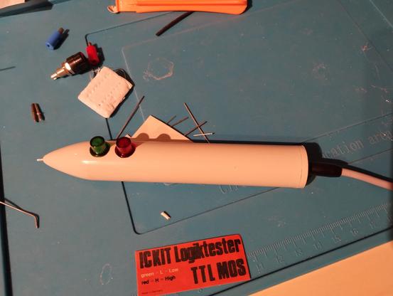
#LogicProbe
Jan Beta Makes A Simple 555 Based Logic Probe
#C64 #Commodore64 #555Timer #LogicProbe #ElectronicsDIY #CircuitBuilding #Instructables #ElectronicsTutorial #ILC555 #NE555 #DIYProjects #TestEquipment
https://theoasisbbs.com/jan-beta-makes-a-simple-555-based-logic-probe/?feed_id=1024&_unique_id=677bea5ce5c1e
Making a Simple 555 Based Logic Probe
https://makertube.net/videos/watch/5d1de72a-9686-4118-850d-1b1ef4f73863
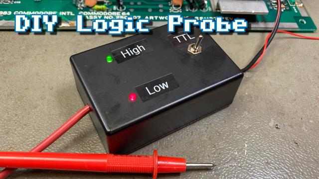
New video! I'm building a simple 555 timer based logic probe from spare parts I had laying around.
YouTube: https://youtu.be/NhgjBUmnA7k
PeerTube: https://makertube.net/w/cuUPCfYmzMeL8DkFuXgW2a
#LogicProbe #DIYLabEquipment #LogicTester #NE555 #555Timer #Circuit #Schematics #DIY #Homemade #Electronics #Tinkering
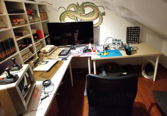
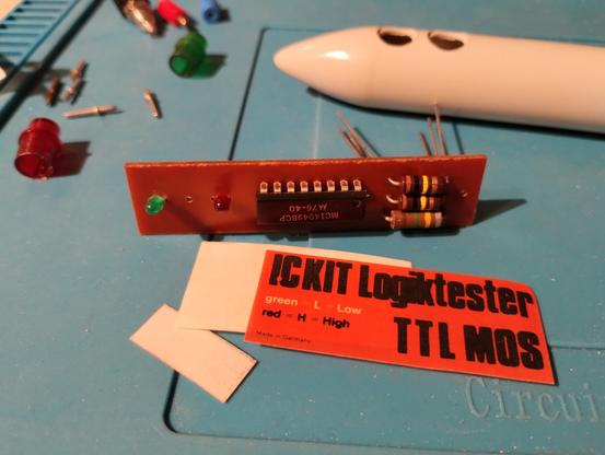
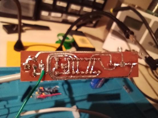
My new #soldering corner, almost finished setting it up. There will be another table right underneath the roof window on the right, where the final spot for the soldering station will be, so that the fumes get extracted better. But I had to give it a try, after so long no place for my hobby. A very old logic probe kit. I'll replace the LEDs with brighter ones, and the tip needs improvement. But I'm quite satisfied with my work and it was fun.
#electronics #hobby #solderingkit #logicprobe
