Raspberry Pi Pico BASIC: because nothing screams cutting-edge technology like resurrecting a programming language from the 1960s and slapping it on a microcontroller 🔄🤓. But wait, there's more—now you can enjoy the thrill of playing #Pong and building a "Precision Analog Clock" on a device that could probably power a small spaceship 🚀😂.
https://geoffg.net/picomite.html #RaspberryPiPico #BASIC #RetroTech #Microcontrollers #PrecisionAnalogClock #HackerNews #ngated
#RaspberryPiPico
Smarti, Schlepptopf - pöh laaaangweilich
Wer das Ding (wenn es denn einen Akku bekommt) im Zug ausm Rucksack hebt, Tastatur und Maus anschließt und loslegt ... 👀
Zitat:
Ein britischer Bastler hat den Macintosh aus dem Jahre 1984 im Miniformat nachgebaut. Er soll voll funktionsfähig sein
gerade einmal 62 Millimeter hoch
#Macintosh #RaspberryPiPico #RaspberryPi #Raspberry #PicoMac
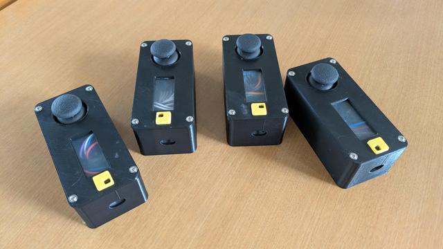
[#NSI 1re] Le projet "Manettes" entre dans sa phase III.
#raspberrypipico #pyxel #python
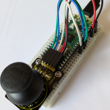
[#NSI 1re] Le projet "Manettes" entre dans sa phase II.
#raspberrypipico #pyxel #python
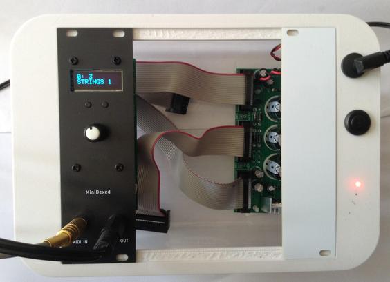
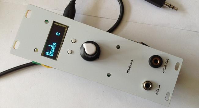
I finally have a good enough Eurorack version of my picoDexed.
https://diyelectromusic.com/2025/05/03/picodexed-minidexed-eurorack/
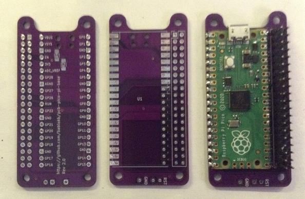
This is using a neat pico-to-zero adaptor from bablokb, released on Github, which allows me to use my existing MiniDexed PCBs and module with no other hardware changes.
picoDexed + MiniDexed EuroRack
Since attempting my picoDexed + StackyPi + MiniDexed EuroRack build and failing, I’ve found another Pico-to-Zero board that is provided as open source, so I’ve had some made.
This post details how to get that running with my MiniDexed Zero Eurorack module.
Warning! I strongly recommend using old or second hand equipment for your experiments. I am not responsible for any damage to expensive instruments!
If you are new to microcontrollers and single board computers, see the Getting Started pages.
Pi Zero RP2040s
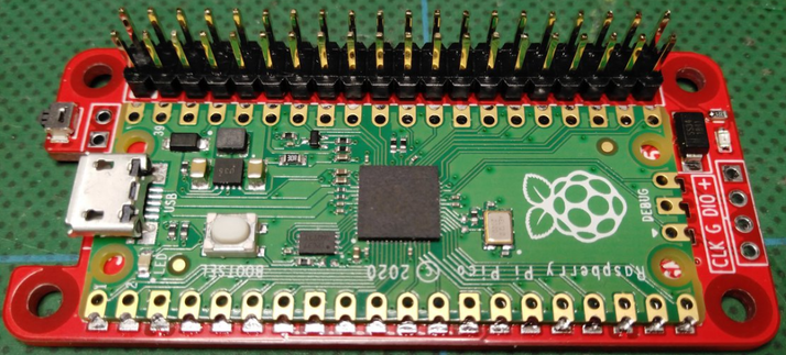
As mentioned last time I found a number of options for a RP2040 based dev board in a Raspberry Pi Zero form factor. But this post is about this one:
It is fairly simple to build. It just requires a Pico and GPIO header pins.
There is an option for pull-ups on the I2C bus, but I’ve not bothered with them here. There is also a breakout header for a reset switch if required (it will support two sizes of switch by the looks of things).
Mapping over to MiniDexed/RPi Zero
The pinout is slightly different to the Stacky-pi, so here is an updated table of the GPIO mappings and which are required to be used with my MiniDexed board.
RP2040UseRPiRpiUseRP20403V35VGP2LCD SDAGP2 SDA5VGP3LCD SCLGP3 SCLGNDGP4GP4GP14 TXDGP0GNDGP15 RXDMIDI INGP1GP5GP17GP18I2S BCLKGP18GP6GP27GNDGP7GP22GP23GP83V3GP24GP28GP11RE BGP10 MOSIGNDGP12RE AGP9 MISOGP25GP27GP10RE SWGP11 SCLKGP8GP9GNDGP7GP26ID_SDID_SCGP22SW BACKGP5GNDGP13SW HOMEGP6GP12GP21GP14GP13GNDGP19I2S LCLKGP19GP16GP20GP15GP26GP20GP17GNDGP21I2S DATAGP16The two key problem areas will be the I2S interface and encoder, which both require consecutive GPIO pins for the PIO code to do its magic.
The encoder should be fine – pins RE A and RE B map onto the Pico’s GP11 and 12.
The I2S interface might be ok – with a BCLK on GP18, it will be expecting LCLK on GP19. Data on GP21 should be ok.
Unlike the previous attempt, I’m hopeful I can just get this running ok with the correct pin mappings…
Changing I2C Bus and UARTs
Unlike the first attempt, I2C is mapped onto GP2 and GP3 which is what I was using in the original picoDexed. So that is all fine, multiplexed onto the I2C bus 1.
There is an issue with the UART however as picoDexed uses the following by default:
- UART 0 – GP 0,1 – Serial debug
- UART 1 – GP 4,5 – MIDI
I can swap these over so that UART0 (GP0,1) is MIDI, but that has to be matched with a change in the debug serial port too. But unfortunately, as far as I can see, that has to be configured in the master CMakeLists.txt file (as I talked about in Part 3).
New picoDexed GPIO Configuration
Given the above, the following new GPIO pins should be defined in config.h:
#define PWM_PIN         10

#define I2S_DATA_PIN    16
#define I2S_BCLK_PIN    18
#define I2S_LRCLK_PIN   19  // Implied by BCLK=12

#define MIDI_UART       0
#define MIDI_TX_PIN     0   // Not used
#define MIDI_RX_PIN     1

#define DEBUG_UART_TX_PIN  8
#define DEBUG_UART_RX_PIN  9

#define DISPLAY_I2C_BUS  1
#define DISPLAY_I2C_SDA  2
#define DISPLAY_I2C_SCL  3
#define DISPLAY_I2C_ADDR 0x3C
#define DISPLAY_W 128
#define DISPLAY_H 32

#define ENCODER_A_PIN  11
#define ENCODER_B_PIN  12 // Not used
#define ENCODER_SW_PIN 10 // Not used
In addition to this, to keep using the debug output requires the following lines adding to ‘target_compile_definitions’ in CMakeLists.txt.
    PICO_DEFAULT_UART=1
    PICO_DEFAULT_UART_TX_PIN=8
    PICO_DEFAULT_UART_RX_PIN=9
I’ve added a separate configuration file (config-ER.h) in the repository to allow this version to be built, but the CMakelists.txt change above has not been included.
I’ve also added a picodexed-v0.03-ER.uf2 file in the build area which can be downloaded and installed directly onto the Pico to provide the above configuration ready to go.
Bringing it all together…
The nice thing about this PCB is that I can map everything nicely over to the pinouts used with my MiniDexed EuroRack PCB meaning that once the Pico has the custom firmware installed, it will just plug in and work and no hardware changes or patching is required at all!
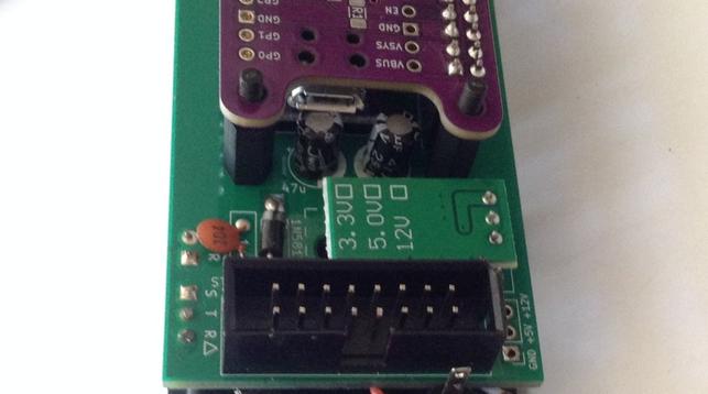
I was slightly concerned that the USB port of the Pico might clash with the two installed electrolytic capacitors on the MiniDexed PCB, but in my case I can just about get away with it!
Here is the final assembled unit.
Closing Thoughts
I finally have my Eurorack picoDexed which is pretty neat. Big thanks to bablokb for putting that PCB up online. That saved me a job. And it was particularly nice that things like assuming consecutive pins for the I2S mapping was included as that made using the PIO I2S code a lot easier.
I’d like to see what the power usage is like now as I’m really after a lower power Dexed engine compared to the full Zero version.
Naturally at some point I might still make my own picoDexed Eurorack PCB, but this is a pretty good solution as far as I’m concerned, so that wouldn’t really add much for me now.
Kevin
Raspberry Pi PicoでPicoMite(MMBasic)を使う〜OLEDディスプレイへの出力
https://qiita.com/ksakabe/items/48204558f388ad1daede?utm_campaign=popular_items&utm_medium=feed&utm_source=popular_items
#qiita #RaspberryPiPico #RaspberryPiPicoW #RaspberryPiPico2 #PicoMite #MMBasic
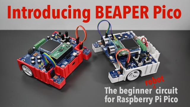
Wanna learn how to program a Raspberry Pi Pico? Wanna build a robot? Do both – and lots more – with BEAPER Pico!
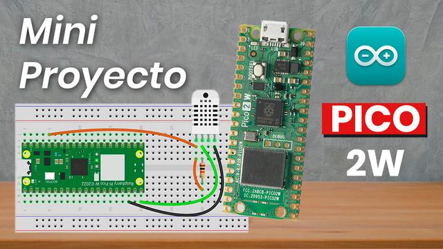
Raspberry Pi Pico 2 W + DHT22 Mini Proyecto Servidor Web
Aprovechamos la capacidad inalámbrica de la Raspberry Pi Pico 2 W para crear un servidor web que genera una página web y permite visualizar datos de temperatura y humedad de un sensor DHT22 mediante cualquier dispositivo con navegador web.
Un mini proyecto fácil de implementar con diagrama completo de conexión y código en IDE de Arduino explicado línea por línea.
Introducción a Raspberry Pi Pico 2W:
https://www.youtube.com/watch?v=cG89EN-pkWs
Código fuente del programa en:
https://github.com/bitwiseAr/Curso-Arduino-desde-cero/tree/master/RaspberryPiPico
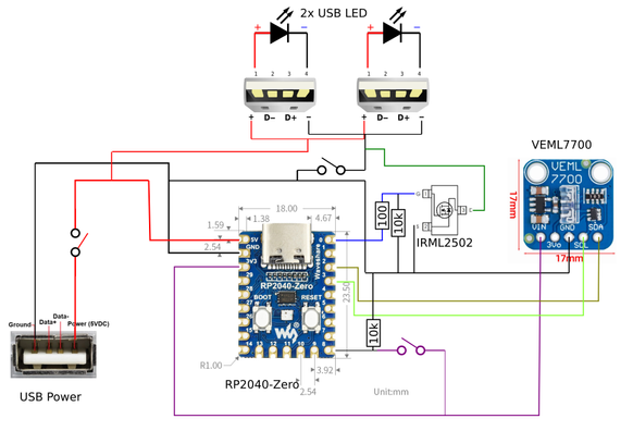
erster Entworf für ein offgrid licht mit Helligkeitserkennung(für den Hühnerstall) auf USB Basis (kann mit powerbank und USB Solarzelle betrieben werden), hat 3 Schalter (Dauerlicht, komplett aus und ein umschalter für die Leuchtdauer), es soll nach Sonnenuntergang 4/2 h leuchten damit die Tierchen nicht im dunkeln hocken #elektronik #schaltplan #circuit #usb #rp2040 #RaspberryPiPico #lichtsensor #led
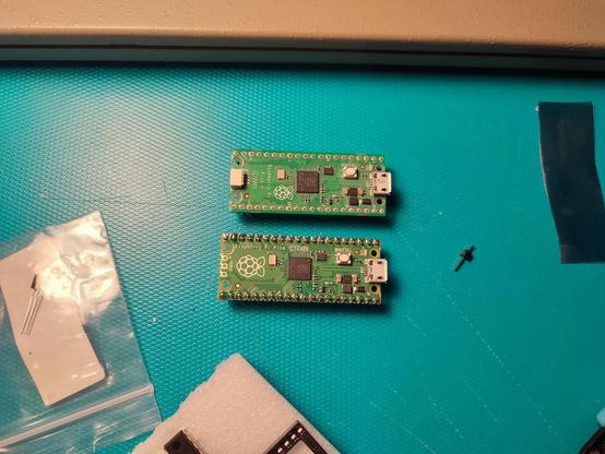
Having a spare Pico can always be handy, I still don't know how I killed it though: strangely it goes just fine in Bootsel mode, but starts rebooting as soon as I falsh MicroPython in it, while it will blink with a C demo... I guess that the storage got damaged?
https://silosneeded.com/2025/04/picoshock_devlog_2
#Playstation2 #Gaming #RaspberryPi #RaspberryPiPico
picoDexed + StackyPi + MiniDexed EuroRack
Now that I have a picoDexed with a display an encoder it is very tempting to create a version of my MiniDexed EuroRack PCB for it.
But as a short diversion, there is another possibility – can I use a RP2040 that is already in a Pi Zero form factor with my existing MiniDexed EuroRack PCB Design?
Spoilers: The answer, it turns out, is no. Something is not quite letting this work for me – it’s close, but I’m just not there yet. Here is another attempt where it works: picoDexed + MiniDexed EuroRack.
Warning! I strongly recommend using old or second hand equipment for your experiments. I am not responsible for any damage to expensive instruments!
If you are new to microcontrollers and single board computers, see the Getting Started pages.
Pi Zero RP2040s
I’m aware of a couple of products that were available to put a RP2040 into a Raspberry Pi Zero form factor:
- Red Robots Pico to Zero adaptor.
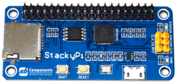
- Stacky-Pi by SB Components.
- Waveshare RP2040 PiZero.
- Pico to Pi HAT.
- Update: I’ve just found the following open source design: https://github.com/bablokb/pcb-pico-pi-base – details of how I’ve used this can be found here: picoDexed + MiniDexed EuroRack
The first two were available on Tindie and other places, and as far as I can see, both appear to use the same mapping of RP2040 GPIO to RPi 40-pin header. The Red Robot board doesn’t seem to be available anymore, and whilst there are a few Stacky-Pis on Tindie, in most places it seems to be discontinued.
I don’t know anything about the Waveshare or Pico to Pi, but might grab myself one of each.
I’ll give the open source design a try (and possibly save me designing my own…).
As can be seen above, the Red Robots board is designed to take an actual Pico, whereas the Stacky-Pi is its own board with an on-board RP2040.
Mapping over to MiniDexed/RPi Zero
The following table lists the RPi GPIO connections I used in my MiniDexed board and how they map onto the RP2040 using the above boards.
RP2040UseRPiRpiUseRP20403V35VGP20LCD SDAGP2 SDA5VGP21LCD SCLGP3 SCLGNDGP4GP14 TXDGP0GNDGP15 RXDMIDI INGP1GP17GP18I2S BCLKGP28GP27GNDGP22GP233V3GP24GP3RE BGP10 MOSIGNDGP4RE AGP9 MISOGP25GP2RE SWGP11 SCLKGP8GNDGP7ID_SDID_SCGP10SW BACKGP5GNDGP11SW HOMEGP6GP12GP12GP13GNDGP13I2S LCLKGP19GP16GP26GP20GNDGP21I2S DATAGP15The two key problem areas will be the I2S interface and encoder, which both require consecutive GPIO pins for the PIO code to do its magic.
The encoder should be fine – pins RE A and RE B map onto the Pico’s GP3 and 4.
The I2S interface is going to be tricky, as with a BCLK on GP28, it will be expecting LCLK on GP29 rather than the GP13 it is currently routed to on the board. Quite apart from the fact that GP29 isn’t even broken out on a Pico.
The obvious thing to explore is if the BCLK connection can be routed through to GP13 on the RPi header, or GP12 for the RP2040. That would be handy if so.
Connecting into GP13 should be possible as this pin is currently unconnected on the MiniDexed PCB. It will involve cutting a track however for GP18. The existing track and its new destination is highlighted below in blue.
Changing I2C Bus and UARTs
There is one other complication however. The picoDexed configuration has the ssd1306 connected to GP2 and GP3 which are multiplexed onto the I2C bus 1.
The adaptor configuration maps SDA/SCL onto GP20/21 which are multiplexed onto I2C bus 0. I updated the code to support changing I2C bus in addition to changing IO pins. Arguably, I should probably have supported this in the first place anyway…
A similar issue exists for the UART, but unfortunately that isn’t quite so easy to change.
I can take a similar approach to the above for the Serial MIDI link – allowing it to use either UART0 or UART1.
But that has to be matched with a change in the debug serial port too. But unfortunately, as far as I can see, that has to be configured in the master CMakeLists.txt file (as I talked about in Part 3).
New picoDexed GPIO Configuration
Given the above, the following new GPIO pins should be defined in config.h:
#define PWM_PIN         10

#define I2S_DATA_PIN    15
#define I2S_BCLK_PIN    12
#define I2S_LRCLK_PIN   13  // Implied by BCLK=12

#define MIDI_UART       0
#define MIDI_TX_PIN     0   // Not used
#define MIDI_RX_PIN     1

#define DEBUG_UART_TX_PIN  8
#define DEBUG_UART_RX_PIN  9

#define DISPLAY_I2C_BUS  0
#define DISPLAY_I2C_SDA  20
#define DISPLAY_I2C_SCL  21
#define DISPLAY_I2C_ADDR 0x3C
#define DISPLAY_W 128
#define DISPLAY_H 32

#define ENCODER_A_PIN  3
#define ENCODER_B_PIN  4 // Not used
#define ENCODER_SW_PIN 2 // Not used
In addition to this, to keep using the debug output requires the following lines adding to ‘target_compile_definitions’ in CMakeLists.txt.
    PICO_DEFAULT_UART=1
    PICO_DEFAULT_UART_TX_PIN=8
    PICO_DEFAULT_UART_RX_PIN=9
Bringing it all together…
I decided to hack on my (already pretty hacked) prototype MiniDexed EuroRack board and cut and patch the trace to the DAC as described above.
The complication being the GPIO header pin I need to get to is under the OLED display, but I could just about do it – see below.
It doesn’t work. Unfortunately.
First of, I have to say, I’ve not found the Stacky-Pi particularly reliable. It took me ages to get it to successfully boot up into accepting a uf2 file, and once installed, I was struggling to get it to reliably boot and run.
Weirdly it seems to work best when I have a finger on the flash chip which seems to imply some board layout/grounding/stability issues to me…
From what I can see, the display, MIDI, serial debug and encoder are working fine though once it does get up and running.
But I just can’t get any reliable sound out of the thing at all. I managed sound once, but that was it. It is all quiet unreliable for me – far too unreliable to be useful.
Shame, as it actually looks really cool!
Closing Thoughts
It has been a frustrating afternoon. I’m having to leave this one here for now as there are just too many unknowns at the moment to really get to the bottom of what is going on.
I thought the Stacky-Pi would be a quick and easy fix, but haven’t ever used them before, and the fact that they are discontinued and there is very little information that I can find online about them makes me think perhaps they aren’t worth persevering with.
So I have a number of options now:
- Try a Waveshare RP2040 PiZero. As there are a lot more peripherals, I’m not sure how much what I’m doing will translate across, to be honest, it cost wise, it’s essentially the same as a Zero itself, which I know “just works”.
- Do I design my own Pico to RPI GPIO converter board to let me use that with my existing MiniDexed EuroRack design? Tempting and probably not that hard.
- Update: I’ve since found (and ordered) https://github.com/bablokb/pcb-pico-pi-base
- Update 2: And it works! picoDexed + MiniDexed EuroRack
- Update: I’ve since found (and ordered) https://github.com/bablokb/pcb-pico-pi-base
- Do I attempt to do something with the Pico version of my EuroRack 6HP MCU Experimenter Module? Sounds initially easy but I suspect forcing a MiniDexed into this module eventually will hit other at the moment unforeseen issues.
- Or do I just go for it and put together a special picoDexed EuroRack module itself.
I might have one more go with the Stacky-Pi. I haven’t quite given up. I’ll have to do some research – maybe sprinkling a few capacitors around the board or some updated GND connections might help. Answers on a postcard (or in the comments) if you have any ideas.
I’ll get a Waveshare RP2040 PiZero on order, as I’ve had quite a bit of success with their own “Zero” miniature boards so far, and now I’d like it know if it would work 🙂
To be continued…
Kevin
#define #midi #minidexed #picodexed #raspberryPiPico #StackyPi
Raspberry Pi Pico Synth_Dexed – Revisited
I thought it was time I took another look at my Raspberry Pi Pico Synth_Dexed. I’ve a couple of main aims with coming back to this project:
- Update the build for the latest Pico SDK and Synth_Dexed.
- See what is involved in getting it running on an RP2350.
- See if a simple I2C display can be added and possibly an encoder or other controls.
- Actually document the architecture!
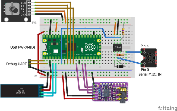
The current hardware is described in detail in Raspberry Pi Pico Synth_Dexed? – Part 5 and supports serial and USB MIDI, I2S or PWM audio output, voice selection (over MIDI) and up to 16 note polyphony if using an overclocked (to 250MHz) RP2040 based Pico and lower sample rate.
https://makertube.net/w/tY1u9qFz85NprRYPmtdvEj
Warning! I strongly recommend using old or second hand equipment for your experiments. I am not responsible for any damage to expensive instruments!
If you are new to microcontrollers, see the Getting Started pages.
Core Updates
Since I first put the PicoDexed together, V2 of the Raspberry Pi Pico SDK has been released. There aren’t many changes, but as noted by okyeron, an additional include file is required in main.c.
But as I was updating things, I also found a number of changes to Synth_Dexed too that broke the build. The most irritating of which was including a definition of DEXED_SAMPLE_RATE which now clashes with my own definition. I’ve gone through and changed a number of DEXED_ definitions to PICODEXED_ to avoid that in the future too.
A few other changes have also been introduced, which have necessitated an update to my diff file for Synth_Dexed/src/Dexed.cpp.
But on the whole, there was nothing major in the end. This has all been uploaded to GitHub as a v0.02.
PicoDexed Architecture
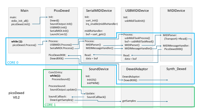
I had to go back and attempt to reacquaint myself with what I’d done last time, so as part of that I’ve drawn out a rough architecture diagram as shown below.
This expands on the design notes I’ve already written up in Part 3.
The key principles are as follows:
- Core 0 is used for all IO and is largely driven by MIDI events received over serial or USB.
- Core 1 is used for all audio processing and is run continually using the Pico’s audio driver (either I2S or PWM) to use a callback function to fill a buffer with samples to be played. The samples come from Synth_Dexed.
- All synthesis parameters (including keyup/down events for playing notes) is handled within picoDexed in response to the MIDIMessageHandler receiving MIDI messages from the MIDIParser.
Looking at this, I should be able to include some additional IO handling in the main Process loop of picoDexed that runs on core 0.
I2C Displays
Hunting around for libraries to support an SSD1306 display with the Pico SDK, so far I’ve found four options:
- pico-examples – has an example app that can put simple text or an image on an SSD1306. Note this isn’t created as a library that could be used however – it is all in a single example.
- sharkis/pico-ssd1306 – what appears to be a couple of files that can be included in your own code. It is pretty low-level with minimal options for any text or graphics and there is no documentation or licensing information as far as I can see.
- daschr/pico-ssd1306 – a higher level interface that provides basic graphics primitives and simple font support. MIT license. Again a couple of files to include in your project.
- Harbys/pico-ssd1306 – the most complete support I’ve found so far. What I’d consider to be a “proper” library with what seems to be good documentation and a wide range of usage options.
Whilst tempted to go with the “proper” library, it might be a little over the top for what I really need right now, and I don’t want to include an additional third-party GitHub link in my code at this time.
So I’m going to try daschr’s pico-ssd1306 as I can just grab the files, maintain the license information, and include it directly into my code.
To include this code in the build I’ve done the following:
- Created a libs area and copied in the files: ssd1306.c, ssd1306.h, font.h
- Added the c file to the CMakeLists.txt file.
- Added libs to the include path.
- Added hardware_i2c as an included library.
My new CMakeLists.txt file now looks as follows.
cmake_minimum_required(VERSION 3.13)
include(pico_sdk_import.cmake)
include(pico_extras_import.cmake)
project(picodexed)
pico_sdk_init()
add_executable(picodexed)

target_sources(picodexed PUBLIC
    ${CMAKE_CURRENT_LIST_DIR}/src/main.cpp
    ${CMAKE_CURRENT_LIST_DIR}/src/pico_perf.cpp
    ${CMAKE_CURRENT_LIST_DIR}/src/mididevice.cpp
    ${CMAKE_CURRENT_LIST_DIR}/src/picodexed.cpp
    ${CMAKE_CURRENT_LIST_DIR}/src/serialmidi.cpp
    ${CMAKE_CURRENT_LIST_DIR}/src/sounddevice.cpp
    ${CMAKE_CURRENT_LIST_DIR}/src/usbmidi.cpp
    ${CMAKE_CURRENT_LIST_DIR}/src/usbtask.c
    ${CMAKE_CURRENT_LIST_DIR}/src/usb_descriptors.c
    ${CMAKE_CURRENT_LIST_DIR}/libs/ssd1306.c
)

add_subdirectory(synth_dexed)

target_include_directories(picodexed PUBLIC
    ${CMAKE_CURRENT_LIST_DIR}/src
    ${CMAKE_CURRENT_LIST_DIR}/libs
    ${CMAKE_CURRENT_LIST_DIR}/synth_dexed/Synth_Dexed/src
    ${CMAKE_CURRENT_LIST_DIR}/synth_dexed
)

target_link_libraries(picodexed PUBLIC synth_dexed pico_stdlib pico_multicore tinyusb_device tinyusb_board pico_audio_i2s pico_audio_pwm hardware_i2c)

target_compile_definitions(picodexed PRIVATE
    PICO_AUDIO_I2S_MONO_OUTPUT=1
    PICO_AUDIO_I2S_MONO_INPUT=1
USE_AUDIO_I2S=1
    USE_AUDIO_PWM=1
)

pico_add_extra_outputs(picodexed)
The most basic usage is as follows:
static ssd1306_t disp;

i2c_init(i2c1, 400000);
gpio_set_function(2, GPIO_FUNC_I2C);
gpio_set_function(3, GPIO_FUNC_I2C);
gpio_pull_up(2);
gpio_pull_up(3);

disp.external_vcc=false;
ssd1306_init(&disp, 128, 32, 0x3c, i2c1);
ssd1306_clear(&disp);

ssd1306_draw_string(&disp, 8, 8, 2, "picoDexed");
ssd1306_show(&disp);
This initialises I2C bus 1 on GPIO 2 and 3 for device at address 0x3C.
Rotary Encoder
Taking the same approach with a rotary encoder, I’ve so far found the following as candidates for use:
- matteomeneghetti/pico-quadrature-encoder – provides a C++ API and uses PIO on two consecutive GPIO pins.
- jamon/pi-pico-pio-quadrature-encoder – simpler, and slightly lower level, PIO implementation only.
- GitJer/Some_RPI-Pico_stuff – example code of how to drive an encoder, again using PIO.
- pimoroni/pimoroni-pico/tree/encoder-pio/drivers/encoder-pio – Pimoroni driver for encoders using PIO.
The first is a more complete library, the second more “bare bones”. The last seems more of an example rather than a reusable object.
I was initially inclined towards the second which seemed likely to be easier to integrate into my own code, but as it was pretty low level and required a fair bit of glue around it.
Eventually I actually opted for something based on “GitJer”‘s example. There is a full explanation of how the code works here: https://github.com/GitJer/Some_RPI-Pico_stuff/tree/main/Rotary_encoder
I’ve had to change how voices are selected slightly to ensure the display, MIDI BANKSEL/PC and encoder can stay reasonably intuitive.
I’ve used the following logic:
- IF BANKSEL/PC both received then treat as Bank=0-7; Voice=0-31.
- IF PC on its own, then treat as Voice=0-127 across Banks 0 to 3.
- IF UI changes voices, then treat as Bank=0-7; Voice=0-31.
In each case the display shows the current bank and voice number in 0-7/0-31 format.
So just to be clear, MIDI Program Select on its own now (so 0..128) will always only select from the first four banks of 32 voices each. This is a change from the previous version which would allow PC to select based on the currently selected banks and the three following banks.
The encoder will automatically switch from one bank to the next, and wrap around at either end, so is able to select all voices across all installed banks.
Raspberry Pi Pico PIO Use
One issue to keep an eye on is PIO state-machine use.
I’m still getting my head around PIO (I’ve just not really devoted any significant time to figuring it out yet) but as I understand things, each PIO instance has a 32 instruction memory which is shared across four state machines.
So if there are several programmes to run and they all combined fit in the 32 instruction memory, then they could all use the same PIO instance whilst being attached to different state machines.
But if there are two vastly different programs to be running then it may be that they have to be split across the two PIO instances. But there can still be up to four instance of each program, one for each state machine in a PIO instance.
The I2S audio driver uses PIO to implement I2S. As far as I can see which PIO to use is determined by the following definitions:
PICO_AUDIO_PIO
PICO_AUDIO_I2S_PIO
PICO_AUDIO_PWM_PIO
If PICO_AUDIO_PIO is not defined then I2S_PIO and PWM_PIO are set to 0, which is then turned into “pio0” via the following in i2s_audio.c:
#define audio_pio __CONCAT(pio, PICO_AUDIO_I2S_PIO)
Which later on then uses the following to claim a free statemachine as part of audio_i2s_setup():
pio_sm_claim(audio_pio, sm);
I don’t know for certain, but it appears to me that the I2S PIO program is quite complete and so highly likely to fill the 32 word instruction memory.
On that basis, then the rotary encoder PIO program will have to use PIO instance 1 for its own code.
Summary of PIO use:
UsePIO InstanceNumber of State machinesI2SPIO 01EncoderPIO 11Update GPIO Usage
Expanding now on the table from Part 5, updated with the above, now gives the following GPIO usage map.
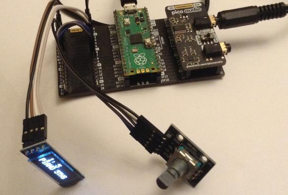
GP0Debug UART TXGP1Debug UART RX (unused at present)GP2SDA (I2C bus 1) OLED displayGP3SCL (I2C bus 1) OLED displayGP4MIDI TX (unused at present)GP5MIDI RXGP6Rotary Encoder AGP7Rotary Encoder BGP8Rotary Encoder Switch (not used)GP9I2S Data (DATA, DIN)GP10I2S Bit Clock (BCK)GP11I2S “Left/Right” Clock (LCK, LRCK, LR_CLOCK)GP20Optional: PWM outputGP22Optional: Mute pin for the Pimoroni Audio Pack (not used)VSYS5V power to DAC and OLED display (if required)3V3_OUT3V3 power to MIDI IN and encoder (if required)GNDPicoDexed on a Breadboard
Closing Thoughts
I feel like this is really starting to get interesting now. I have a few choices to make now – do I attempt to go for a more complete menu system similar to MiniDexed, or do I stay with MIDI control and basic voice selection as it is now?
Future enhancements might include:
- It will be interesting to see what supporting the RP2350 could bring.
- It would be useful to be able to set the MIDI channel – either in menu, or perhaps more ideally in hardware somehow (e.g. switches, resistors on an ADC, etc).
- Act as a USB host for USB MIDI devices.
In the video I’ve hooked it up to a serial MIDI controller and am just cycling through some of the voices showing how the UI works.
Kevin
#dac #dx7 #i2c #midi #picodexed #raspberryPiPico #rotaryEncoder #synthDexed
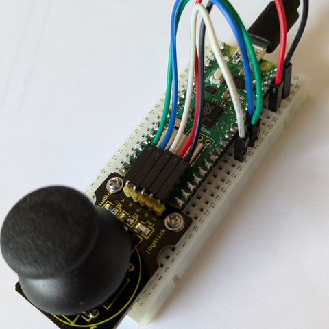
🕹️ La manette fonctionne!
#NSI #RaspberryPiPico
In other news, a copy of Jan Axelson’s “USB Complete” 5th edition arrived today. Hoping it can help me make sense of USB Audio 2, so I can make progress on my #RaspberryPiPico project! #PacketRadio #Embedded #HamRadio
RC2040
I’ve recently gotten hold of a RC2014 computer and it’s great. Once I’ve gone beyond some of the basic tutorials online I might start posting something about it at some point, so watch this space.
But also, I stumbled across the RC2040 project and kit from Extreme Kits (https://extkits.co.uk/product/rc2040/). Described as a “Retro emulated Z80 CP/M computer kit” it is basically a rc2014 emulated on a Raspberry Pi Pico. So I just had to get one to have a play with that too!
It comes as a PCB, acrylic baseplate and then a pile of components – mostly resistors, buttons, jumper. The PCB itself has the surface mount footprint for the Raspberry Pi Pico – and as it is essentially emulating a RC2014, hence the name RC2040.
These are my “notes to self” to remind me what I did to get up and running as the instructions are somewhat spread around and I felt assume a bit of knowledge of the RC2014 and the Z80 ecosystem that I don’t yet have.
Main resources and references:
- Product page: https://extkits.co.uk/product/rc2040/
- Project page: https://www.extremeelectronics.co.uk/the-rc2040/
- Getting started page: https://www.extremeelectronics.co.uk/the-rc2040-get-you-started/
- GitHub repository: https://github.com/ExtremeElectronics/RC2040
- Schematic: https://github.com/ExtremeElectronics/RC2040/blob/main/Circuit%20dagram/rc2040V2.pdf
- SD Card Contents: https://github.com/ExtremeElectronics/RC2040/tree/main/SD%20Card%20Contents
- Latest Firmware Release: https://github.com/ExtremeElectronics/RC2040/releases
- Relevant RC2014 Resources:
- Additional resources:
- rc2040.ini settings: https://www.extremeelectronics.co.uk/more-rc2040-settings/
- Pico GPIO settings: https://github.com/ExtremeElectronics/RC2040/blob/main/GPIO%20settings.md
- Serial CPM tools: https://github.com/ExtremeElectronics/RC2040/blob/main/SerialCPMtools.md
This post has the main usage points, which are mostly in the getting started pages, but with a few extras I had to figure out on the way too.
PCB Build Notes
If you’re thinking about getting one of these kits, take particularly note of the warning about the micro SD card connector.
This has to be soldered on using surface mount 1mm pitch connectors and to say it is fiddly is putting it mildly! And you almost certainly won’t know if you’ve succeeded until everything else is together and you’re reading data from the card…
There is a note on the product page to ask for help prior to ordering if you want it done for you.
I just went slowly with it, fixing one of the larger grounding pads first and then using that to orient the other pins before soldering any of the others. Then it was checked thoroughly with a magnifying glass before continuing.
Other things to consider:
- I went with the suggestion of using a slider switch for the USB/UART selector rather than jumper headers. This is connected to GP13 and used by the firmware to decide where to direct the serial output – over USB or to the UART. The outer position means UART, and the position nearer the Pico means USB.
- There is a speaker socket, which links to GP14, GP15 and GND directly with no additional circuitry.
- There is a FTDI socket which is connected to GP0, GP1, 5V (VBUS) and GND. There is a solder jumper (JP2) on the underside of the board that is unconnected by default, that determines if 5V comes from FDTI or not.
- There is also a solder jumper (JP1) to select 3V3 or 5V serial on the FTDI header. This is connected by default for 5V operation as it connects a 22K resistor from the header “TX” pin to GND, making a resistor divider with the 10K in series resistor. Note: TX on the header goes to the Pico RX Pin (GP1), and RX goes to TX (GP0).
- Although it isn’t shown on the schematic (that I could spot) there is also a solder jumper (JP3) on the underside of the board “has switches”. This is connected by default and indicates that there are configuration switches on this board (see later).
- It wasn’t immediately obvious (to me) which way round the LED went, but probing with a meter, the cathode is the pin nearest the edge of the board which connects via the 1K resistor to GND.
With hindsight, I suspect it would have been more useful for me to have had switches instead of the A13, A14, A15 jumpers and a jumper for the USB/UART setting.
Boot Configurations
This is one area I was getting quite confused over… I think there is where knowledge of the RC2014 boot options and ROM sets would really help, but what I think is happening is as follows.
The ROM file provided is 24886009.bin. Each number represents a single bank of the ROM and consequently an address jumper setting. Following the key from here, this decodes as:
- Bank 0 – 000 – 2 – Microsoft BASIC, for 32k RAM, SIO/2, with origin 0x0000
- Bank 1 – 001 – 4 – Microsoft BASIC, for 56k RAM, SIO/2, with origin 0x0000
- Bank 2+3 – 010 – 88 – Small Computer Monitor for pageable ROM, 64k RAM, SIO/2 or 68B50 ACIA, with Microsoft BASIC and CP/M boot options
- Bank 4 – 100 – 6 – CP/M Monitor, for pageable ROM, 64k RAM, SIO/2, CF Module at 0x10, with origin at 0x0000
- Bank 5 – 101 – 0 – Empty
- Bank 6 – 110 – 0 – Empty
- Bank 7 – 111 – 9 – Small Computer Monitor for any ROM, any RAM, any UART
When the RC2040 is oriented with USB on the left and the address jumpers at the bottom right of the board, the order is inverted. For the A13-A14-A15 Jumper settings: “1” is the position nearest the Pico; “0” is the position nearest the edge of the board.
So, in A13-A14-A15 order the options are:
- 000 – Bank 0: Boot into MS Basic
- 001 – Bank 4: Z80 SBC Boot ROM
- 010 – Bank 2+3: SC monitor
The following go into a loop for me:
- 100 – Bank 1: Repeated “>” in a loop
- 111 – Bank 7: Repeated “Read Fail” then drops into SC monitor
As might be expected the remaining two options (101,011) do nothing.
MS Basic (000) is the same as the standard image for RC2014 that I had by default with my kit.
Booting into the SC monitor (010) works fine too. When selecting help (“?”) there are three options at the bottom to boot into BASIC, WBASIC (“warm start” BASIC) or CPM.
Booting into the CP/M monitor appears to offer some basic options (once the “press [space] to access console” message appears and space has been pressed), but apparently only the boot into CP/M will work.
It would seem that the most versatile option is to use the SC monitor (010) mode for now.
A side note on boot configuration
There are a number of places in the emulator code where a choice is made between reading configuration switches and using a configuration from the rc2040.ini file on the SD Card.
There is a hardware indication of using switches. This is determined by the setting of GP22. In the board, this is tied to GND which means “this board has switches” (i.e. address jumpers). But it is tied to GND via a (connected) solder jumper which doesn’t appear to be on the schematic. This also determines if the USB/UART jumper is present.
There is also a config setting which can determined if the switches should be overridden by what is in the config file. This is the setting [ROM]\ovjump. If this is present and set to 1 then the A13-A14-A15 values are read from the rc2040.ini file rather than the A13-A14-A15 jumper settings.
In the readme file for the SD card contents, two rc2040.ini configurations are described. The actual rc2040.ini file present is the SIO2 configuration.
Usage Notes
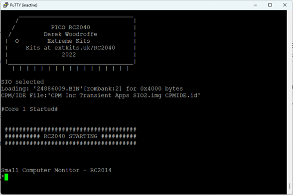
When using USB serial, the board will pause until a serial link is established. This is pretty handy as when resetting the Pico I lose the connection in PuTTY, but on “Restart Session” the session is re-established and the Pico will then boot up.
The buttons do the following:
- Pico RESET. This is hard-wired to the Pico RUN pin so does a proper hardware reset of the Pico.
- Z80 RESET. This is on GP7 and performs a “soft” reset, in that it performs an emulator Z80 reset.
- BUT. On GP8. This is related to fast file transfers apparently (tbd).
- DUMP. GP9. Dumps the RAM contents to the serial terminal and SD card.
There is a good reference for additional useful rc2040.ini file settings here: https://www.extremeelectronics.co.uk/more-rc2040-settings/
GP16,17,18,19,20,21,26,27 are broken out on an additional header and form the 8 bits of a single Z80 IO port. By default this is at PORT address 0 but that can be changed with the [PORT]\pioa rc2040.ini file option.
Conclusion
This will do for the time being. I think I now understand how this can boot into either BASIC or CP/M, so next is to do some reading about how to get different programmes running under CP/M.
Kevin
Probíhá radost 😊
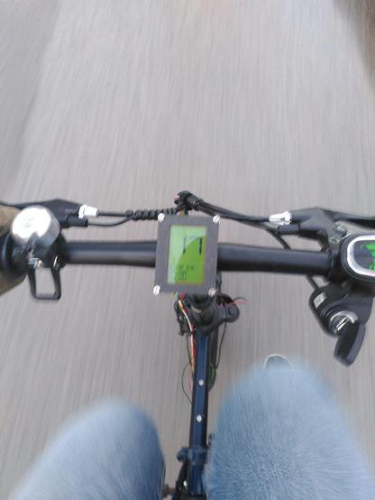
Ještě dodělat ty světla a blinkry, kvůli kterým jsem to vlastně původně celý začal 😂
