@michaelborthwick frustrations yesterday when I seemed to corrupt the one booting disk image which had the rf2025 document on it. Bah.
Binary Dinosaurs
Collecting and repairing home computers since 1998. Also at facebook.com/binarydinosaurs and binarydinosaurs.co.uk.
Favourite COBOL code: MOVE CORRESPONDING BEARS TO PORRIDGE.
@karttu ah yes, you’re right.
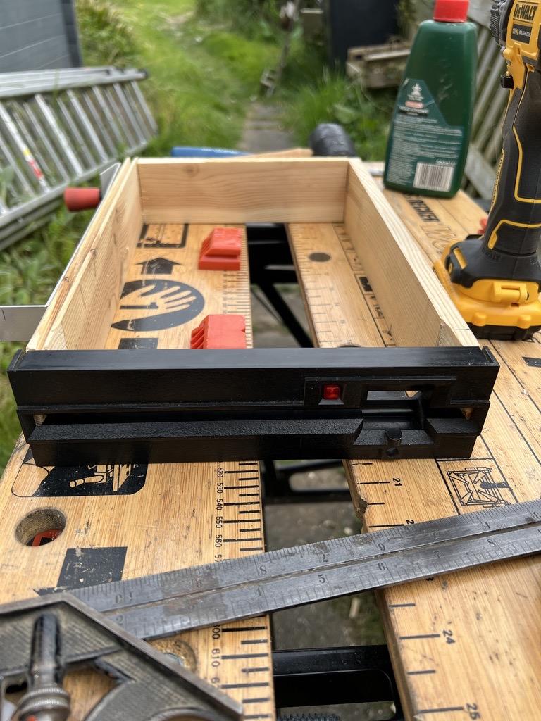
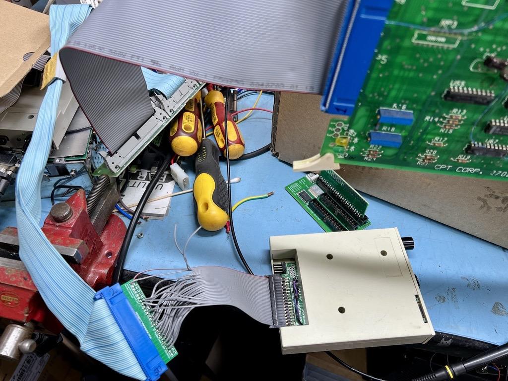
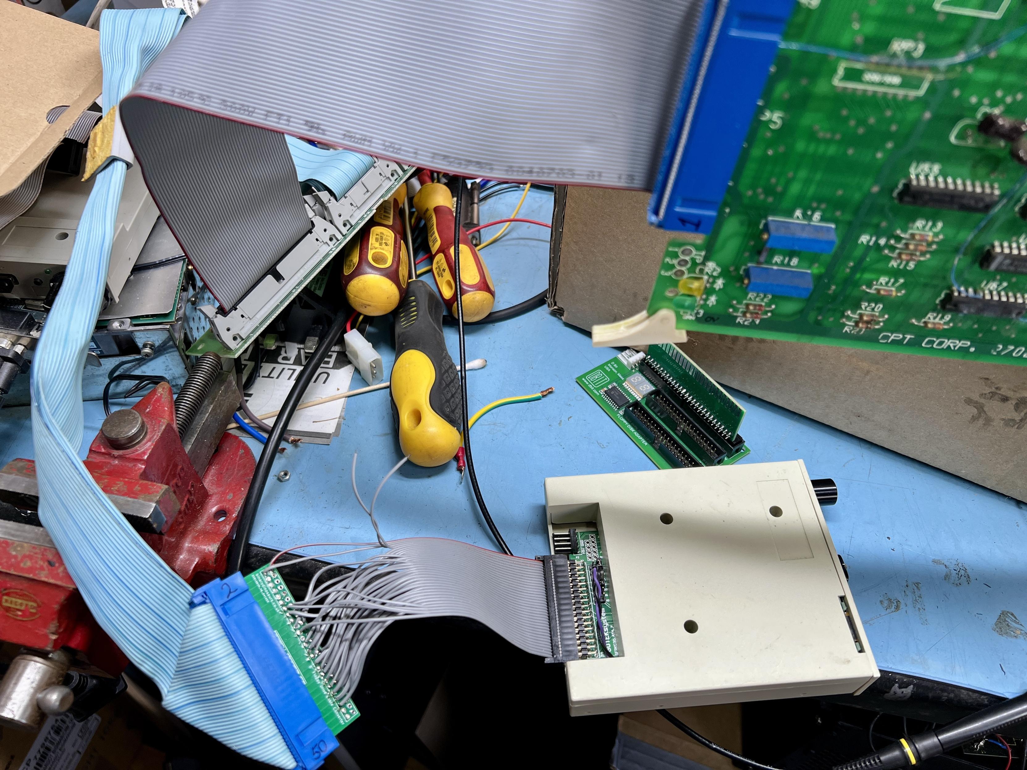
RetroFest preparations continued yesterday. I made a fake floppy drive to hide the Gotek in, now I just need to invent a way of selecting images. I know HOW I want to do it, it's just a question of if I CAN without having a 3D printer or CAD skills...
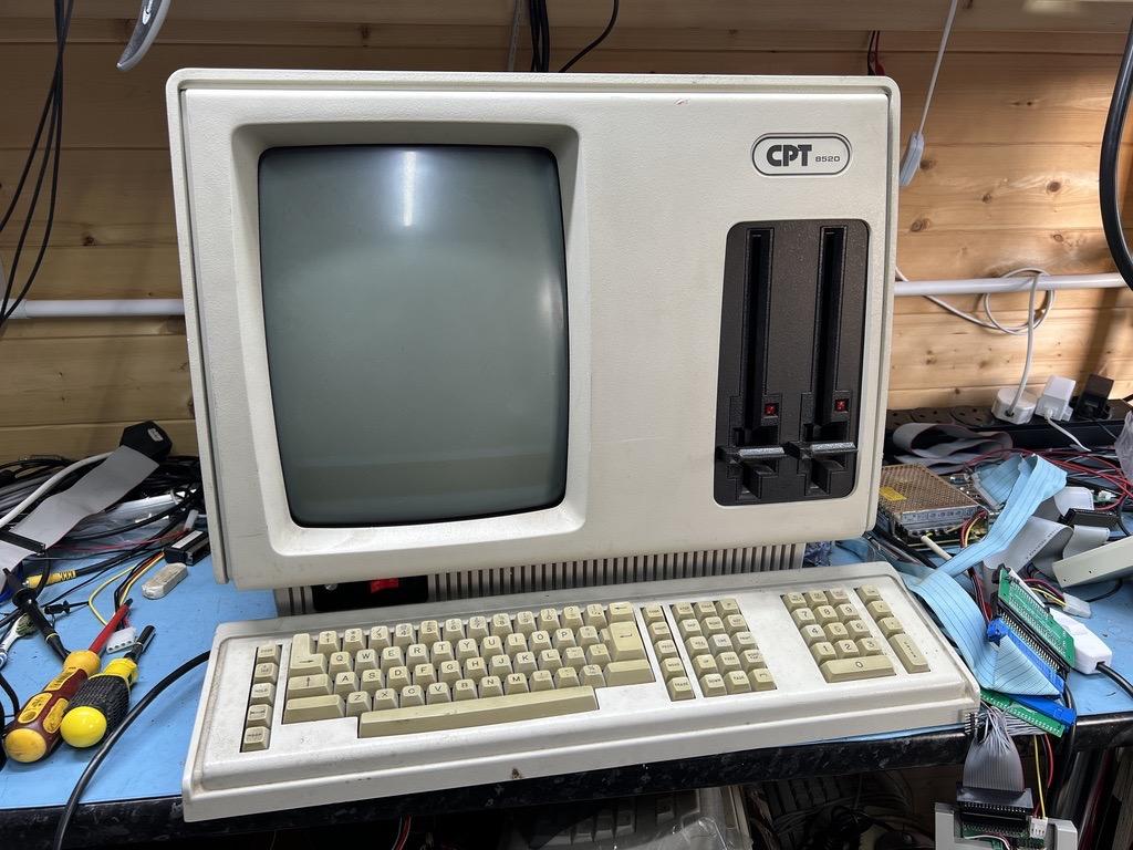
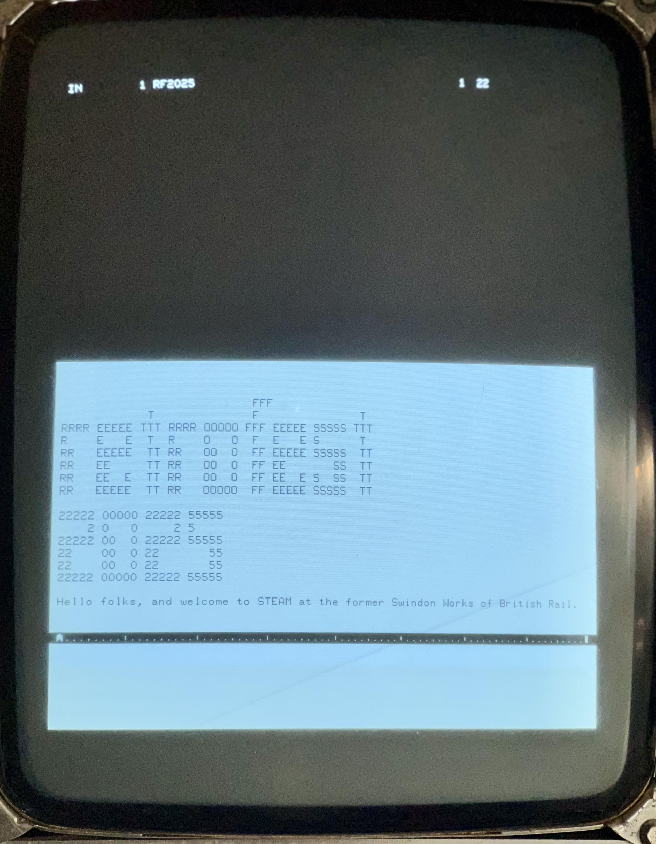
Finally, RetroFest 2025 is coming up on May 31st/June 1st at STEAM in the old Swindon British Rail works. This beast will be there along with some technology that came out the year after this machine - the Apple Lisa.
See you there!
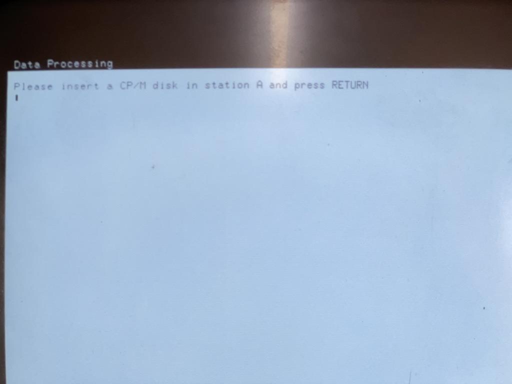
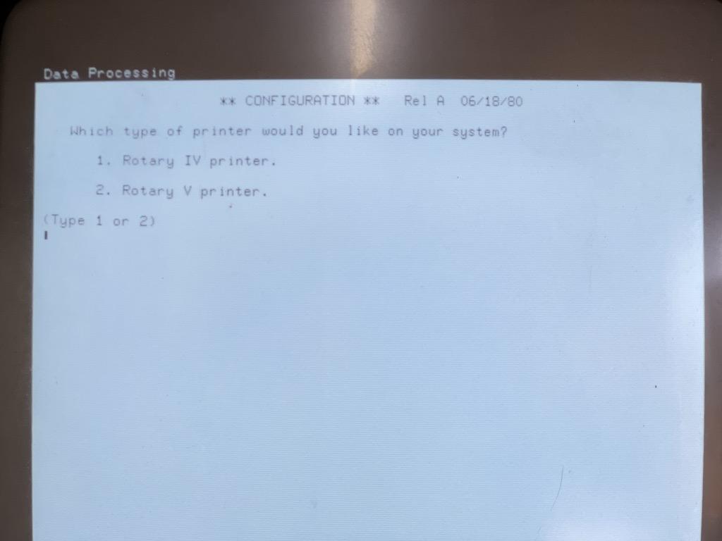
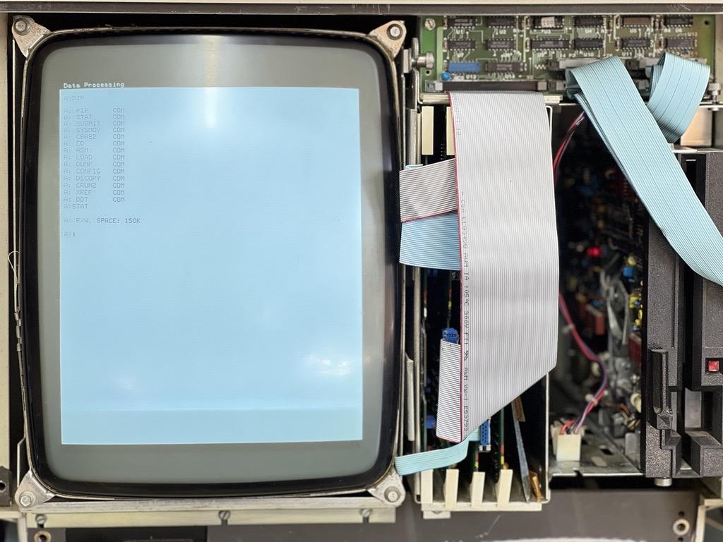
Next - CP/M. I knew CP/M existed for the CPT series, and also that CPT themselves used it internally. However, I couldn't get it to boot and suspected bad images. Then I read the CompuPak docs that came with my image bundle.
Because CP/M isn't native to the 8080 in the machine you need to load a 'software interface' disk first, I'm guessing this is a CPU emulator. THEN you boot CP/M and thankfully I had both images and...
They both work :D
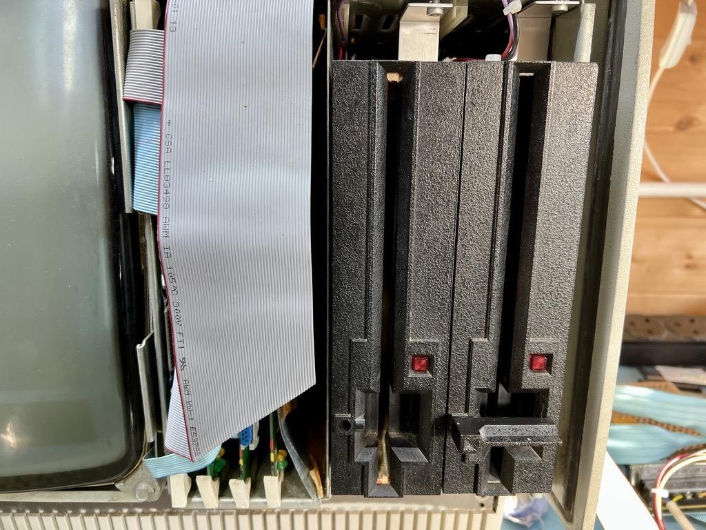
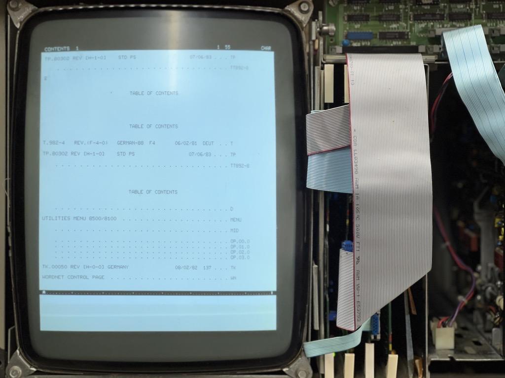
Moar CPT! Manual tells me it works like a typewriter and treats the reader as a typist. It explains the features and, more importantly, how to get to the various functions and how the floppy drives work.
The drives are called STATION ONE and STATION TWO. You store and recall docs using OUT and IN keys. To get a disk list you use CODE-IN to get a Table Of Contents. Neat.
There are 4 OPERATIONS - 2 word processing, disk copy and disk erase. CODE-O gets those. I can't get them to work though.

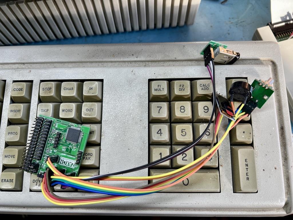
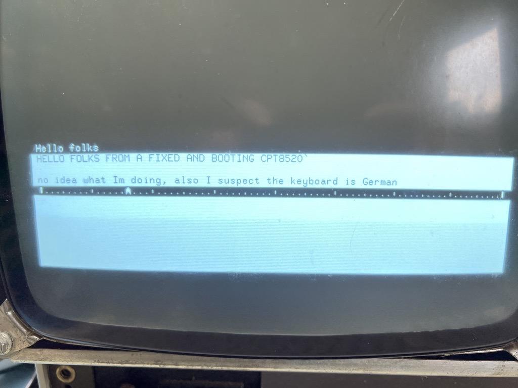
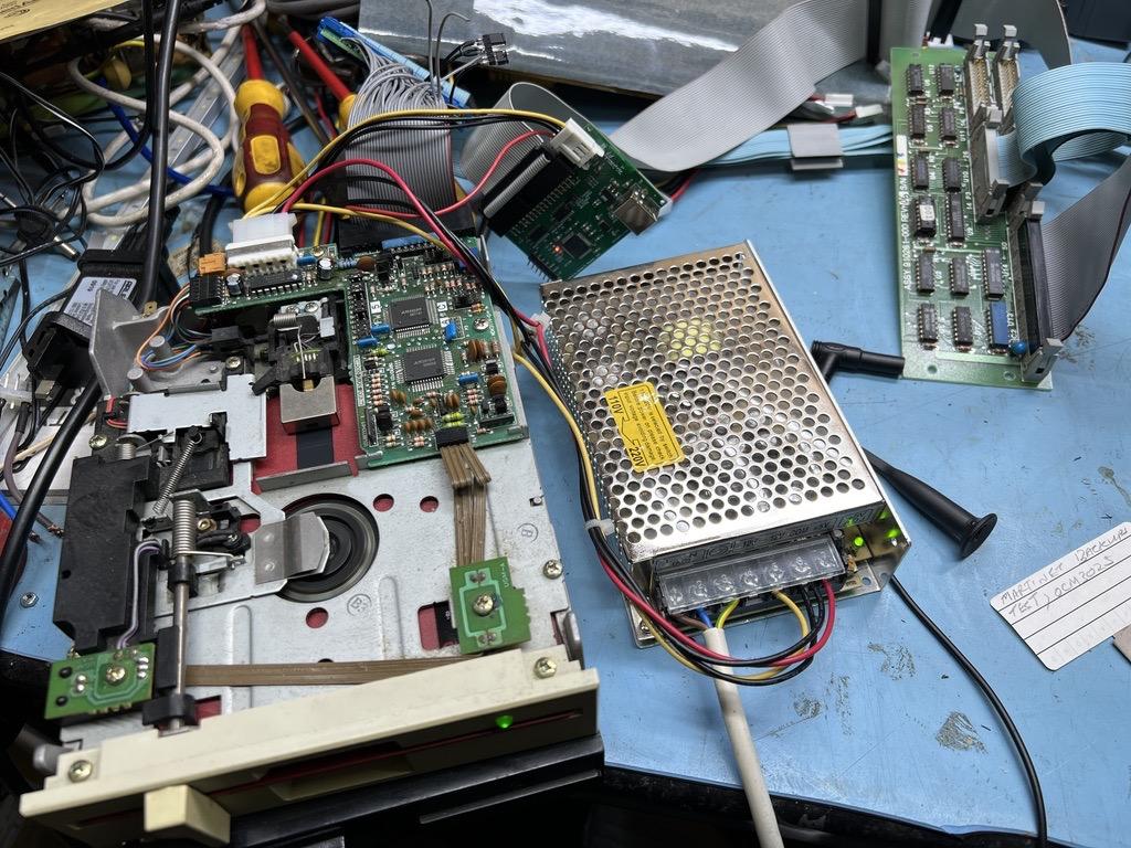
More CPT! What if it's not the data coming off the Gotek, but something in the path between it and CPU not working? The RAM board has a LOT of 4116 chips on it, and we know what they're like. I remembered I had a spare board set so swapped in a 64KB board.
It booted! I saw the word processing screen for the first time 🥳 Hooked up the keyboard and I could type! My only working image is German however, so AZERTY keys, but IT WORKS.
Time to read the user manual.

More CPT8520 updates. I remembered a former CPT staffer explaining the boot process to me, and why the red 'parity' light on the CPU board would come on. Basically the data coming from the 'floppy' was bad, but the Gotek made the right moves.
Hooked up a real drive and watched that with a scratch disk in. It did the same - seeking the head in and out several times. Then I remembered that 1.2MB 5.25" drives can sometimes replace 8" so I did that too. Same result.
It's trying!
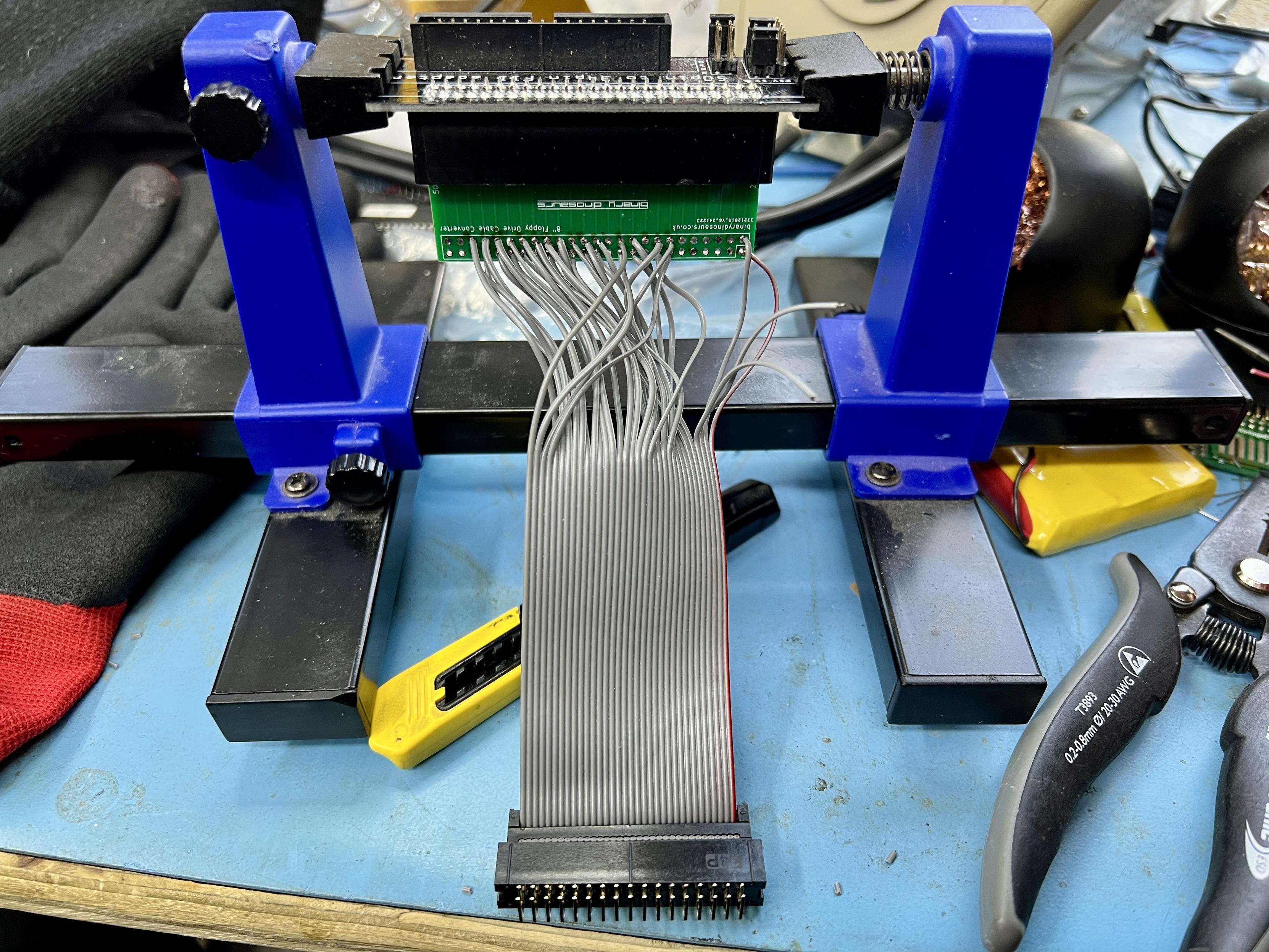
This morning it occurred to me that the DBIT FDADAP 3.5"-8" floppy adapter might not be bidirectional. A post on the VCFED agreed with me, so back to the drawing board. Fortunately nf6x (Mark) on there had designed a simple adapter and had a schematic on his gitlab so I rewired one of my own adapters I designed at xmas.
It kind of works. The READY light pulses on the gotek so it's trying to boot, but it doesn't like my disk images. More testing needed.
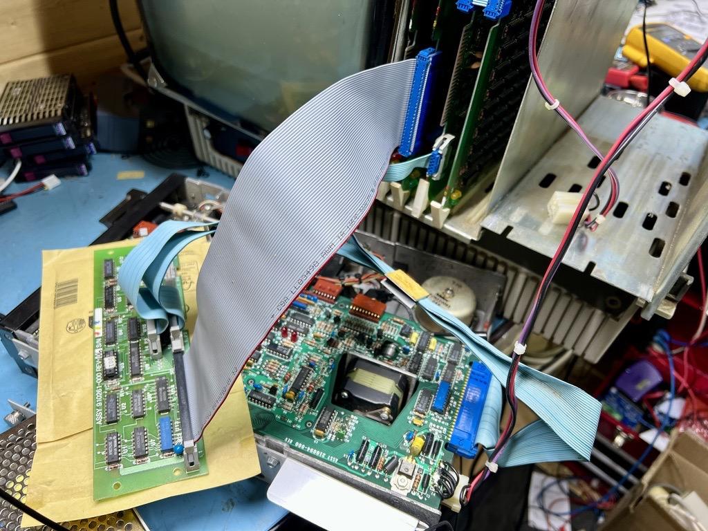
Success with the monster CPT8520 today. Well, 'success' in that after a TON of measuring, DMM buzzing and checking of Stuff I powered up with my over-xmas-designed riser board and it made all the right noises and prompted for a boot disk.
Added the floppy controller after replacing the burnt traces on the 5V rail and the world didn't end. All voltages present and correct, pin 3 (/CS) on the WD1771 formatter pulses at boot so it's waiting for a floppy :D
Tomorrow I add those parts...
@VintageProject Yep. I kept some good drives for media I've still got and might want to read, but it's getting to the point where I should just attempt to dump everything to a different media type now that there's so many options for even my VAXen and PDPs.
@VintageProject The full height ones are Quantum DLT40/80 and take DLT IV carts. the smaller one is indeed a 3.5" DAT. Threw a few of them out when we cleared the old warehouse last year, but I kept the brand new DLT40/80 and I don't know why 😆 Shiny I suppose.
Binary Dinosaurs boosted:
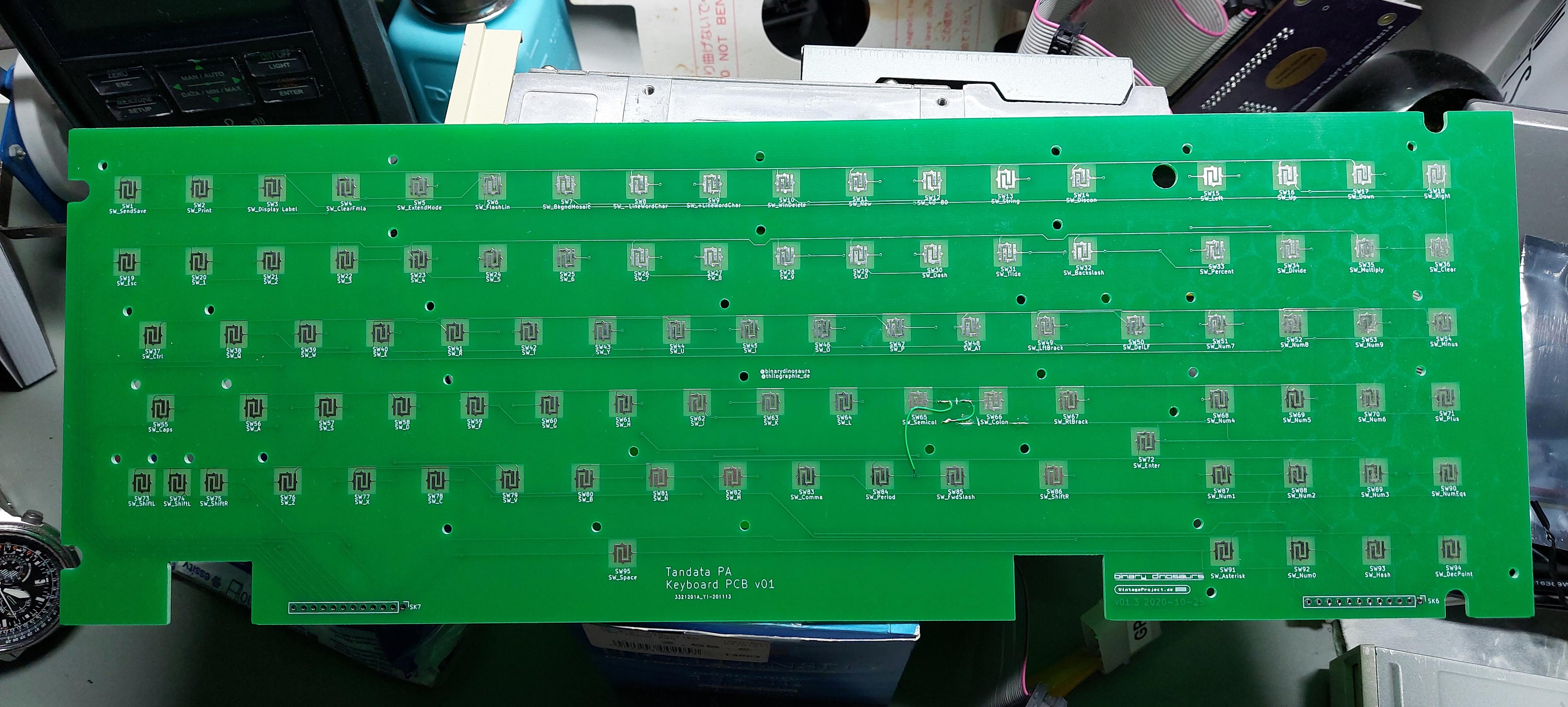
Look what arrived today:
A PCB from a very fruitful cooperation with @binarydinosaurs that I was granted around 2019/2020.
This is a reproduction of the keyboard PCB of a Tandata PA.
The original PCB was severely damaged by corrosion, and the decision was made to roll a new one to make the Tandata PA operational again.
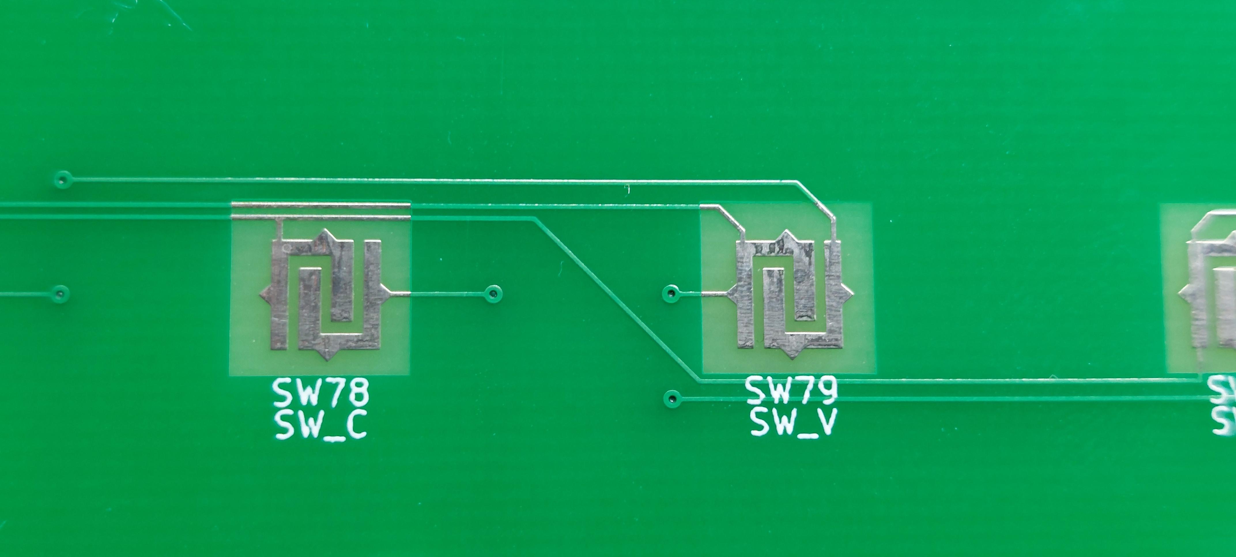
One of the hurdles was to recreate the unusual footprints for the key switches. That wasn't too bad in KiCad, though.
Awesome!
Thank you very much!
It's marvellous to see what has become of the humble beginnings back then. 😊
I think this needs to be framed and put on the wall. (Unless I come across another Tandata PA, that is. 😎)
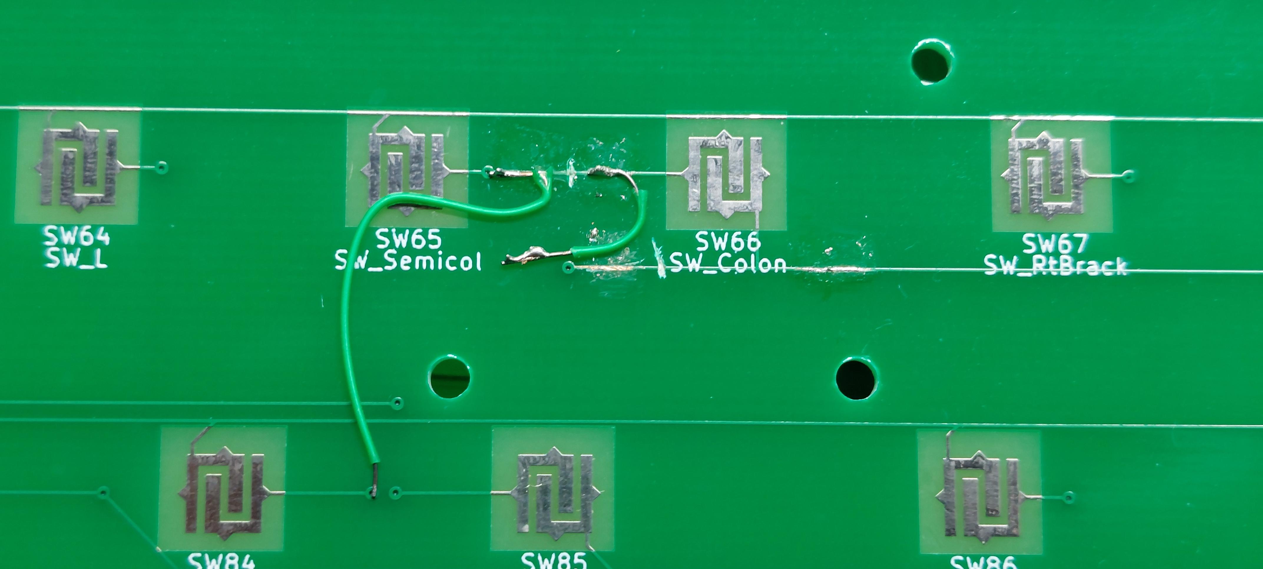
Unfortunately, either Royal Mail or whoever handled it here tore a few of the mod wires. I'll repair those soonish.
Find @binarydinosaur's report here:
https://binarydinosaurs.co.uk/Museum/Tandata/pa.php
@LaurentFr Nice! I wasn't aware of that one.
@anachrocomputer Yes, correct. I was just going to say 'you have beard!' then I realised I've not seen a pic of you for donkey's years :D
@VintageProject Hello! I still have this Tandata keyboard for you, it's been sat in a spare room for longer than I care to admit while I waited for our postal service to sort itself out.
It won't get any better, it will only get worse.
Send me your address again please, I'll get it posted before it becomes impossible to send to the EU :/
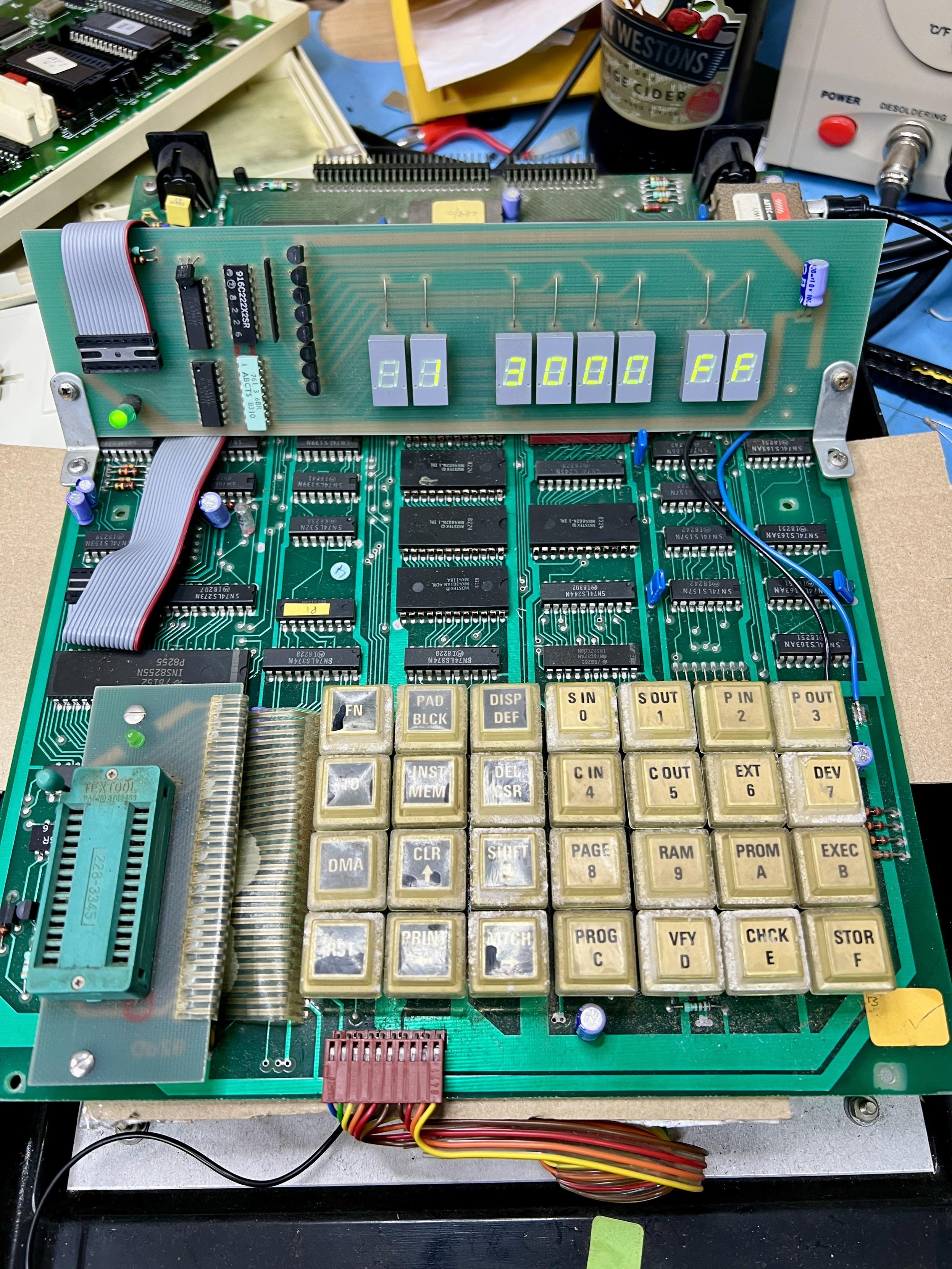
But will it work when reassembled?
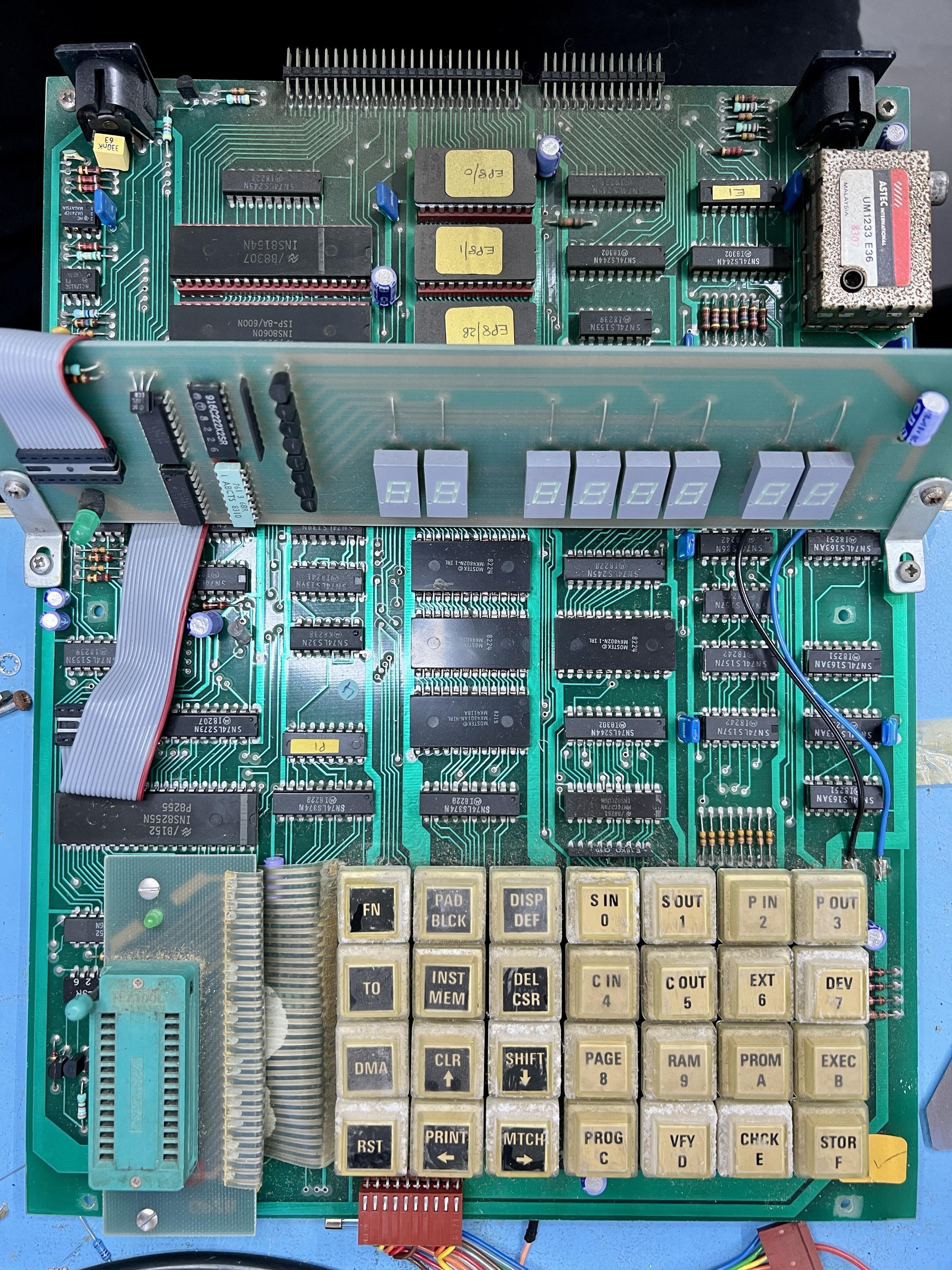
Yes, yes it will. Excellent. Given that this thing supports 3-rail EPROMs like the 2708 it'll be interesting to see if it will read my Nascom EPROMs. There's a serial port on the back so it should transmit to a PC running RealTerm, or unix box running minicom...
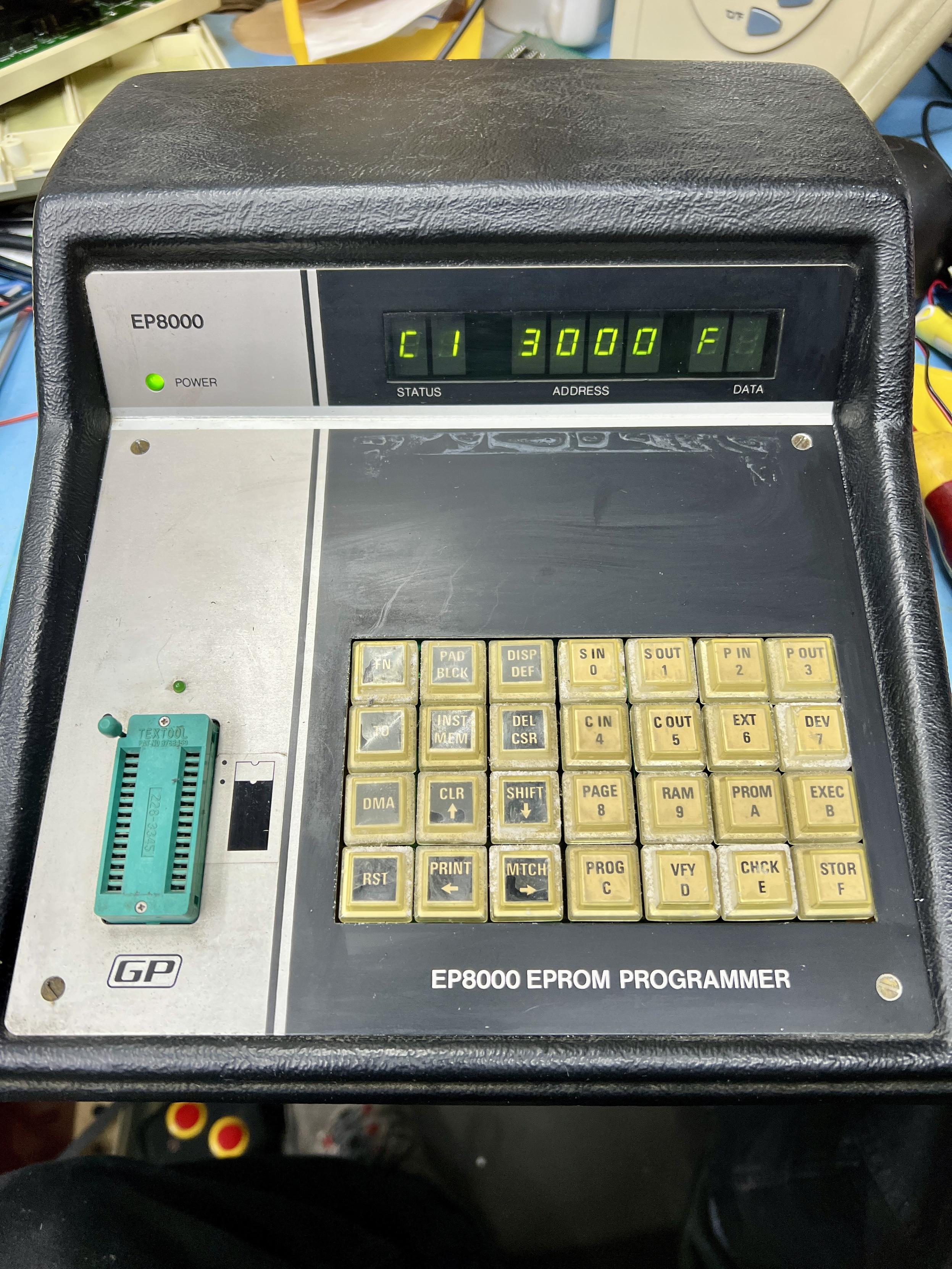
The only damage I could see was that the power LED had been crushed against the display board by miscreants unknown of the past - I'd never taken it to bits before today. Plug it in and... it works? That wasn't in the script.
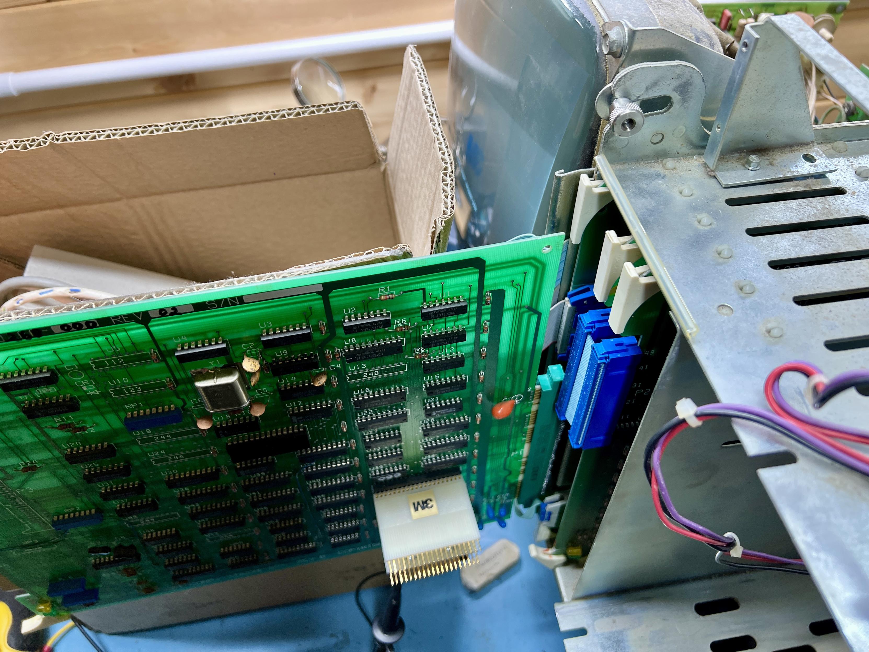
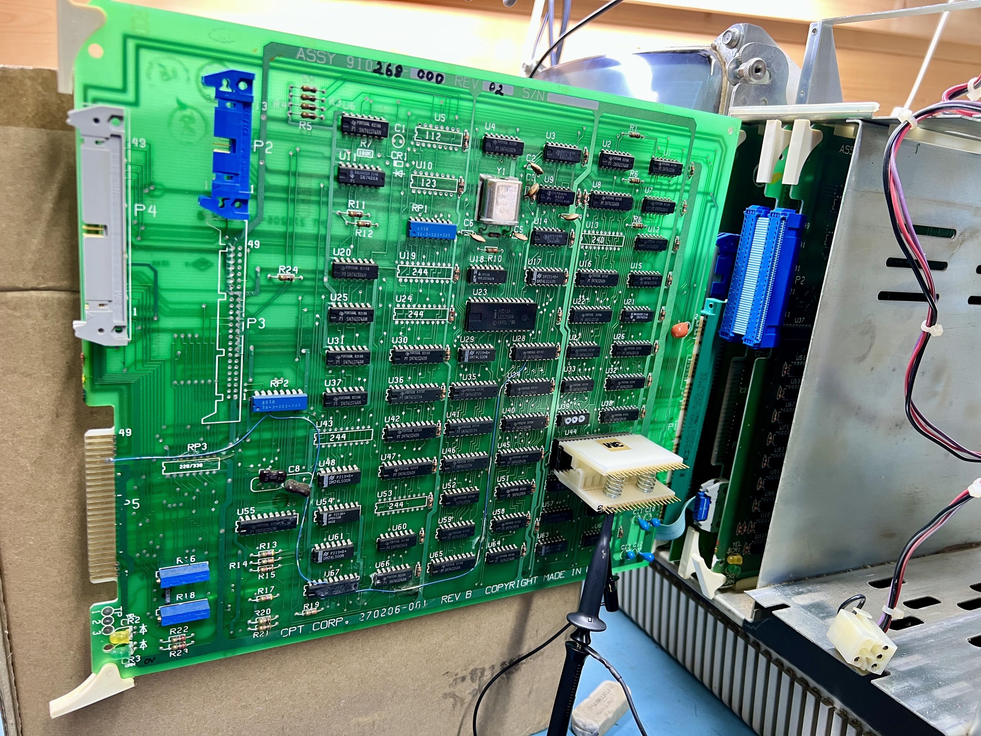
Yep, the 40 pin DIPs at top left are the IMS8060N SC/MP microprocessor and its 128kx8 RAM I/O chip. NatSemi's favourite little CPU family as used in some kit-based SBCs like the SCRUMPI and Science of Cambridge MK14.
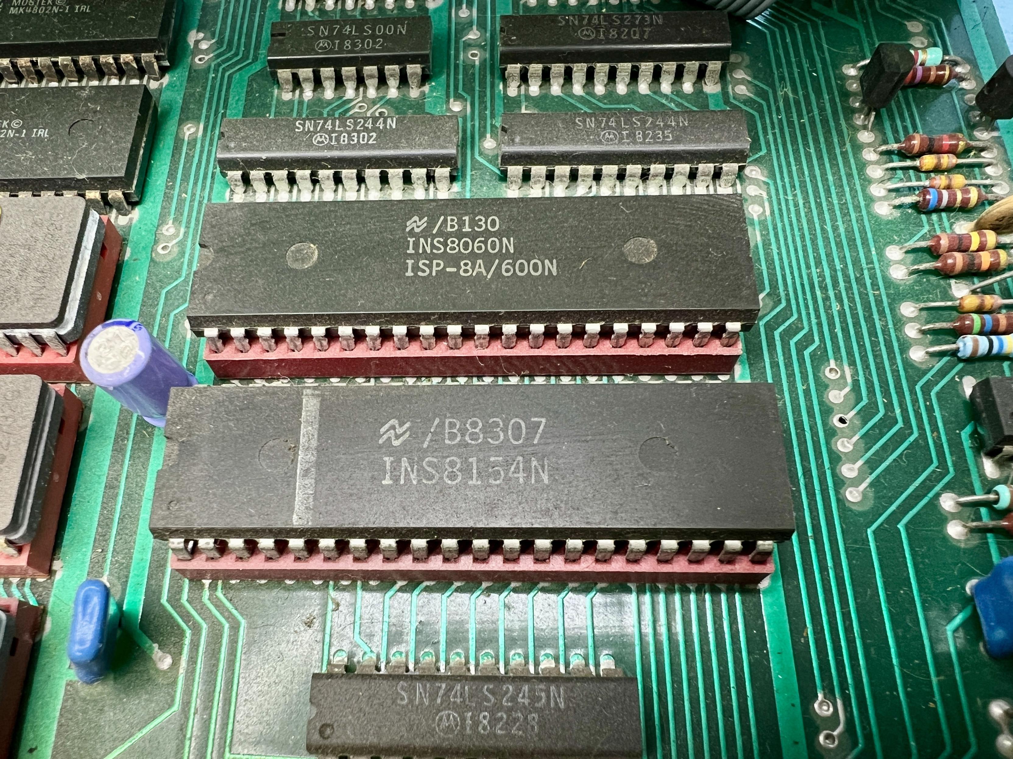
Easy to dismantle after unhooking the GND connection to the top metal plate and unplugging the PSU. Gaze in wonder at its green-ness, and also two suspicious-looking chips up at the top left.
Client Info
Server: https://mastodon.social
Version: 2025.04
Repository: https://github.com/cyevgeniy/lmst