#define NULL 0 /* silly thing is, we don't even use this */
-- Larry Wall in perl.c from the perl source code
#Define
¿Usar un debugger como gdb?
Naa, a mi dejame con los printf metidos por todos lados, y una directiva #define para activarlos o desactivarlos a todos juntos cuando la cosa se complica 😆

防御型空母
防御型空母。日本では空母保有を巡って、議論が、一応''なさられてる''一応。
https://note.com/poison_raika/n/nd8be14f2aa74
<>
#japan #reality #like #define #international #support #problem #attack #scope #distance #understand #aircraft #enemy #limit #introduce #various #carrier #proposal #rescue #counterattack #missions #restrictions #defensive #territorial

I like using stdbool.h.
My reasoning is that in #C , especially on unix, 0 is sometimes true.
So using stdbool.h for simple boolean stuff makes me not have to worry about that.
I can see one of the "Other" options is that for very localized code, you
will know what you mean for any give call that returns something boolean-like.
Like if I was programming something for a microcontroller, I can see
not using stdbool.h.
(But it is so small, I am guessing it's negligible after compilation.)
On #OpenBSD all it basically is is the #define(s) true = 1 and false = 0.
@david_chisnall you can use `typeof` for this too
#define Const(x) typeof(const typeof(x))
#define Volatile(x) typeof(volatile typeof(x))
Const(int *) pointer_that_is_const;
Const(int) * pointer_to_const;
@ljs @thesamesam @osandov @vbabka Or use a self-documenting macro, something like this?
#define __tagged_pointer(nr_bits) \
__attribute__((aligned(((1 << nr_bits) + 7) / 8)))
@gloriouscow my money is on timing. can you #define every printf into a usleep() or such?
Arduino with Multiple Displays – Part 3
Whilst messing around a little more with my Arduino with Multiple Displays – Part 2, I’ve optimised the code a little and found out a bit more about these displays!
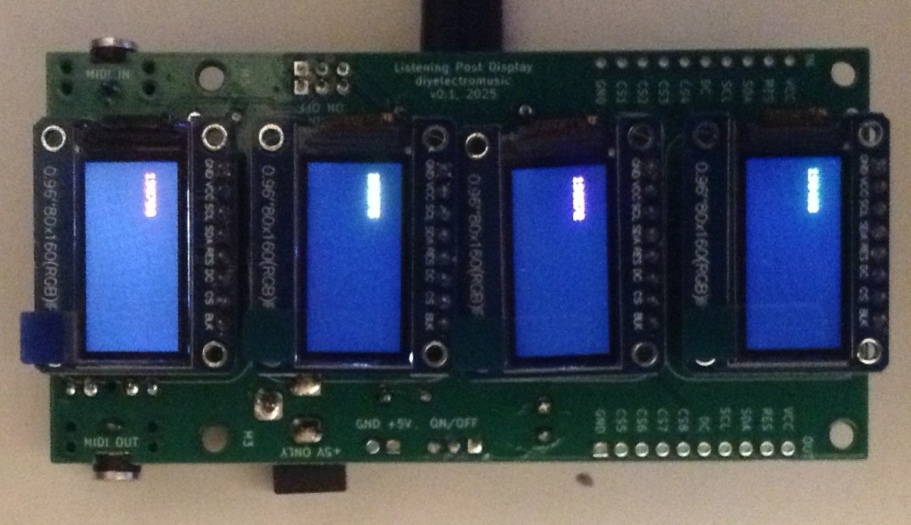
In this part, I’m actually using a PCB that can hold four displays, powered by a Waveshare Zero device. More on that here: Waveshare Zero Multi Display PCB Design.
Warning! I strongly recommend using old or second hand equipment for your experiments. I am not responsible for any damage to expensive instruments!
These are the key Arduino tutorials for the main concepts used in this project:
- Arduino with Multiple Displays
- https://emalliab.wordpress.com/2025/07/19/small-microcontroller-displays/
If you are new to microcontrollers, see the Getting Started pages.
Parts list
- A Waveshare Zero format board or similar
- 4x 0.96″ ST7735 60×180 SPI TFT displays.
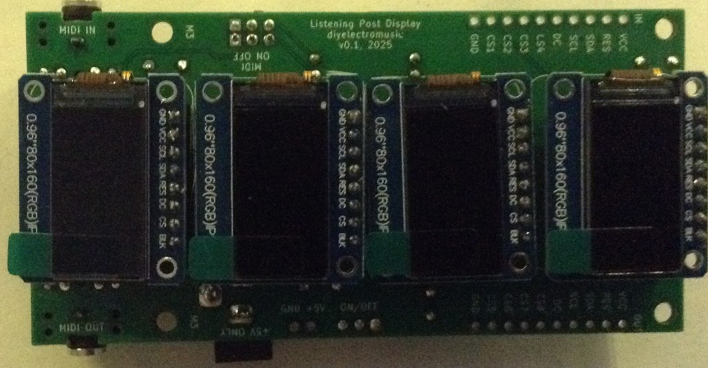
- Built Waveshare Zero Multi Display PCB
- Breadboard and jumper wires.
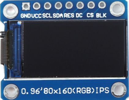
Recall that I’m using displays that look like this – note the order of the pins.
Although even with displays that look exactly the same, it appears there can be differences in how they are used software wise. More on that later.
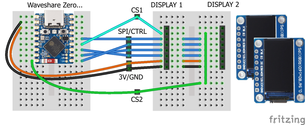
The Circuit
For two displays, I can reuse the circuit from Arduino with Multiple Displays – Part 2. For more displays, it is possible to cascade more displays using jumper wires, but I’ve used my PCB.
The pins to be used for various Waveshare Zero boards is covered in part 2.
The Code
Whilst using these displays, I found that the colours can be inverted in some of them compared to others. Typically, I’ve found that I might have to use either of the following two options to drive them correctly:
tft.initR(INITR_MINI160x80);
tft.initR(INITR_MINI160x80_PLUGIN);
These represent different Adafruit displays as before, but they generally work for me.
However there is another thing to watch out for. These displays are 16-bit colour displays, which means each colour value is a 16-bit word with red, green and blue elements represented by 5, 6 and 5 bits. This means two of the colours have a resolution of 0 to 31, and one has 0 to 63.
But the ordering seems different for different displays. The default Adafruit library appears to assume RGB ordering, but my displays seem to be BGR. This means that if I use the provided short-cuts for colours, the red and blue elements are swapped.
Consequently, I defined my own colours along with a macro to allow me to provide RGB values and turn it into the device-specific 16-bit value as required.
In the following, I define the bit-shift number for each of red, green and blue and the use that in a macro “ST_COL”. Red and blue are the 5-bit colours and green is the 6-bit colour.
// Format is 16-bit 5-6-5 B-G-R
#define RBV  0
#define GBV  5
#define BBV 11
#define ST_COL(r,g,b) (((r&0x1F)<<RBV)|((g&0x3F)<<GBV)|((b&0x1F)<<BBV))
#define ST_BLACK   ST_COL(0,0,0)
#define ST_WHITE   ST_COL(31,63,31)
#define ST_BLUE    ST_COL(0,0,31)
#define ST_GREEN   ST_COL(0,63,0)
#define ST_RED     ST_COL(31,0,0)
#define ST_YELLOW  ST_COL(31,63,0)
#define ST_MAGENTA ST_COL(31,0,31)
#define ST_CYAN    ST_COL(0,63,31)
I’m also building up to seeing if I can drive more than four displays, so I’ve also changed the code to allow me to iterate across a number of displays.
#define NUM_TFTS 4
int tftTypes[NUM_TFTS] = {
 INITR_MINI160x80, INITR_MINI160x80,
 INITR_MINI160x80, INITR_MINI160x80,
};

int tftCS[NUM_TFTS] = {SPI_SS, 6, 5, 4};
#define TFT_RST     7
#define TFT_DC     11

Adafruit_ST7735 *tft[NUM_TFTS];

void setup() {
  int rstPin = TFT_RST;0
  for (int i=0; i<NUM_TFTS; i++) {
    tft[i] = new Adafruit_ST7735(&MySPI, tftCS[i], TFT_DC, rstPin);
    rstPin = -1;
    tft[i]->initR(tftTypes[i]);
    tft[i]->setRotation(3);
    tft[i]->fillScreen(ST_BLACK);
  }
}

void loop() {
  for (int i=0; i<NUM_TFTS; i++) {
    unsigned long time = millis();
    tft[i]->fillRect(10, 20, tft[i]->width(), 20, ST_BLACK);
    tft[i]->setTextColor(ST_GREEN);
    tft[i]->setCursor(10, 20);
    tft[i]->print(i);
    tft[i]->print(":");
    tft[i]->print(time, DEC);
  }
}
Each instance of the display code is now created dynamically and stored in an array which can then be iterated over when it comes to putting things on each display.
Notice how the reset pin definition is set to -1 after the first initialisation. This ensures that subsequent instantiations won’t reset displays that have already been set up.
The final code actually allows up to eight displays to be included by setting NUM_TFTS at the top to two or four.
The GPIO usage being assumed is described here: Waveshare Zero Multi Display PCB Build Guide.
Closing Thoughts
Approaching the code in this way allows me to experiment more easily with more than four displays.
If my PCB works as I’m hoping I should be able to cascade them to get eight displays – assuming the Waveshare Zero is up to driving eight of course.
Kevin
#arduinoUno #define #esp32c3 #ESP32s3 #rp2040 #st7735 #tftDisplay #WaveshareZero
@beccadax @siracusa Ah, it's easy to tell -- signals! That's where both UNIX and C end... in tears.
(Separately, for the OP, this is why you should always have a header somewhere that #define's TRUE 0 and FALSE 1, just in case! Not that you'd want to use it everywhere, of course, that'd just be silly)
sys/arch/aarch64/aarch64: locore.S
skrll: Remove unnecessary line continuations in printcpu (it's not a #define)
http://cvsweb.netbsd.org/bsdweb.cgi/src/sys/arch/aarch64/aarch64/locore.S.diff?r1=1.98&r2=1.99
The ca65 documentation warns against using .define unless you really have to.
Plz don't tell ca65 all of the horrible things I did with #define in gcc....
Aha, ich war mal kurn in den Quellcode abgetaucht.
./app/tools/gimplevelstool.c Zeile 458 setzt die Höhe dieser Dreiecke auf CONTROL_HEIGHT, was ein #define mit Wert 10 ist, also nur compile-time-konfigurierbar, nicht nachträglich.
./app/widgets/gimphandlebar.c ab Zeile 176 werden die drei Dreiecke mittels `cairo_(move|line)_to` gemalt.
Jetzt erstmal bisschen Wald, später dann einen Patch schreiben und neu kompilieren.
gimp 2.10.38-r2, Gentoo, falls es bei Euch in anderen Zeilen ist.
wondering why this didn't become a popular convention:
// in a generated "config.h":
#define foo(header) </path/to/library-foo/include/header>
// in any non-generated file:
#include foo(bar/a.h)
- the preprocessor sees an absolute path, which means it doesn't consult the '-I' options for this `# include`.
- this means the programmer doesn't need to think about header search behavior (including shadowing).
- since the compiler doesn't do a header search, it may have helped build times.
防御型空母て何? What is a defensive aircraft carrier?
防御型空母。日本では空母保有を巡って、議論が、一応''なさられてる''一応。
Defensive aircraft carrier. In Japan, there is some discussion about having an aircraft carrier.
https://www.pixiv.net/novel/show.php?id=20023587
#japan #reality #like #define #international #support #problem #attack #scope #distance #understand #aircraft #enemy #limit #introduce #various #carrier #proposal #rescue #counterattack #missions #restrictions #defensive #territorial
10 Years of Cyberfunk with Xtrah (UK), Simple Technique, Vittjas Tief, DE.fine, Aynaet, Upzet @ Void Club - 30 Aug feat. Xtrah, Vittjas Tief, DE.fine + more

Client Info
Server: https://mastodon.social
Version: 2025.07
Repository: https://github.com/cyevgeniy/lmst