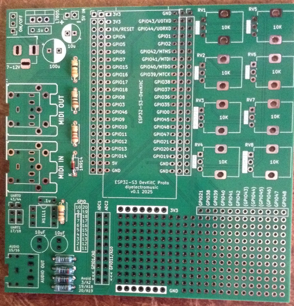
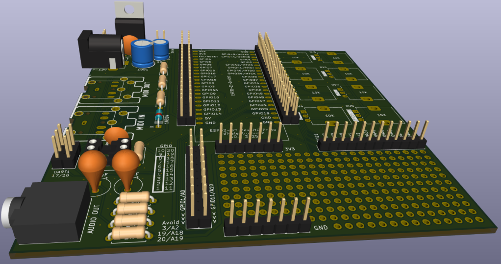
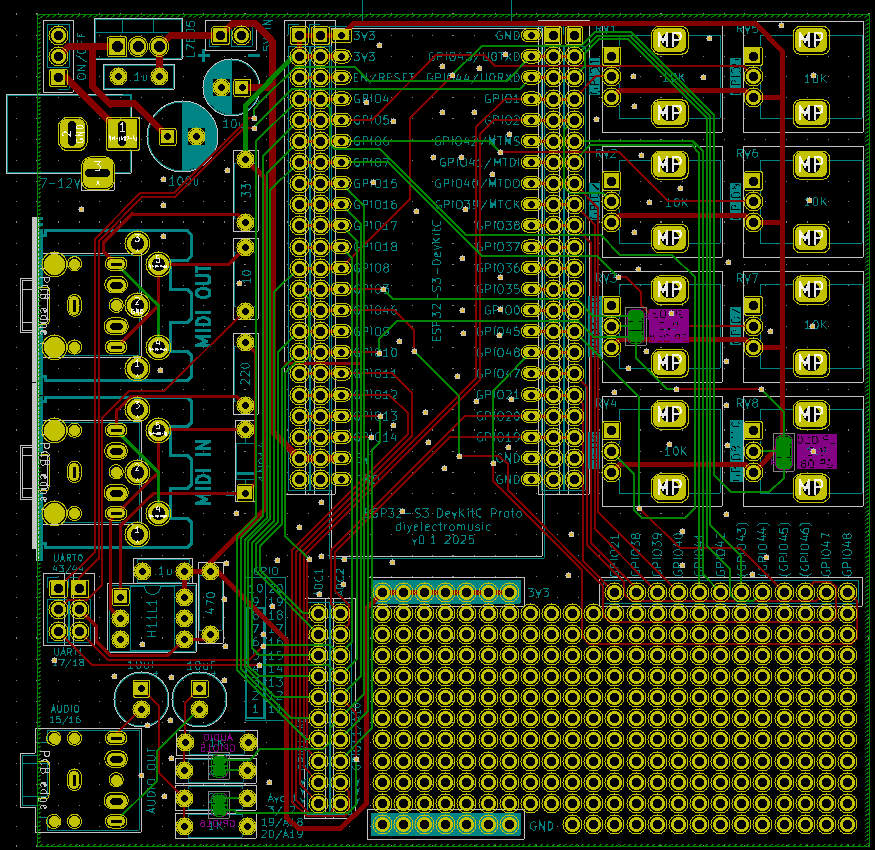
An ESP32-S3 DevKitC prototyping board with MIDI, PWM audio output, potentiometers and its own power circuit.
https://diyelectromusic.com/2025/05/25/esp32-s3-devkit-experimenter-pcb-design/
An ESP32-S3 DevKitC prototyping board with MIDI, PWM audio output, potentiometers and its own power circuit.
https://diyelectromusic.com/2025/05/25/esp32-s3-devkit-experimenter-pcb-design/
ESP32 S3 DevKit Experimenter PCB Build Guide
Here are the build notes for my ESP32 S3 DevKit Experimenter PCB Design.
Warning! I strongly recommend using old or second hand equipment for your experiments. I am not responsible for any damage to expensive instruments!
If you are new to electronics and microcontrollers, see the Getting Started pages.
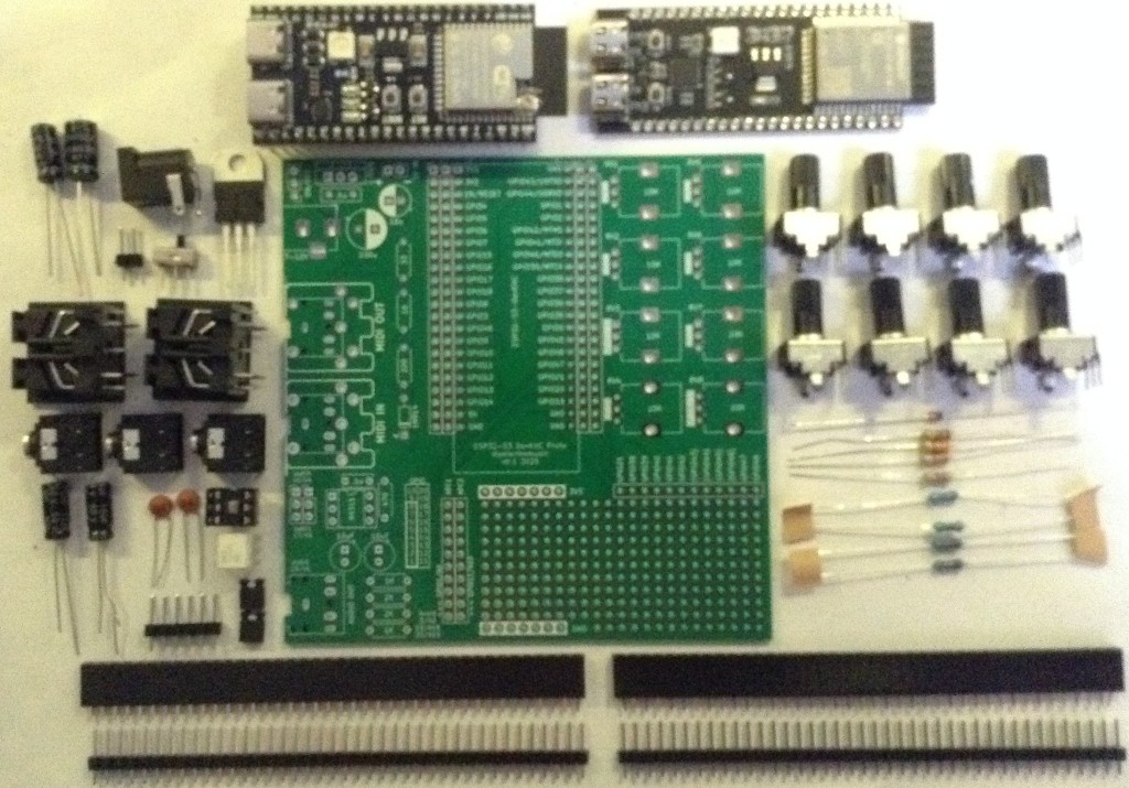
Bill of Materials
Each circuit module is effectively optional. The position of the 22-way headers will depend on which type of module is used. The clone versions are 1 pin row wider than the official version.
There are some solder-bridge configuration options too, which will be discussed later.
Build Steps
Taking a typical “low to high” soldering approach, this is the suggested order of assembly:
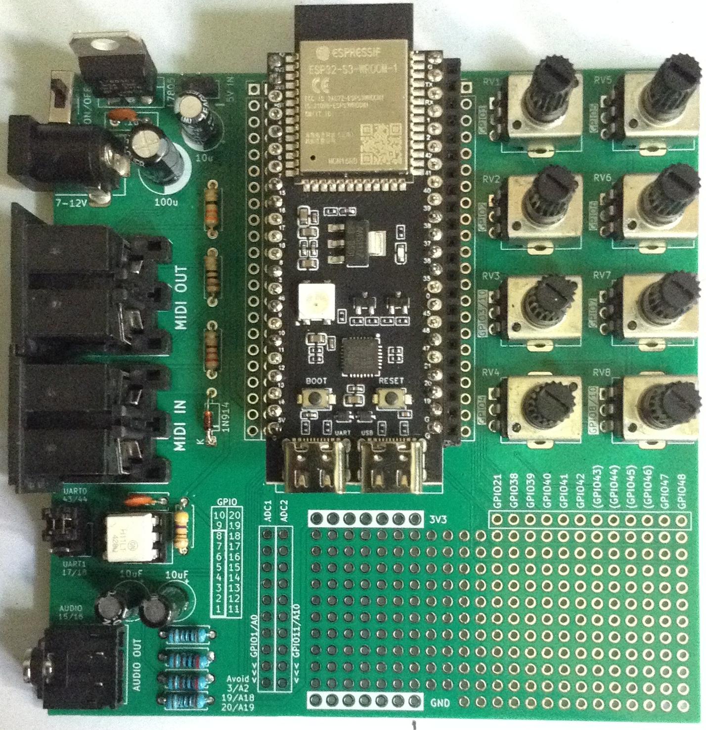
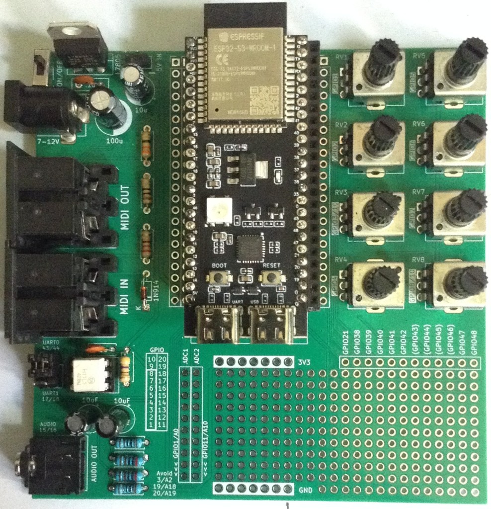
Here are some build photos for the MIDI DIN version of the board. If using MIDI TRS sockets, then these can be installed at the same time as the audio socket.
If using 22-way headers for the DevKit, then the position will depend on which type of DevKit module is being used. In the photo below, I’ve installed 3 sets of 22-way headers to allow me to use either a clone or official module.
The remaining components can almost be installed in any order that makes sense at the time.
Once the main build is complete, two additional capacitors are required for the audio PWM output circuit. Two 33nF capacitors should be soldered across the 1K resistors. This is probably best done on the underside of the PCB as shown below.
Ignore the red patch wire. I managed to cut through a track whilst clipping the excess leads after soldering.
Configuration Options
The following are configurable and can be set by using pin headers and jumpers; solder bridges; or possibly wire links.
Testing
I recommend performing the general tests described here: PCBs.
WARNING: The DevKit can be powered from either the USB sockets or the new power circuit, but not both at the same time.
The sample application section includes some simple sketches that can be used to test the functionality of the board.
PCB Errata
There are the following issues with this PCB:
Enhancements:
Sample Applications
Analog Potentiometers
The following will read all 8 pots and echo the values to the serial monitor.
void setup() {
  Serial.begin(115200);
}
void loop() {
  for (int i=0; i<8; i++) {
    int aval = analogRead(A0+i);
    Serial.print(aval);
    Serial.print("\t");
  }
  Serial.print("\n");
  delay(100);
}
Audio PWM Output
The following will output a 440 Hz sine wave on the PWM channel on GPIO 15. Change to 16 to see the other one.
int pwm_pin = 15;#define NUM_SAMPLES 256uint8_t sinedata[NUM_SAMPLES];#define PWM_RESOLUTION 8#define PWM_FREQUENCY 48000#define TIMER_FREQ 10000000#define TIMER_RATE 305#define FREQ2INC(f) (f*2)uint16_t acc, inc;void ARDUINO_ISR_ATTR timerIsr (void) { acc += inc; ledcWrite (pwm_pin, sinedata[acc >> 8]);}hw_timer_t *timer = NULL;void setup () { ledcSetClockSource(LEDC_AUTO_CLK); for (int i=0; i<NUM_SAMPLES; i++) { sinedata[i] = 127 + (uint8_t) (127.0 * sin (((float)i * 2.0 * 3.14159) / (float)NUM_SAMPLES)); } timer = timerBegin(TIMER_FREQ); timerAttachInterrupt(timer, &timerIsr); timerAlarm(timer, TIMER_RATE, true, 0); ledcAttach(pwm_pin, PWM_FREQUENCY, PWM_RESOLUTION); inc = FREQ2INC(440);}void loop () { }I’m getting a pretty good signal with a 33nF filter capacitor, but the signal still retails some bias. I’m getting a Vpp of around 1.1V, but it swings from -380mV to +720mV on one channel and -200mV to +900mV on the other.
MIDI
Most of the MIDI monitors, routers and sending projects I have should work with the MIDI setup. In the default configuration, using UART0 (GPIO 43/44) for MIDI, that appears as Serial0 or the default MIDI configuration (more on serial ports on the ESP32S3 here: ESP32 S3 DevKit).
So the Simple MIDI Serial Monitor should just work and anything sent to the board should:
Here is the full test code:
#include <MIDI.h>

MIDI_CREATE_DEFAULT_INSTANCE();

void setup() {
  MIDI.begin(MIDI_CHANNEL_OMNI);
  pinMode (LED_BUILTIN, OUTPUT);
}

void loop() {
  if (MIDI.read()) {
    if (MIDI.getType() == midi::NoteOn) {
        digitalWrite (LED_BUILTIN, HIGH);
        delay (100);
        digitalWrite (LED_BUILTIN, LOW);
    }
  }
}
Note: as the MIDI is (probably) hanging of UART0 which is also routed to the USB “COM” port, it will be easier to upload via the USB “USB” port. This won’t clash with the MIDI circuitry on UART0.
Closing Thoughts
I seem to be having a run of “doh” moments with a few of these PCBs, but then that is the price I pay for taking shortcuts by only designing them in my head rather than prototyping them first!
But arguably, it is still a lot easier using a soldered PCB than attempting to build the various elements on solderless breadboard, so in a way that is what these prototypes are largely for.
So apart from the filter issue which is actually fairly easily solved, this seems to work pretty well.
Kevin
ESP32 S3 DevKit Experimenter PCB Design
This a version of the ESP32 WROOM Mozzi Experimenter PCB for the latest ESP32-S3 DevKitC board I’ve found.
For the background on the boards themselves, see my notes here: ESP32 S3 DevKit.
Warning! I strongly recommend using old or second hand equipment for your experiments. I am not responsible for any damage to expensive instruments!
If you are new to Microcontrollers, see the Getting Started pages.
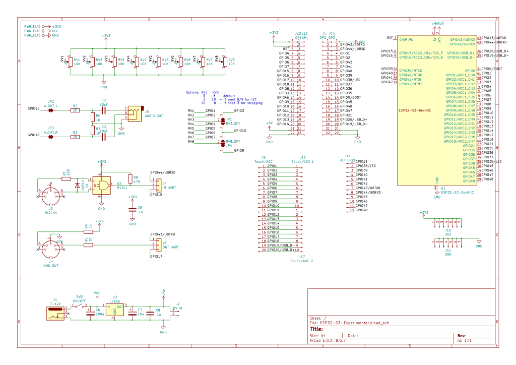
The Circuit
This is mostly just breaking out the pins of the ESP32S3 DevKitC to header pins, but there are a couple of additional features too:
One slight complication is the possibility that GPIO3 (ADC1_CH2) is required as a STRAPPING pin or that GPIO8 (ADC1_CH7) is required for I2C (more in the previous post) so there is a solder bridge option for either of them to switch over to GPIO10 (ADC1_CH9) instead.
The complete GPIO usage is as follows:
GPIO0On board BOOT buttonGPIO 1-8Potentiometer 1-8GPIO 10Optional replacement for GPIO 3 or 8GPIO 15, 16PWM audio outputGPIO 43, 44MIDI if UART0 is selectedGPIO 17, 18MIDI if UART1 is selectedGPIO 1-20Analog breakout area*GPIO 21, 38-49Digital breakout area*GPIO 38 or 48Onboard RGB LED* As already mentioned some of these have alternative or preferred functions.
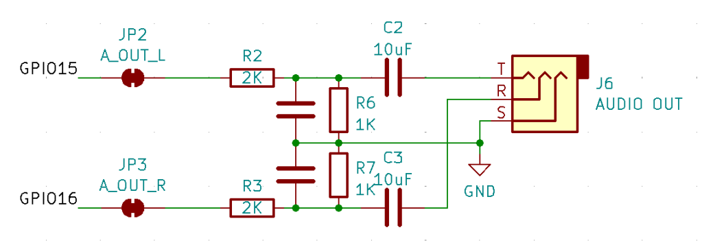
Audio PWM Output
I based this on the output circuit for my ESP32 WROOM Mozzi Experimenter PCB Design, but I was forgetting that the original ESP32 has a DAC and so only requires a potential divider to reduce the voltage levels and a capacitor to remove the DC bias.
The ESP32S3 does not have a DAC, so the output will have to be via PWM if no external DAC is added. This means this output circuit really needs a low-pass filter to smooth out the pulses from the PWM signal.
That hasn’t been included in the design, but can be implemented by adding capacitors across the terminals of the 1K resistors, as shown below.
Following the discussion from Arduino PWM Output Filter Circuit, we can see that a 2K/1K potential divider can (loosely) be treated as a ~666K resistor for the purposes of a low-pass filter calculation. So this gives me various options in terms of capacitor size as follows.
ResistorCapacitorRoll-off frequency666K10nF24 kHz666K33nF7 kHz666K68nF3.5 kHz666K100nF2.4 kHzThe greatest smoothing will come with the lowest cut-off, but 2.4kHz or 3.5kHz will limit the higher audio frequencies somewhat. But a 10nF might not give me enough smoothing.
It will also depend somewhat on the PWM frequency chosen. The higher, i.e. above the audio frequency range required, the better.
I’ll start with adding 33nF and see how that looks then might change with some experimentation.
If an external DAC is used, then there are solder jumpers provided that can be broken to disconnect this part of the circuit anyway.
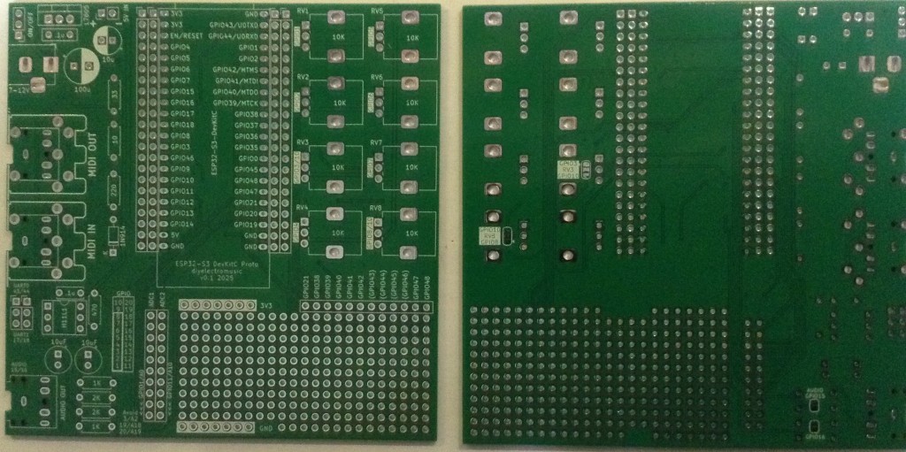
PCB Design
I initially considered only breaking out GPIO pins that weren’t being used for additional functions, but then decided I’d just break them all out alongside the prototyping area. Any pins that might be problematic or have an existing function on the board are labelled in brackets – e.g. (GPIO 43).
The solder jumpers for the GPIO/ADC choices are on the underside of the board.
As previously mentioned, the headers are arranged such that it will support the official DevKitC or the slightly wider clones.
The jumper for UART selection for MIDI can serve as a “disable MIDI to allow use of the serial port” function too if required.
There is also a twin jumper option for direct 5V input instead of going via the barrel jack and regulator.
Closing Thoughts
The omission of the capacitors in the PWM filter is a small annoyance, but it is relatively easily fixed.
Apart from that, there is a fair bit included on this board. It should serve as a good platform for further experimentation.
Kevin
ESP32 S3 DevKit
Having played a bit with ESP32-S3 now, in the of the Waveshare Zero format boards, I’d quite like to have a version of the ESP32 WROOM Mozzi Experimenter PCB for the latest ESP32-S3 DevKitC board I’ve found.
This is the introductory post that is my “notes to self” as I get to know the boards.
Warning! I strongly recommend using old or second hand equipment for your experiments. I am not responsible for any damage to expensive instruments!
If you are new to Microcontrollers, see the Getting Started pages.
ESP32-S3 DevKitC Boards
There are a couple of ESP32-S3 official DevKits, in addition to the huge range of third party boards from the likes of Waveshare, Adafruit, and so on of course.
The main references for these boards are:
Note: although the C and M DevKits both have 44 pins and very similar functionality, the actual pinouts for the two boards are quite different. On the face of things, it looks like the pinout for the M version seems a bit more logical to me than the C version, but I’ve ended up with C boards, so that is what I’m going with! Much of what follows is applicable to both though.
It is also worth noting that I was looking at the ESP32-S3 as a possible replacement for the original ESP32 in my Educational DIY Synth Thing. But in terms of general features, the ESP32-S3 and ESP32 are actually pretty similar.
From the comparison here, here are some key features listed:
ESP32ESP32-S332-bit LX632-bit LX7single or dual coredual core240MHz (one variant at 160MHz)240MHz520KB SRAM512 KB SRAM448 KB ROM384 KB ROM0MB, 2MB, 4MB Internal Flash0MB, 8MB Internal FlashUp to 16MB External FlashUp to 1GB External FlashUp to 8MB External RAMUp to 1GB External RAMMost of the peripherals are pretty similar too.
So the key difference is the switch from LX6 to LX7. As both support a single-precision floating point unit, and up to 240MHz operation in dual core modes, I’m not sure what the enhancement is at the moment.
One difference on Wikipedia is that the LX7 has “added instructions to accelerate machine learning applications” and it appears that there is a specific library that makes use of these instructions: ESP-DL. But I’ve not seen if any of this is likely to help me with audio.
I should also note that the original ESP32 is the only chip in the architectural family (as far as I can see) with an integrated DAC. There is certainly no DAC with the ESP32-S3.
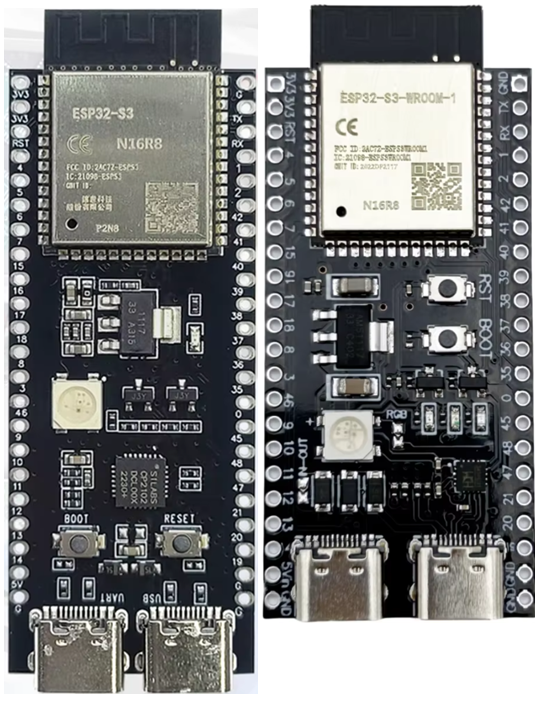
I was determined to go with the official ESP32-S3 DevKitC board this time. But on my first attempt I managed to end up with a very close clone! I have now have two variants as shown below. The original is on the left and the clone on the right.
The clones are very similar to the original but seem to have the following differences.
Physical Differences:
Electrical Differences:
Documentation for the original board: https://docs.espressif.com/projects/esp-dev-kits/en/latest/esp32s3/esp32-s3-devkitc-1/user_guide.html
Documentation for the clone: https://github.com/vcc-gnd/YD-ESP32-S3/tree/main/5-public-YD-ESP32-S3-Hardware%20info
At least the pinouts for the two modules seem the same, apart from the fact that one module is one-pin-header-row wider than the other.
ESP32-S3 DevKitC-1 GPIO Use
Strapping pins are used to set the configuration of the ESP32-S3 on power up. For details of the strapping pins and their use, see Section 4 in the ESP32-S3-WROOM-1 guide. The summary, and default settings for the ESP32-S3, is as follows:
GPIO0BOOT modeWeak pull-up to 1SPI bootGPIO3JTAG signal sourceFloatingEFUSE_STRAP_JTAG_SEL=0; GPIO3 ignored.Working through the datasheets, schematics and online guides, as far as I can make out the following GPIO pins all have an expected use on the DevKitC-1 boards, which can limit their use for general projects.
GPIOUse0, 3, 45, 46ESP32-S3 Strapping pins as described above.15, 16Optional: can be used to connect an external oscillator – not used on these boards.19, 20USB OTG port data connection35, 36, 37Onboard SPI flash memory43, 44UART0 connection to USB serial chip47, 48If a N16R16VA module (16MB Flash, 16MB PSRAM) is used then these pins operate at 1.8V.38 or 48WS2812 compatible RGB LEDTaking account of all the above, this leaves the following GPIO pins probably available for use in projects:
GPIO Range#PinsNotes1-22GPIO, Touch, ADC4-1613GPIO, Touch, ADC17-182GPIO, Touch, ADC, UART119-202GPIO, USB, ADC211GPIO381GPIO, LED on official board39-424GPIO, JTAG43-442GPIO, UART0471GPIO*481GPIO*, LED on clone board (can be disabled)So this would hopefully give me access to 19 GPIO that could act as analog inputs and a further 7 GPIO in addition to two for RX/TX.
This assumes that GPIO 47 and 48 not operating with an SPI flash configuration that means they will run at 1.8V. For the modules I have I’m using a ESP32-S3-N16R8 module so this should be fine as this only applies to the N16R16VA variants of the modules.
In terms of functions, the way the ESP32-S3 supports GPIO multiplexing means that any of these could be configured for I2C or I2S, and they all support PWM outputs.
For a more detailed discussion of the restrictions, see https://github.com/atomic14/esp32-s3-pinouts
EPS32-S3 and Arduino
Serial Ports
There are several options for serial ports:
These map onto the following serial options in Arduino (see cores/esp32/HardwareSerial.h):
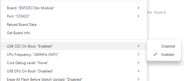
DeviceArduino DeviceArduino aliasNative USBUSBSerialSerial (if ARDUINO_USB_CDC_ON_BOOT set)USB via UART0Serial0Serial (if ARDUINO_USB_CDC_ON_BOOT not set)UART0Serial0UART1Serial1There is a build option that determines whether the loaded code includes a USB comms device or not.
If this isn’t set (i.e. “disabled”) then Serial goes to UART0 and the serial monitor has to be connected to the “COM” USB port.
If this is set (i.e. “enabled”) then Serial goes to USBSerial and the serial monitor can be connected to the “USB” USB port.
Note: there is some ESP32 start-up debug information that will always go to UART0 on boot regardless of this setting.
Analog Input
One quirk of the ESP32 Arduino environment and the ADC mapping means that the ADCs are mapped as follows:
This can be seen in the board definitions file for the Arduino ESP32 core: https://github.com/espressif/arduino-esp32/blob/master/variants/esp32s3/pins_arduino.h
Specific GPIO
We can also see the following from pins_arduino.h:
We can also see a series of Tn pin definitions for the touch pins:
RGB and LED_BUILTIN
Also, whilst perusing the same file, I noticed the following comment:
// Some boards have too low voltage on this pin (board design bug)
// Use different pin with 3V and connect with 48
// and change this setup for the chosen pin (for example 38)
#define PIN_RGB_LED 48
// BUILTIN_LED can be used in new Arduino API digitalWrite() like in Blink.ino
static const uint8_t LED_BUILTIN = SOC_GPIO_PIN_COUNT + PIN_RGB_LED;
#define BUILTIN_LED LED_BUILTIN  // backward compatibility
#define LED_BUILTIN LED_BUILTIN  // allow testing #ifdef LED_BUILTIN
// RGB_BUILTIN and RGB_BRIGHTNESS can be used in new Arduino API rgbLedWrite()
#define RGB_BUILTIN    LED_BUILTIN
#define RGB_BRIGHTNESS 64
This is recognising that pin 48 was used by default for the RGB LED, but because of the possibility of pins 47 and 48 being configured for 1.8V operation for certain SPI flash memory configurations, means that it doesn’t work in some cases. Presumably this is why the official boards now use pin 38 for the RGB LED instead.
Note, I don’t know why LED_BUILTIN = SOC_GPIO_PIN_COUNT + PIN_RGB_LED, but I’ve seen elsewhere, in cores/esp32/esp32-hal-rgb-led.c:
#ifdef RGB_BUILTIN
  pin = pin == RGB_BUILTIN ? pin - SOC_GPIO_PIN_COUNT : pin;
#endif
The provided BlinkRGB.ino example works fine with the official board and my clone. Both boards are configured as follows:
And using Serial.print for PIN_RGB_LED confirms that the RGB is on GPIO 48 for both my boards.
I2C GPIO
In terms of I2C, it is possible to select which pins to use, if the defaults (8, 9) are not desired. to do this, just pass some pin numbers into the Wire.begin call as follows:
Wire.begin(I2C_SDA, I2C_SCL);
Note that this is different to how this is done on a RP2040 which has its own setSDA() and setSCL() functions. At least in the unofficial core. I don’t know if this is even possible with the “official” RP2040 Arduino core, but I’m getting off-topic…
Closing Thoughts
For some reason, from what I’d read I was expecting an obvious leap in performance moving from an ESP32 to a ESP32S3, but now I’m not so sure it will make much difference.
I’ll just have to give things a go and see what happens!
Kevin
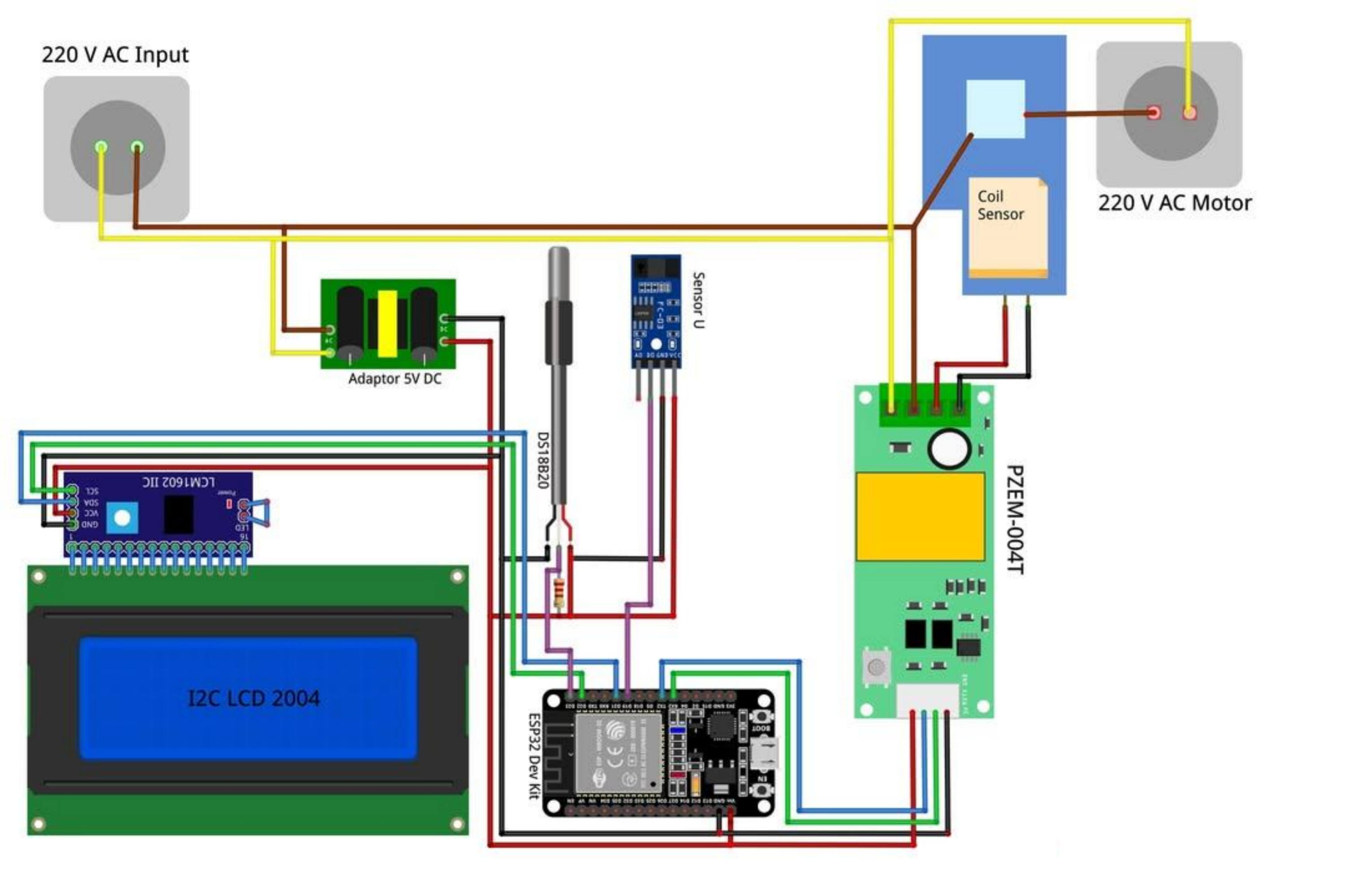
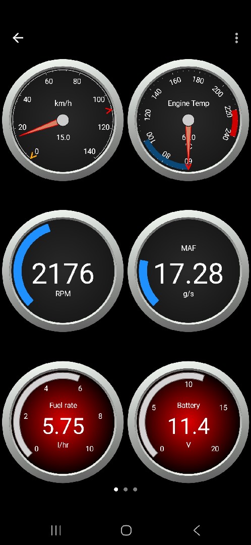
Monitoring RPM Speed, Temperature and Estimation of KWH Consumption Costs on IOT-Based Single Phase Induction Motors with ESP32
ESP32 eBooks 📚
https://bokfive.com/esp32
For more follow @bokfive ✅
#ESP32 #ESP32S3 #Arduino #IoT #LoRa #LoRaWAN #LoRa32 #bokfive
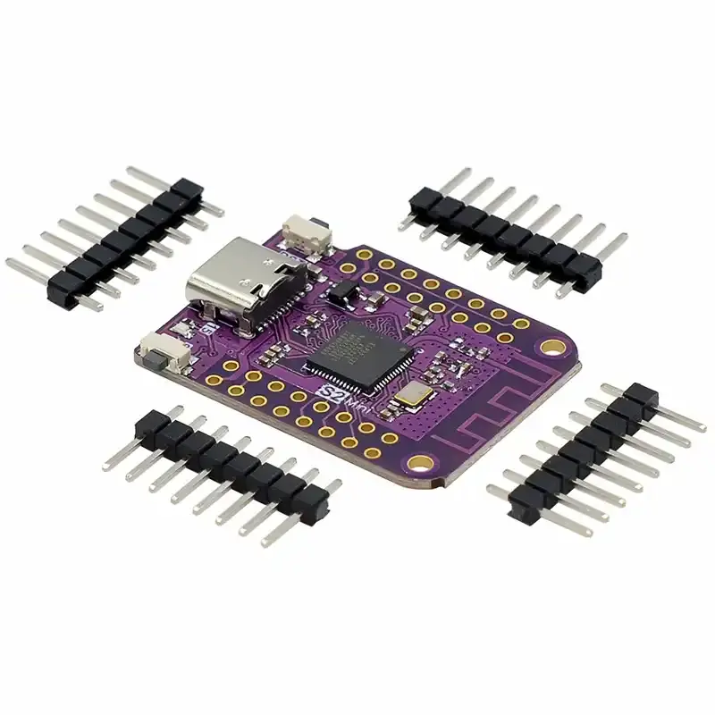
Cmxelcs ESP32 S3 Development Board, IOT Wifi Module
Development Board MCU Number:ESP32-S2FN4R2 WIFI IC Type-c USB
I/O Pin:27
PCB Size:34*25.5mm
Supports:ADC DAC I2C SPI USRT USB OTG
Packing List:
ESD Packing
Customized hardware list is provided,contact us to talk details.View our company site here to know more about our product category. #esp32s3 #esp32s3board #esp32s3price #esp32s3devboard #espressifesp32s3
https://www.cmxelcs.com/product/iot-esp32-s3-development-board/
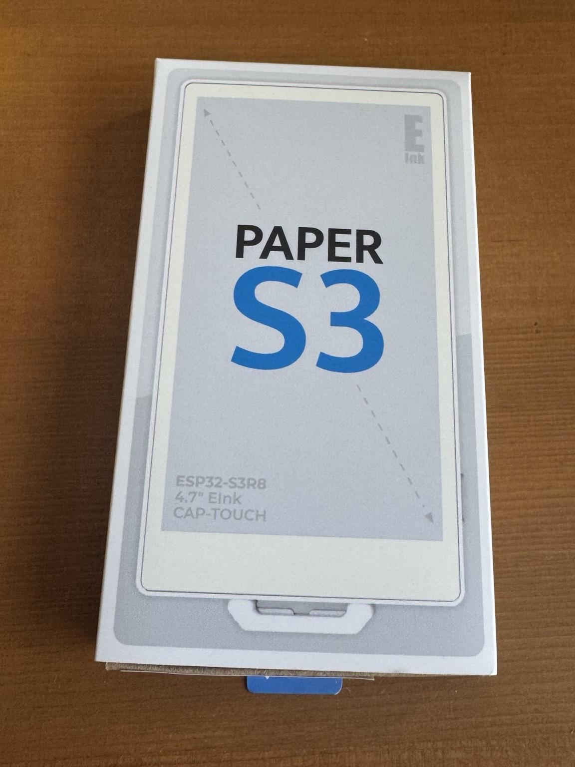
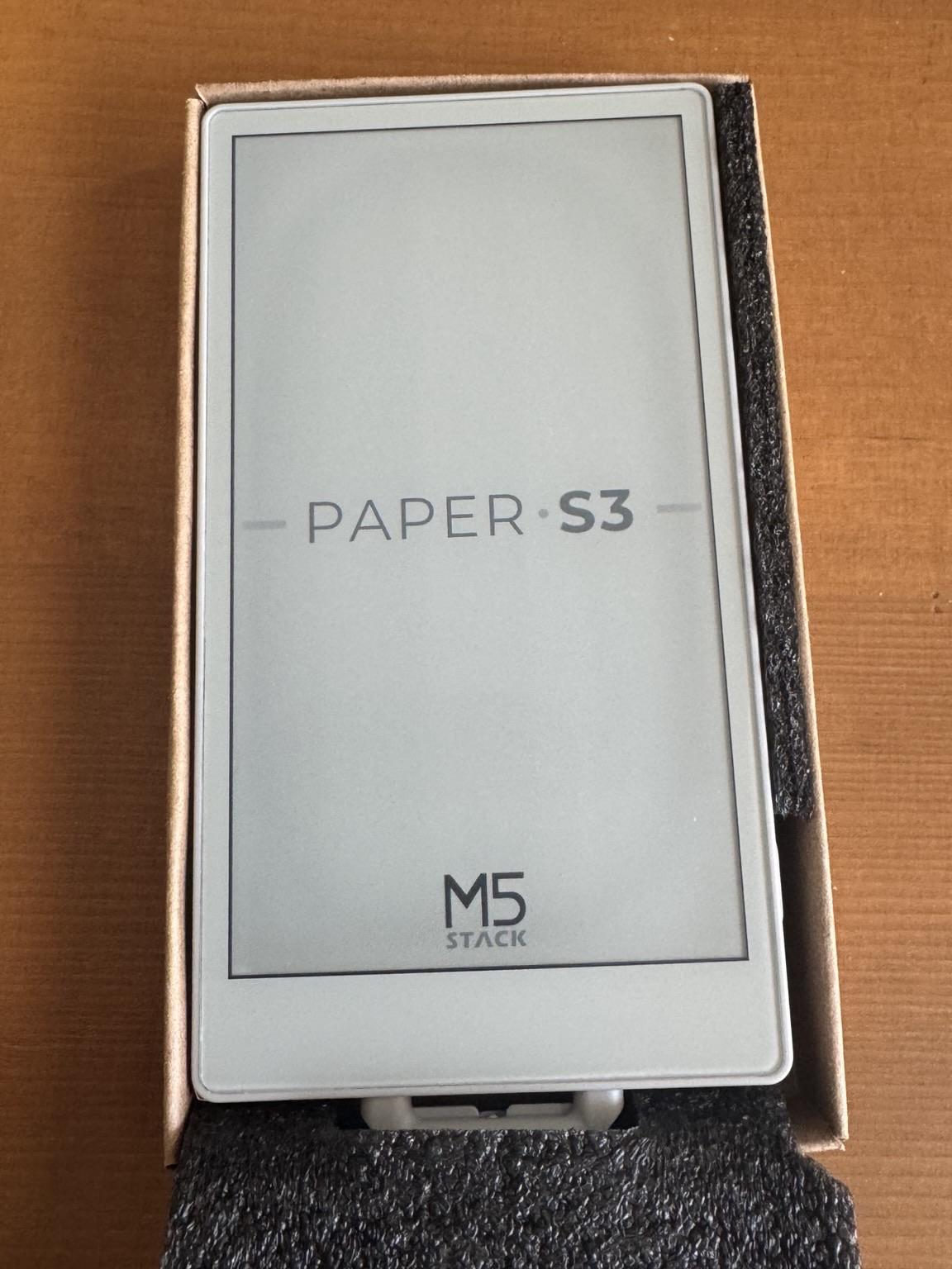
Anyone playing with #ink #epaper #esp32 ? Complete noob here. Where do you hang out? I want to see what you’re all doing? :) #M5Paper #M5PaperS3 #ESP32S3
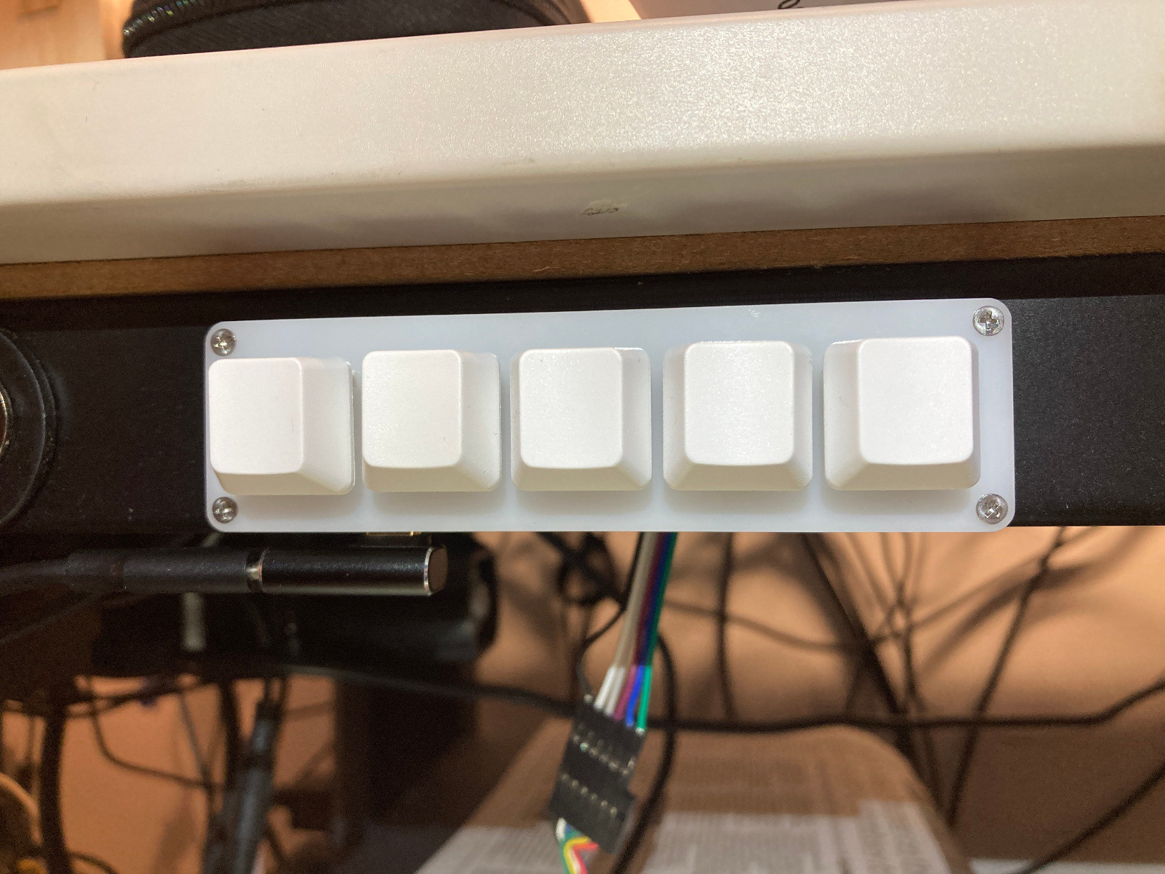
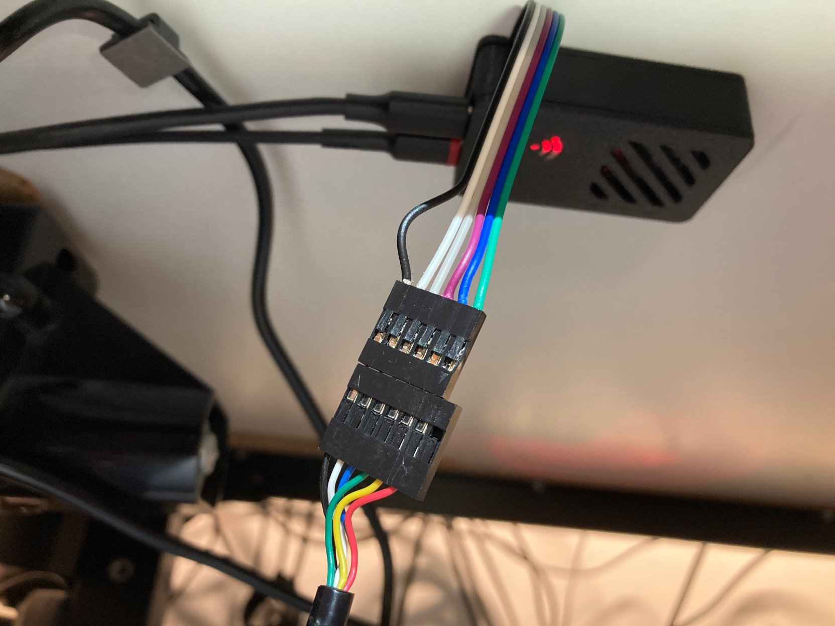
It's been a while since I did an #electronics #hobby #project / #maker thing (pandemic/house moves), but I'm quite happy with this: https://hackaday.io/project/202951-desk-controls-replacement I reused a 'broken' height-adjustable desk and got to mess about with some USB Host on an #esp32s3 and tried out ESP-IDF while I was at it. I think I prefer it to platform.io ...
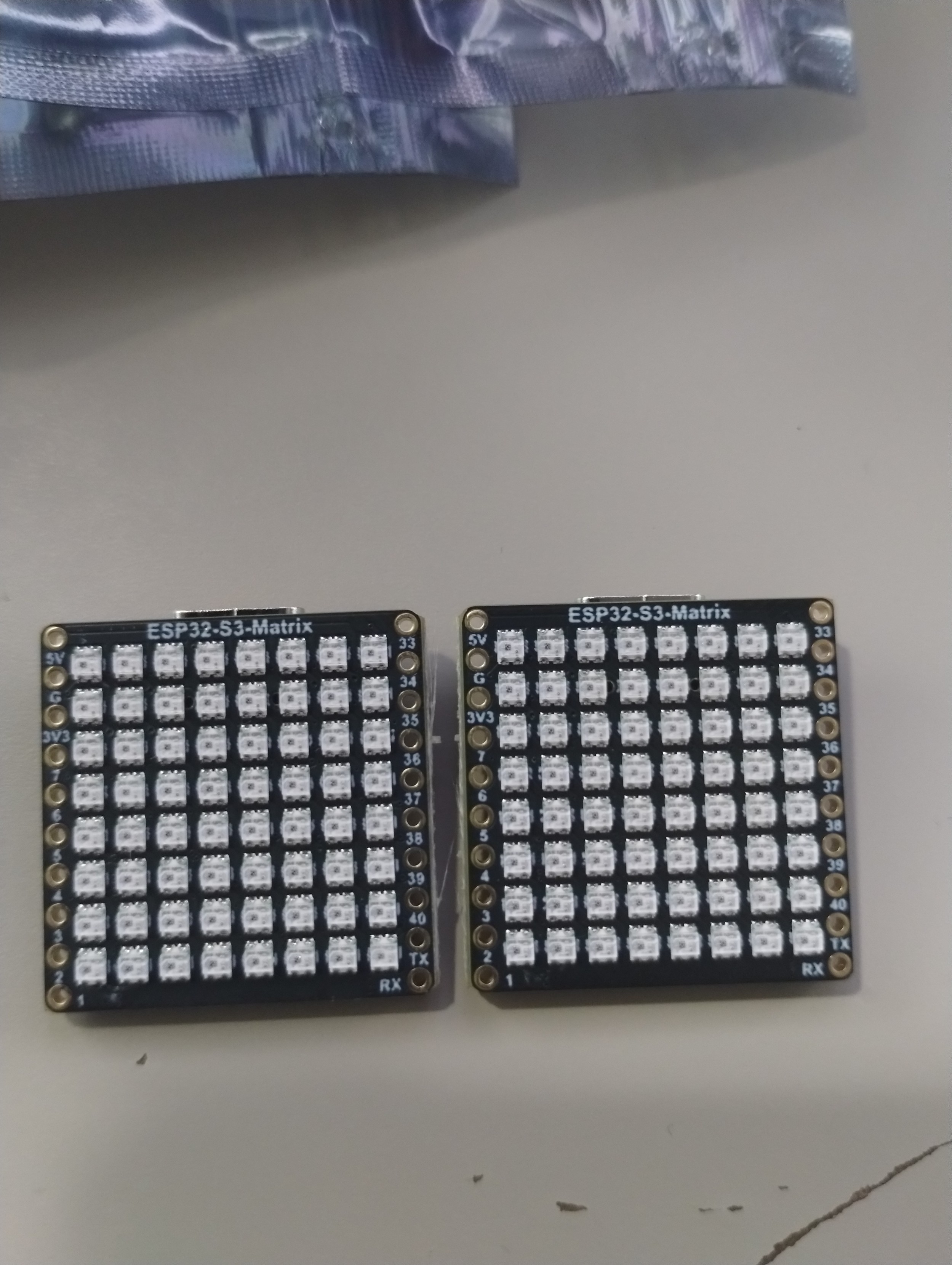
Saw this project on #Instructables from #Moononournation https://www.instructables.com/IoT-Emoji-Sign-V2/
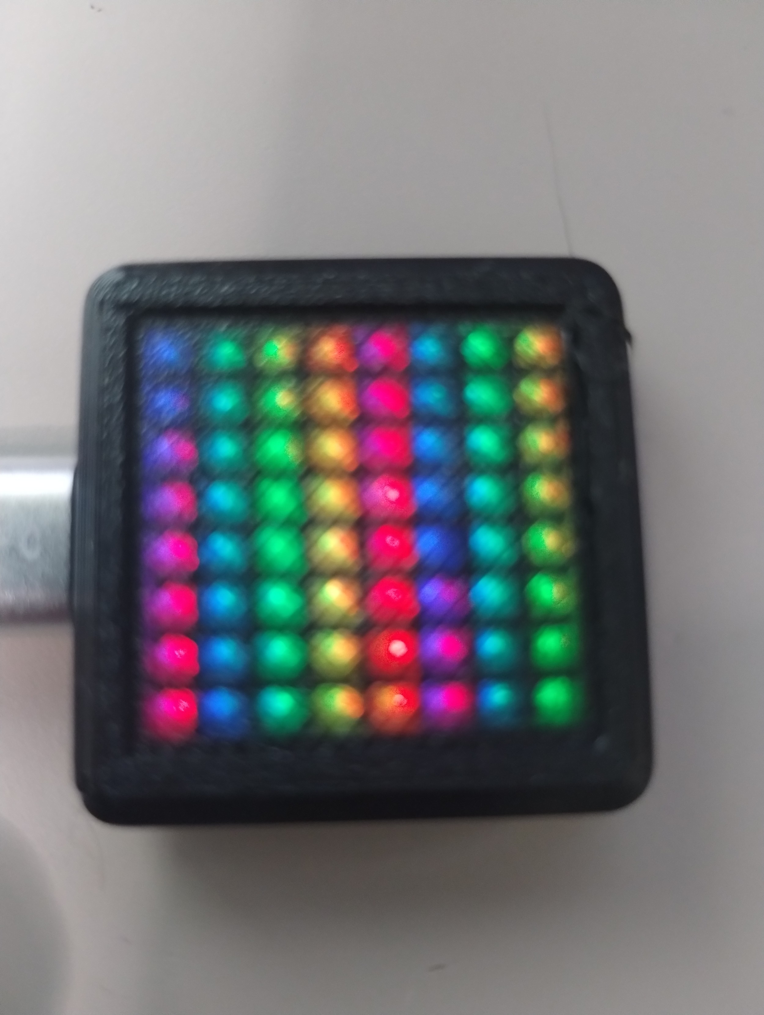
It's a fun project, but I was more interested in the 8x8 #Neopixel #Matrix
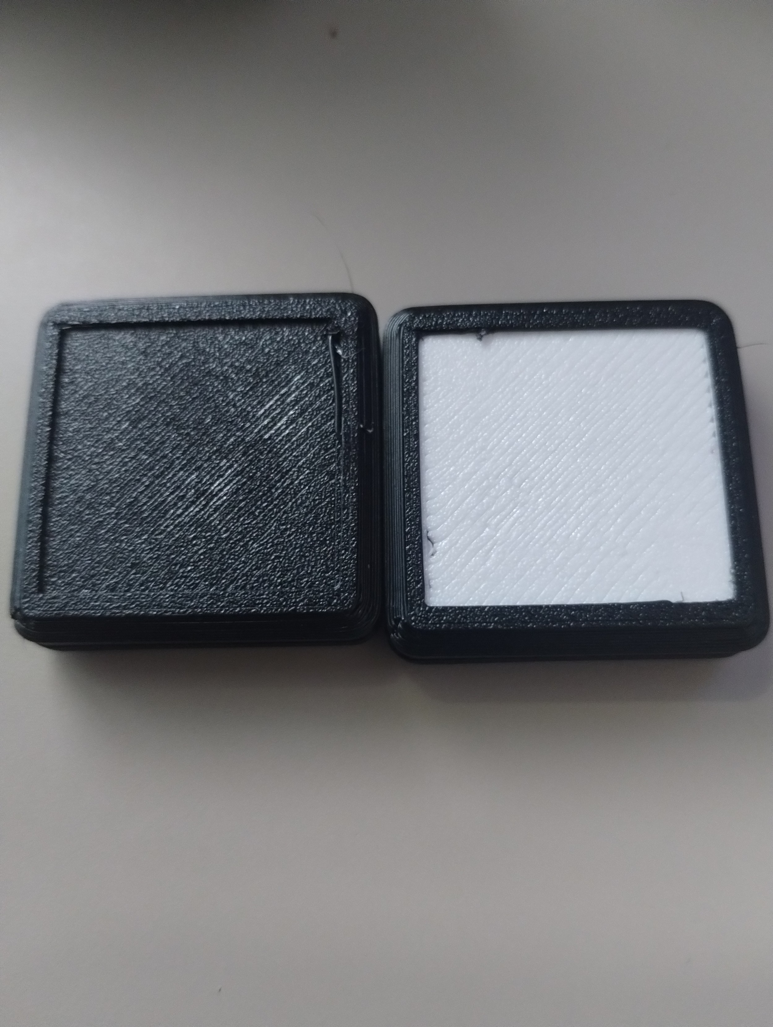
So I bought a couple of the #Waveshare #ESP32S3 8x8 boards, and printed out a couple of cases.
The boards work really well - I had an idea in mind when I ordered them, but now I forgot what I wanted to do with them.... I guess I'll make an #emjoi #display after all..... LOL
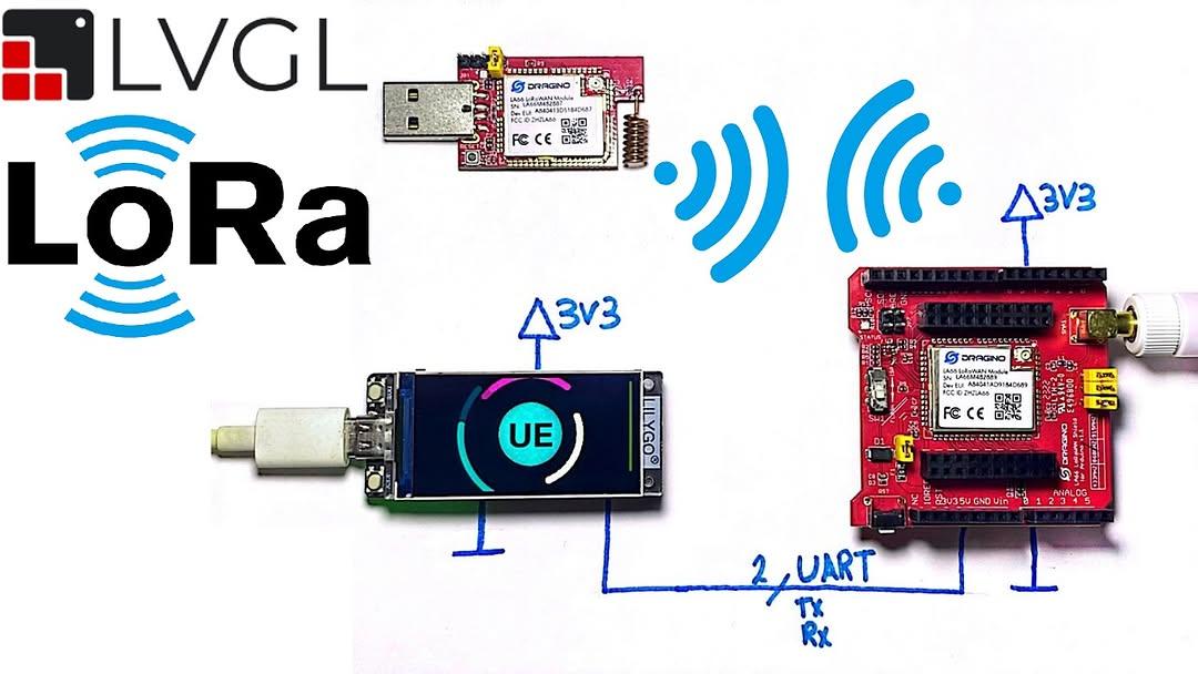
In this tutorial I am sharing with you guys my experiment with LA66 LoRaWan module from Dragino. I have interfaced the module using ESP32S3 MCU.
https://youtu.be/dV8yROPrPJw
ESP32 eBooks 📚
https://bokfive.com/esp32
For more follow @bokfive 🌟
#ESP32 #ESP32S3 #Arduino #IoT #LoRa #LoRaWAN #LoRa32 #bokfive
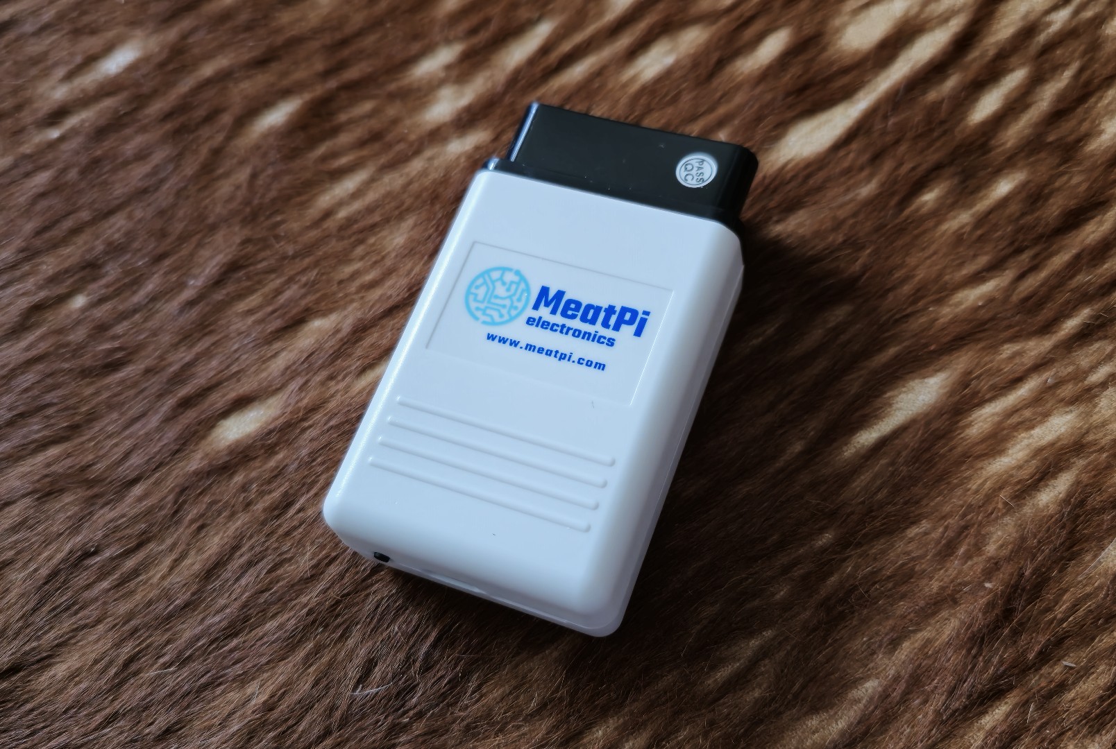
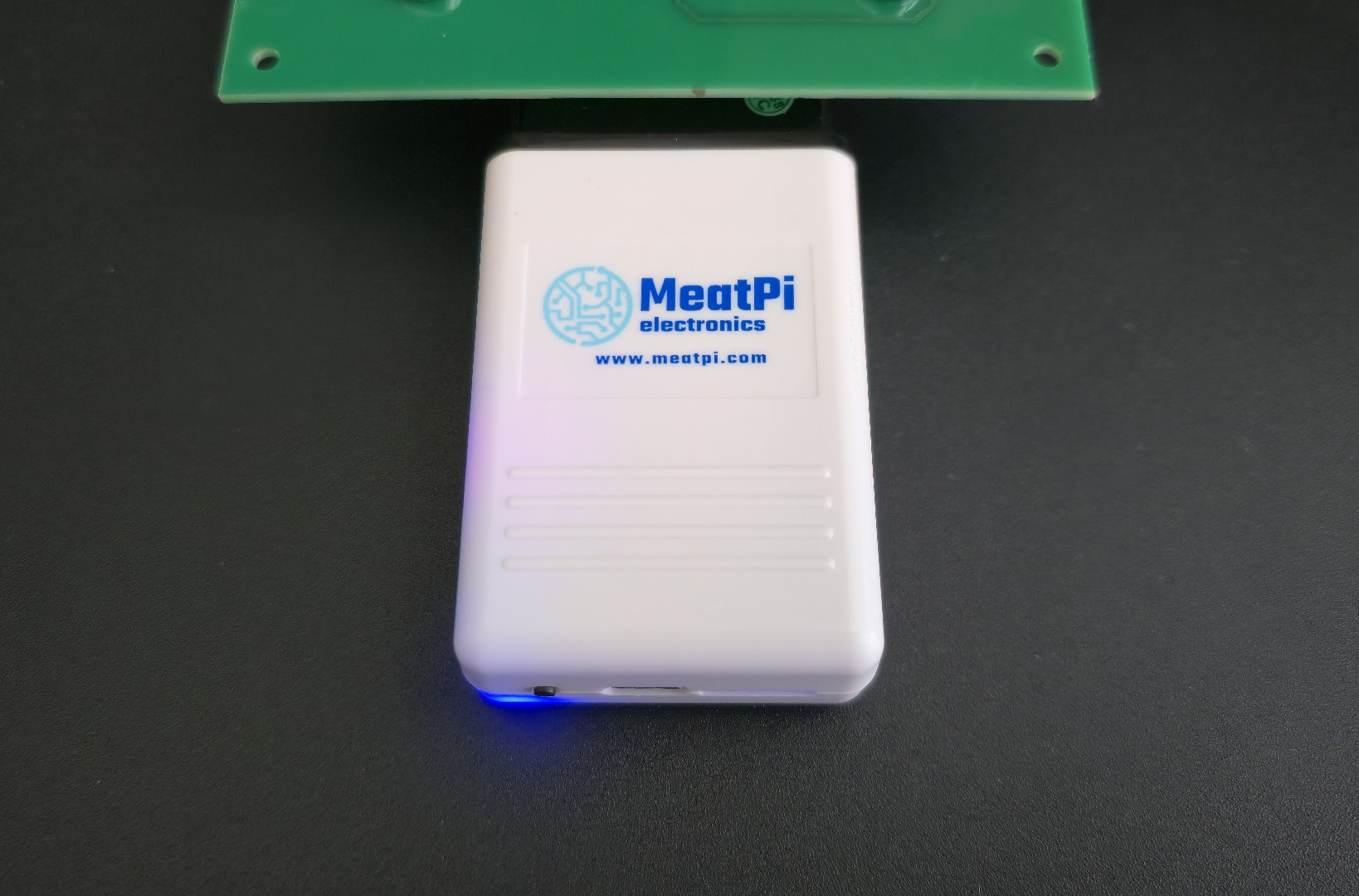
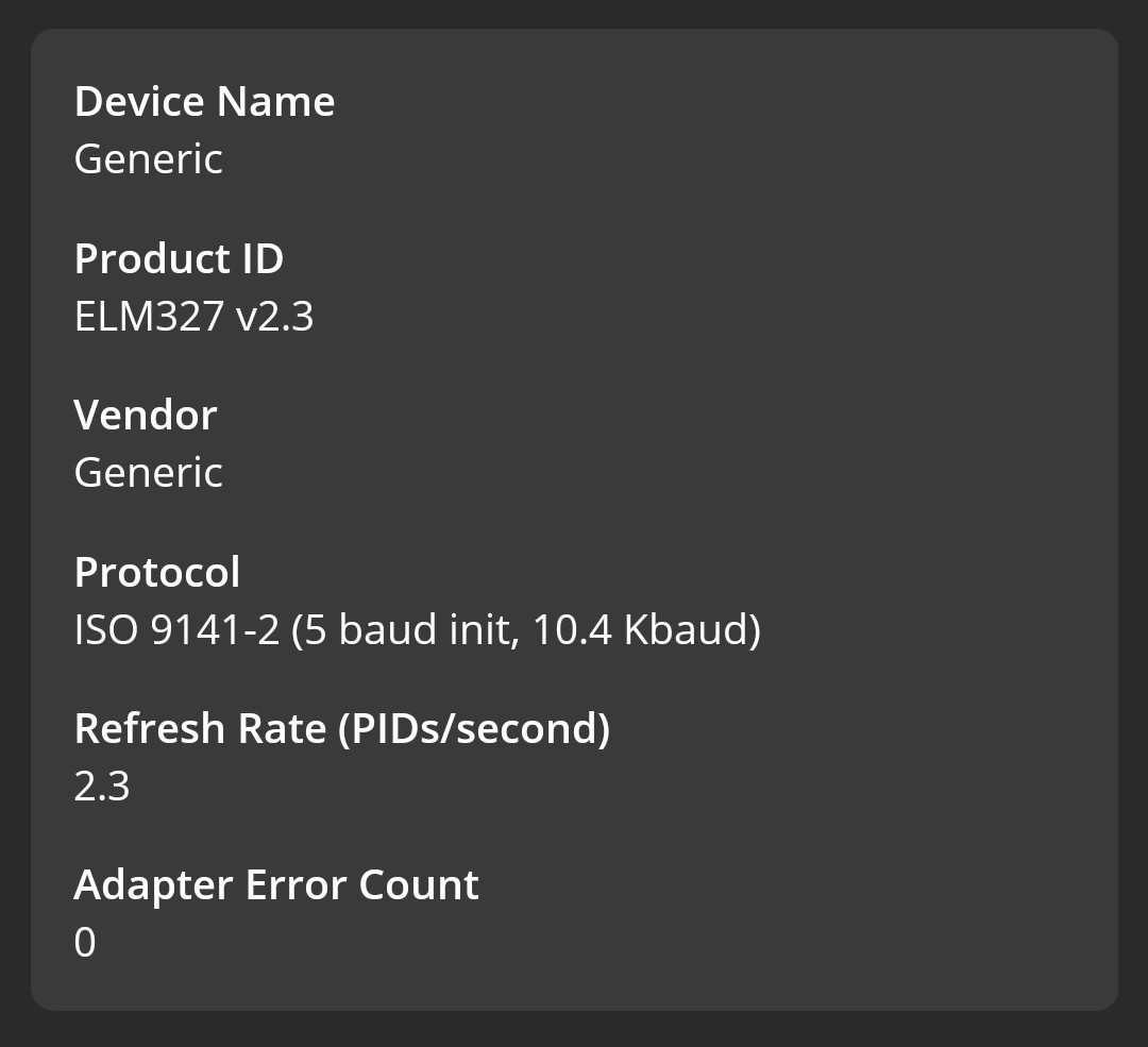
My first WiFi based OBD-2 car diagnostic tool - WiCAN PRO. It is based on ESP32-S3 platform and runs open source firmware.
As usual, testing on :obd2: simulator first :blobcatnerd:
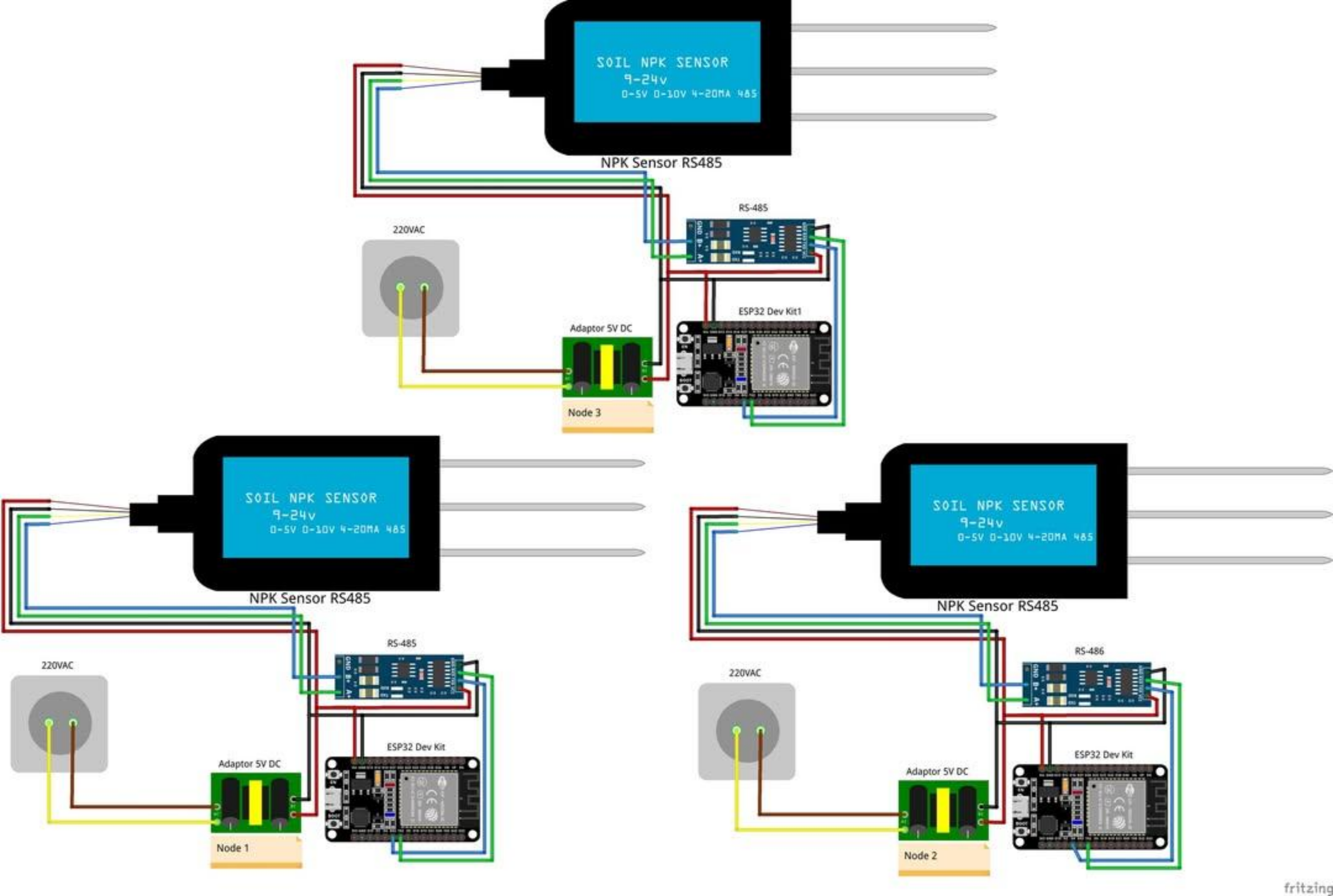
Soil Nutrient Monitoring System Using NPK Sensors Based on Wireless Sensor Network (WSN) and IOT
ESP32 eBooks 📚
https://bokfive.com/esp32
For more follow @bokfive 🌟
#ESP32 #ESP32S3 #Arduino #IoT #LoRa #LoRaWAN #LoRa32 #bokfive
Monitoring RPM Speed, Temperature and Estimation of KWH Consumption Costs on IOT-Based Single Phase Induction Motors with ESP32
ESP32 eBooks 📚
https://bokfive.com/esp32
For more follow @bokfive 🌟
#ESP32 #ESP32S3 #Arduino #IoT #LoRa #LoRaWAN #LoRa32 #bokfive

Duppa I2C MIDI Controller – Part 4
This is revisiting my Duppa I2C MIDI Controller this time using a Waveshare Zero format device.
Warning! I strongly recommend using old or second hand equipment for your experiments. I am not responsible for any damage to expensive instruments!
If you are new to Arduino, see the Getting Started pages.
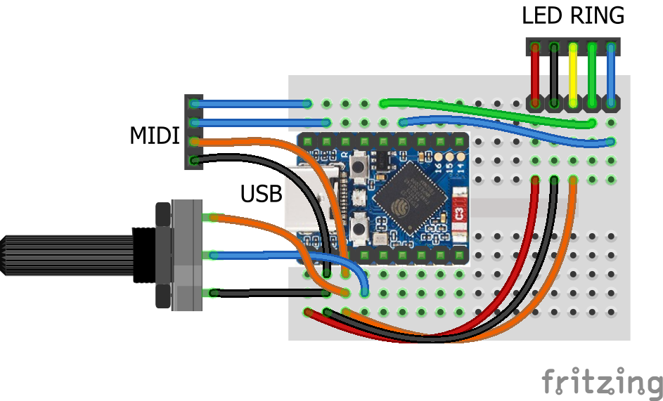
Parts list
Waveshare Zero, Duppa LED Ring, Potentiometers
I’m planning on being able to use any Waveshare Zero format board that I have (so that includes ESP32-S3, ESP32-C3 and RP2040) with the Duppa Ring so that means finding common pins to support I2C.
From the various pinouts (see Waveshare Zero, Pimoroni Tiny, and Neopixels) I can see I can use two pins in the bottom right-hand (with the USB connector at the top) corner of the board.
I’ll also need an analog connection and potentially connecting RX/TX to MIDI.
The various pins I’ll be using are as follows:
PinFunctionESP32-S3ESP32-C3RP204015V2GND33V34ADCGP1GP0GP29/A313SCLGP10GP9GP514SDAGP11GP10GP417RXGP44GP20GP118TXGP43GP21GP0Note, I’m not using physical pins 11 and 12, even though they also support I2C, as for the RP2040, these are on I2C bus 1, not 0 (see note later).
As the Pimoroni Tiny2040 is largely compatible too, that could also be used, but it will be physical pins 11 and 12, corresponding to GP5 and GP4, and 15 and 16 for GP1, GP0 (RX,TX).
The LEDs on the LED ring are powered from 5V, which comes directly off the Waveshare Zero USB port. The logic “VIO” is powered from 3V3.
The Code
I2C LED Ring
As the I2C pins to be used are configurable, this means changing the Duppa example code (and any other Arduino code) to initialise the I2C bus on specific pins as follows:
Wire.begin(11,10);    // SDA, SCL for ESP32-S3
Wire.begin(10,9);     // SDA, SCL for ESP32-C3
Using the ESP32 Arduino Core, there is a specific board entry for the Waveshare Zero ESP32-S3. There isn’t one for the ESP32-C3 so I just used “ESP32C3 Dev Module”.
I used the Arduino core for RP2040 from here rather than the official core: https://github.com/earlephilhower/arduino-pico
But the I2C initialisation is a little different.
  Wire.setSDA(4);
  Wire.setSCL(5);
  Wire.begin();
If I’d have been using GP6 and GP7, then these would have required the initialisation of Wire1 rather than Wire with the RP2040 core.
Note: to use the serial port once a sketch has been loaded onto the board, requires the following to be set (via the Arduino Tools menu):
USB CDC On Boot -> Enabled
Once again, I’ve soldered the jumpers on the LED ring to enable pull-ups and set the address for S1 and S5, so that has to be changed in the demo code too.
Analog Potentiometer
In terms of analog read, the ESP32 has a resolution of 0..4095 compared to the Arduino’s 0..1023, so that has to be taken into account when calculating the MIDI CC values.
To do this, the reading has to be divided by the ratio of Pot Range / 128.
int newpot = algpot.avgeAnalogRead(PIN_ALG) / ((MAX_POT_VALUE+1)/128);
Serial MIDI
For these boards, the serial port has to be specified. There are different options depending on the board being used (more here).
To use the pins nominally designated as RX/TX on all of these boards, use:
// ESP32-S3 GP43,GP44 or ESP32-C3 GP20,GP21
MIDI_CREATE_INSTANCE(HardwareSerial, Serial0, MIDI);
// RP2040 GP1,GP0
MIDI_CREATE_INSTANCE(HardwareSerial, Serial1, MIDI);
It is a quirk of the RP2040 Arduino core that UART0 appears on Serial1 and UART1 on Serial2. Serial0 does not exist but USB is Serial (more here).
Also, for the RP2040 the pins can be changed prior to calling MIDI.begin() if required as follows:
Serial1.setRX(rxpin);
Serial1.setTX(txpin);
MIDI.begin();
MIDI USB
I want to make this a fairly stand-alone MIDI USB device, so for the ESP32 and RP2040 this means using the TinyUSB stack. There is an Adafruit library for Arduino that supports both and also works with the Arduino MIDI Library. References:
I’ve cribbed most of the code from: https://github.com/adafruit/Adafruit_TinyUSB_Arduino/blob/master/examples/MIDI/midi_test/midi_test.ino
And added the appropriate parts to my own midiSetup() and midiLoop() functions.
MIDI USB – ESP32-S3
For this to work on the ESP32-S3, the board settings (via the Arduino Tools menu) need to be changed as follows:
USB CDC On Boot -> Enabled
USB Mode -> USB-OTG (TinyUSB)
USB Firmware MSC On Boot=Disabled
USB DFU On Boot=Disabled
Naturally this means USB can’t be used for serial output anymore.
It also means that automatic sketch reset and download often didn’t work for me. It was quite normal to now have to use the BOOT and RESET buttons to get the ESP32 back into listening for a new sketch – not always, but also not uncommon. But this might be some serial port remapping weirdness that often occurs when the USB stack is running on the same microprocessor as the main code…
MIDI USB – RP2040
For the RP2040, the USB stack needs to be changed from the Pico SDK to TinyUSB, so in the Tools menu:
USB Stack -> Adafruit TinyUSB
There are some other RP2040 specific notes here, but I don’t believe they apply unless one is interested in rebuilding the core, default TinyUSB support directly.
USB MIDI – ESP32-C3
I don’t believe USB MIDI works on the ESP32-C3
Adafruit TinyUSB doesn’t seem to anyway and I haven’t looked into what the options might be yet.
Other Notes
I’ve left in all the conditional compilation from Duppa I2C MIDI Controller – Part 3 but for now am just working with potentiometer control.
Pretty much everything is configurable, but the most important config option is to specify the board at the top:
//#define WAVESHARE_ESP32S3
//#define WAVESHARE_ESP32C3
#define WAVESHARE_RP2040
I could probably auto detect from the build settings but for now, this will do.
Other options include GPIO pins, whether to include serial or USB MIDI (or both), and whether to enable MIDI THRU or not.
Closing Thoughts
This is the first go at getting my Duppa controller working on 3V3 Waveshare Zero format boards, and so far it looks pretty good.
For the ESP32-S3 and RP2040 being able to enable MIDI USB is particularly useful. I might see if I can support MIDI THRU across the interfaces, which might be handy for a built-in USB to serial MIDI converter, but for now MIDI THRU is on the same port only.
I’ve not tested this with encoders or the endless potentiometer, but in theory it ought to work. I’d have to add some conditional compilation for GPIO numbers if I want to keep the same physical pins again.
Kevin
#controlChange #duppa #endlessPotentiometer #esp32c3 #ESP32s3 #i2c #midi #potentiometer #rgbLed #rotaryEncoder #rp2040 #WaveshareZero

SparkFun BMV080 Arduino Library (1.0.1) for esp32/esp32s2/esp32s3/cortex-m33/cortex-m0plus/cortex-m4f by SparkFun Electronics
➡️ https://github.com/sparkfun/SparkFun_BMV080_Arduino_Library
The SparkFun Air Quality PM1/PM2.5/PM10 Sensor - BMV080 (Qwiic)is an ultra-small, fan-less air quality sensor for sensing particulate matter!
#Arduino #ArduinoLibs #esp32 #esp32s2 #esp32s3 #cortex-m33 #cortex-m0plus #cortex-m4f
SparkFun BMV080 Arduino Library (1.0.0) for esp32/esp32s2/esp32s3/cortex-m33/cortex-m0plus/cortex-m4f by SparkFun Electronics
➡️ https://github.com/sparkfun/SparkFun_BMV080_Arduino_Library
The SparkFun Air Quality PM1/PM2.5/PM10 Sensor - BMV080 (Qwiic)is an ultra-small, fan-less air quality sensor for sensing PM2.5 particulate matter! Within the enclosure is a breakout board that breaks out Bosch's B...
#Arduino #ArduinoLibs #esp32 #esp32s2 #esp32s3 #cortex-m33 #cortex-m0plus #cortex-m4f
readguy (1.4.2) for esp8266/esp32/esp32s2/esp32s3/esp32c3 by fsender
➡️ https://github.com/fsender/readguy
A free E-paper display driver library supports 16-level greyscale.
#Arduino #ArduinoLibs #esp8266 #esp32 #esp32s2 #esp32s3 #esp32c3
🔍📡 KY-010 Light Barrier Sensor
The KY-010 is an infrared-based sensor widely used in robotics and automation 🔥. It works simply: when an object passes between the emitter and receiver, it interrupts the light and sends a signal to the Arduino or any microcontroller! 💡👀
💡 Applications:
✅ Object counting 🚗
✅ Security systems 🔐
✅ Interactive projects ⚙️
Have you used it in your projects? 💬👇
ESP32 eBooks 📚
https://bokfive.com/esp32
#ESP32 #ESP32S3 #Arduino #IoT #LoRa #LoRaWAN #LoRa32 #bokfive
Muse_library (1.0.9) for esp32/esp32S3 by Raspiaudio
➡️ https://github.com/RASPIAUDIO/Muse_library
A library for the ESP MUSE devices (LUXE, PROTO, MANGA, RADIO) by Raspiaudio