#openEMS

2025-06-27

Simulating SMA connectors... #electronics #openEMS

A simplified SMA receptacle, under simulation.
2025-06-26

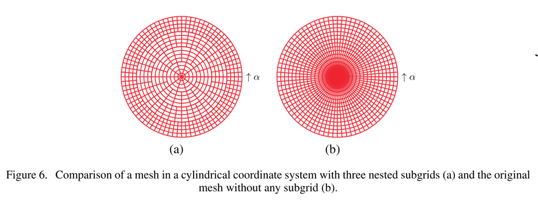
Simulating a coax cable in cylindrical coordinates has a funny problem. The mesh cell becomes progressively smaller in area or volume at you move closer to the singular origin, which is the region where the center conductor is located. So you spend an absolutely ridiculous amount of CPU cycles to calculate nothingness - there's no electric field inside a conductor ​:blobcatfacepalm:​ openEMS has a special "multigrid" mode to solve this problem. When it's enabled, it skips every other radial mesh line within the specified radius, and can be applied recursively too. #electronics #openEMS

Figure 6. Comparison of a mesh in a cylindrical coordinate system with three nested subgrids (a) and the original mesh without any subgrid (b).
2025-06-22

Finally got my new #openEMS simulation running after debugging it for days. #electronics

for task in task_list:
        # XXX: openEMS's Python binding contains bugs in the reset logic.
        # Thus, each new openEMS instance MUST be associated with a CSX
        # instance only ONCE via SetCSX(). Changing CSX via fdtd.SetCSX()
        # may cause segmentation faults and hard-to-debug erroneous
        # simulation results due to stale state.
        newfdtd = openEMS.openEMS()
        newcsx = CSXCAD.ContinuousStructure(CoordSystem=1)
        newfdtd.SetCSX(newcsx)

        task["csx"] = newcsx
        task["fdtd"] = newfdtd
2025-06-18

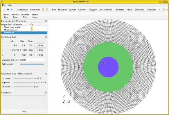
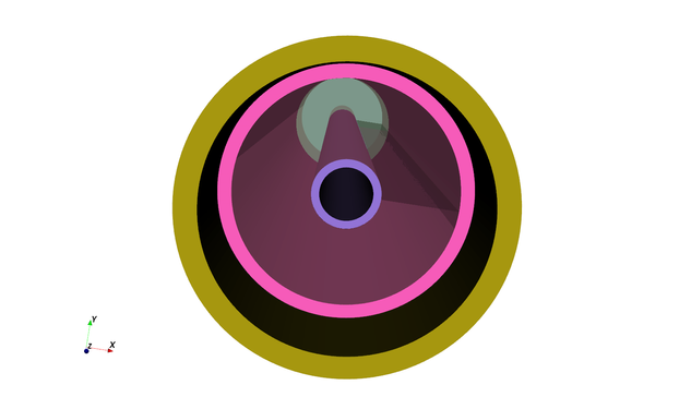
/me Trying to understand how to run #openEMS full-wave simulations in cylindrical coordinates instead. #electronics

3D model of a coax cable, constructed and meshed in cylindrical coordinates. Only the cross-section is shown, so it looks like polar coordinates.
hufnagel 🏳️‍🌈 🐧🔆Hufnagel@mastodon.de
2025-06-07

@crazy2bike
Hi, ist Goodwe nur der WR, und was sitzt denn da noch für ein Management System drauf für den Speicher? Oder macht der das mit?
Ich bastel nämlich grad an ähnlichen Themen mit #fenecon / #openems was die Datenpunkte angeht.
Doku ist eher überschaubar 😳

2025-06-06

Do you understand how #RF and #magnetics work? Any time I check out Sam Aldhaher's visualizations, I do just a bit better. We spoke on The Amp Hour this week about how to get started in #blender and build out visualizations using tools like #openems and #elmer_fem.

theamphour.com/695-making-the-

This episode was similar to the one I recorded with Katerina Galitskaya last year, who also does amazing visualizations. It's just SO useful to have people explaining RF with math and 3D models!

2025-04-30

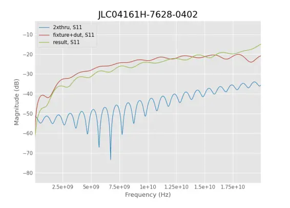
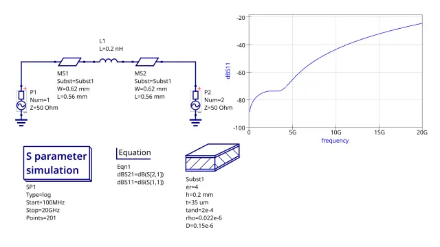
#openEMS simulation of 0402 AC-coupling capacitor parasitics. On a 4-layer board, with 0.2 mm from signal layer to plane. Interestingly, the parasitic capacitance of the mounting pads and the parasitic inductance of the capacitor forms an accidental matching network and compensated each other in this stackup, making it usable even at 20 GHz! You can see similar results without a full-wave solver in lumped circuit simulators, by modeling the mounting pads as two short microstrips, and inserting an 0.1 - 0.2 nH ESL in series. But I won't trust this result unless I can borrow a 20 GHz VNA somewhere, since it's extremely sensitive to parasitic modeling. Also, the magical effect disappears for a better 0.1 mm dielectric, often preferred for lower loop area and lower crosstalks. #electronics

openEMS's simulatios S-parameters of 0402 capacitor on JLCPCB's JLC04161H-7268-0402 stackup, with 0.21 mm to ground plane.Qucs simulation results by modeling the mounting pads as microstrips and the capacitor as an series inductance.
2025-04-29

Should you remove ground planes below SMD mounting pads to compensate for parasitics? Quick answer: on 4-layer boards (0.1 mm to plane), just use 0402 parts for sensitive signals. Even if you do nothing, my #openEMS simulation found the performance is great up to ~2 GHz (20 dB RL) and usable to ~8 GHz (10 dB RL). I'm going to improve the simulation and publish all details as a tutorial. #electronics

2025-04-28

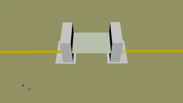
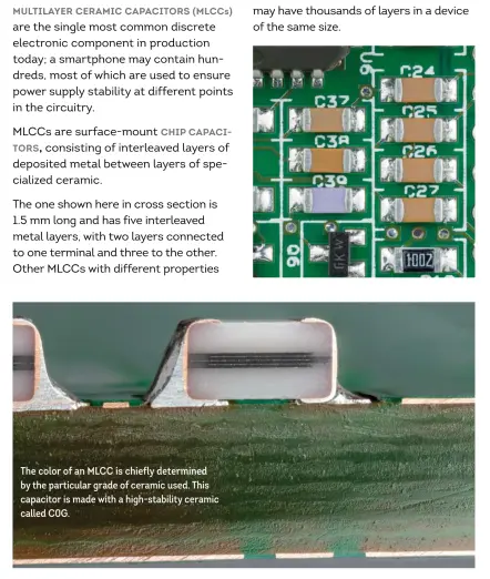
I'm doing full-wave simulation of circuit parasitics around a 100 nF surface-mount AC coupling capacitor in #openEMS. The lumped capacitance itself is modeled as a 2D plane, so its parasitic inductance is obviously almost solely controlled by its mounting height - which I had trouble determining. I had to make an educated guess that a small 100 nF capacitor requires only a few layers, so its capacitance is concentrated at the center of the Z plane. It seemed to work, but I still wanted confirmations. I remembered @tubetime@mastodon.social's book Open Circuits, and I found exactly what I needed. #electronics

3D model of the SMD capacitor for full-wave simulation.Multilayer ceramic capacitors (MLCCs)
are the single most common discrete
electronic component in production
today; a smartphone may contain hun-
dreds, most of which are used to ensure
power supply stability at different points
in the circuitry.
MLCCs are surface-mount chip capaci-
tors, consisting of interleaved layers of
deposited metal between layers of spe-
cialized ceramic.
The one shown here in cross section is
1.5 mm long and has five interleaved
metal layers, with two layers connected
to one terminal and three to the other.
Other MLCCs with different properties
may have thousands of layers in a device
of the same size.

The color of an MLCC is chiefly determined
by the particular grade of ceramic used. This
capacitor is made with a high-stability ceramic
called C0G
2025-04-24

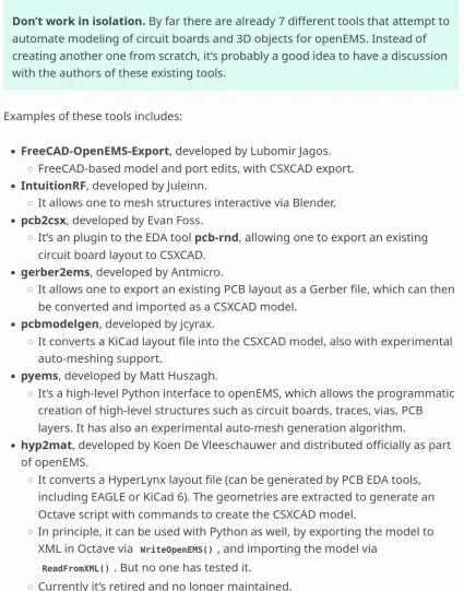
Wrote more #openEMS documentation, now playing the role of the project historian. The little-known history on the endless attempts to make simulation easier, each time with the creation, abandoning, and recreation of third-party tools. #electronics

**Don't work in isolation.** By far there are already 7 different
   tools that attempt to automate modeling of circuit boards and
   3D objects for openEMS. Instead of creating another one from
   scratch, it's probably a good idea to have a discussion with
   the authors of these existing tools.

Examples of these tools includes:

* :program:`FreeCAD-OpenEMS-Export`, developed by Lubomir Jagos.

  * FreeCAD-based model and port edits, with CSXCAD export.

* :program:`IntuitionRF`, developed by Juleinn.

  * It allows one to mesh structures interactive via Blender.

* :program:`pcb2csx`, developed by Evan Foss.

  * It's an plugin to the EDA tool :program:`pcb-rnd`,
    allowing one to export an existing circuit board layout to CSXCAD.

* :program:`gerber2ems`, developed by Antmicro.

  * It allows one to export an existing PCB layout as a Gerber file,
    which can then be converted and imported as a CSXCAD model.

* :program:`pcbmodelgen`, developed by jcyrax.

  * It converts a KiCad layout file into the CSXCAD model,
    also with experimental auto-meshing support.

* :program:`pyems`, developed by Matt Huszagh.

  * It's a high-level Python interface to openEMS, which allows
    the programmatic creation of high-level structures such as
    circuit boards, traces, vias, PCB layers. It has also an
    experimental auto-mesh generation algorithm.

* :program:`hyp2mat`, developed by Koen De Vleeschauwer and
  distributed officially as part of openEMS.

  * It converts a
2025-04-22

Wrote more documentation for #openEMS. Lumped elements pitfalls. #electronics

Lumped Element
---------------

A lumped element is an ideal resistor, capacitor or inductor with a size
assumed to be negligible. They're especially useful for modeling surface-mount
circuit components.

.. important::
   **Axis Alignment.** Lumped elements must have an orientation aligned to
   the X, Y, or Z axis. If a misaligned resistor or capacitor must be used,
   defining an distributed element based on a hypothetical material (via
   :func:`AddMaterial` with an artificial conductivity or permittivity)
   may be a workaround.

   **Parasitics**: Even though lumped elements are "ideal", their connections
   to the circuit still introduce parasitic effects (e.g., inductance from the
   overall loop area, partial inductance of terminal leads or mounting height).
   For example, an SMD capacitor’s inductance primarily comes from its mounting
   height, not internal to the capacitor itself. Full-wave simulations inherently
   capture these parasitics through the electric and magnetic fields in space.
   Thus, non-internal
   parasitics don't need to be added, such as the series inductance of an
   SMD capacitor. However, datasheets often combine internal and external-loop
   effects, making it hard to isolate the "pure" lumped element values for
   simulation - some may argue it isn't a well-defined concept to begin with.
2025-04-19

Still tweaking the #openEMS documentation. Physicists and engineers run out of variables be like... #electronics

The model is defined by the following parameters:

* ``eps_r``: Relative permittivity when frequency approaches infinity
  (:math:`\epsilon_{r,\infty}`).

* ``EpsilonDelta_n``: n-th delta dielectric permittivity, a fitted phenomenological
  term that represents relaxation strength (:math:`\Delta \epsilon_r`).

* ``EpsilonRelaxTime_n``: n-th relaxation time, inverse of the damping factor,
  a dissipative term
  (:math:`\tau_\mathrm{relax}`).

* ``Kappa``: Electric conductivity, an ohmic loss term (:math:`\kappa`).
  Not to be confused with electric permittivity, sometimes also denoted by the
  same letter.

.. warning::
   ``Kappa`` (:math:`\kappa`) always stands for electric conductivity in openEMS, 
   It's not to be confused with electric permittivity :math:`\epsilon`, which is
   sometimes also denoted as :math:`\kappa` in the literature (e.g. high-κ
   dielectric). This convention is never used in openEMS, its use in simulation
   code is strongly discouraged.
2025-04-18

More #openEMS documentation. Spent two days trying to figure out why these formulas don't match textbooks, so you don't have to. ​:cirno_hi:​ #electronics

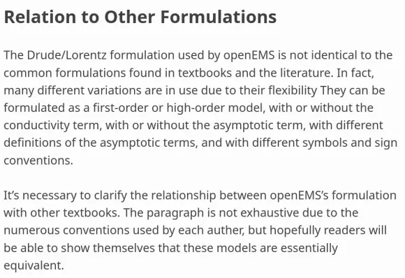
Relation to Other Formulations
""""""""""""""""""""""""""""""""

The Drude/Lorentz formulation used by openEMS is not identical
to the common formulations found in textbooks and the literature.
In fact, many different variations are in use due to their flexibility.
They can be formulated as a first-order or
high-order model, with or without the conductivity term, with or
without the asymptotic term, with different definitions of the
asymptotic terms, and with different symbols and sign conventions.

It's necessary to clarify the relationship between openEMS's
formulation with other textbooks. The paragraph is not exhaustive
due to the numerous conventions used by each auther, but hopefully
readers will be able to show themselves that these models are
essentially equivalent.
2025-04-15

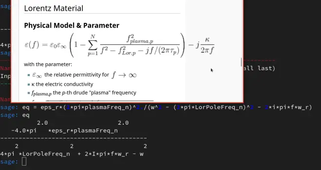
More #openEMS documentation work: I was trying to derive the equation in the project wiki using the source code, but the SageMath output doesn't make any sense... The units in the original wiki page were completely mixed up. ​:blobcatfacepalm:​ Some f in the equations are ordinary frequencies, some are angular frequencies... ​:woozy_baa:​

Comparison of the wiki formula and the SageMath output, they don't match because some "f"s are actually in angular frequency.
2025-04-15

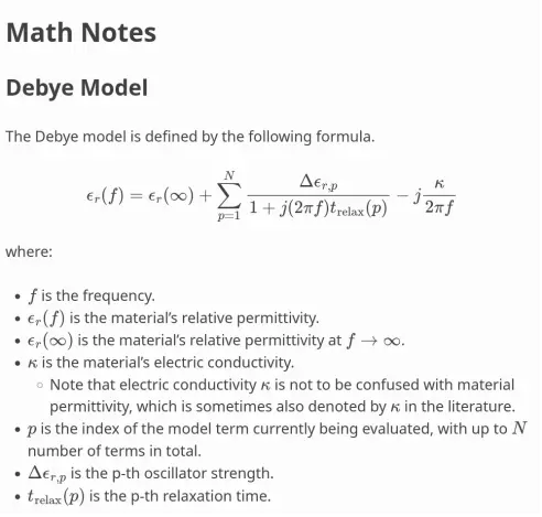
Wrote more #openEMS documentation. The math notes on the old project wiki need cleanup. The equations were written in absolute permittivity and angular frequency, while the software expects you to enter a relative permittivity and ordinary frequency, making it a cross-reference headache. ​:woozy_baa:​ I'm pretty sure the Debye formula is now correct, but I still need to check the Lorentz model. #electronics

Math Notes
==================

Debye Model
""""""""""""

The Debye model is defined by the following formula.

.. math::
   \begin{align}
   \epsilon_r(f) &= \epsilon_r(\infty) +
                   \sum^N_{p=1}{\frac{\Delta \epsilon_{r,p}}{1+ j (2 \pi f) t_\mathrm{relax}(p)}}
                   - j \frac{\kappa}{2 \pi f} \\
   \end{align}

where:

* :math:`f` is the frequency.
* :math:`\epsilon_r(f)` is the material's relative permittivity.
* :math:`\epsilon_r(\infty)` is the material's relative permittivity
  at :math:`f \to \infty`.
* :math:`\kappa` is the material's electric conductivity.

  * Note that electric conductivity :math:`\kappa` is
    not to be confused with material permittivity, which is sometimes
    also denoted by :math:`\kappa` in the literature.

* :math:`p` is the index of the model term currently being evaluated,
  with up to :math:`N` number of terms in total.
* :math:`\Delta \epsilon_{r,p}` is the p-th oscillator strength.
* :math:`t_\mathrm{relax}(p)` is the p-th relaxation time.
2025-04-15

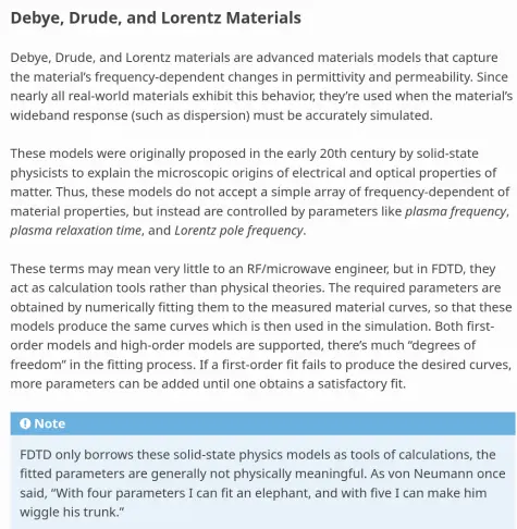
Wrote more #openEMS documentation, answering questions like: Why does Plasma Frequency have anything to do with simulating a circuit board? #electronics

Debye, Drude, and Lorentz Materials
"""""""""""""""""""""""""""""""""""

Debye, Drude, and Lorentz materials are advanced materials models that
capture the material's frequency-dependent changes in permittivity and
permeability. Since nearly all real-world materials exhibit this behavior,
they're used when the material's wideband response (such as dispersion)
must be accurately simulated.

These models were originally proposed in the early 20th century by
solid-state physicists to explain the microscopic origins of electrical
and optical properties of matter. Thus, these models do not accept a
simple array of frequency-dependent of material properties, but instead
are controlled by parameters like *plasma frequency*, *plasma relaxation
time*, and *Lorentz pole frequency*.

These terms may mean very little to an RF/microwave engineer, but in FDTD,
they act as calculation tools rather than physical theories. The required
parameters are obtained by numerically fitting them to the measured material
curves, so that these models produce the same curves which is then used in
the simulation. Both first-order models and high-order models are supported,
there's much "degrees of freedom" in the fitting process. If a first-order
fit fails to produce the desired curves, more parameters can be added until
one obtains a satisfactory fit.

.. note::
   FDTD only borrows these solid-state physics models as tools of calculations,
   the fitted parameters are generally not physically meaningful
2025-04-13

More #openEMS development: All Matlab/Octave functions now have HTML (Sphinx) documentation now. ​:patchyhyperrun_rev:​ #electronics

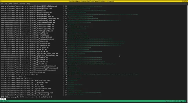
143 files changed, 4593 insertions(+), 1 deletion(-)
2025-04-10

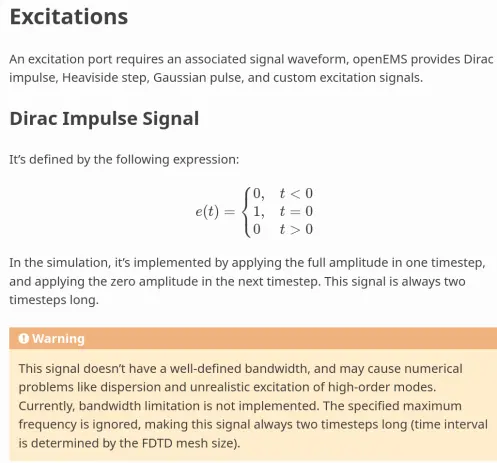
Yeah, everyone knows what a Dirac impulse is, but the devil is in the details, making documentation availability a critical problem... #openEMS #electronics

xcitations
=============

An excitation port requires an associated signal waveform, openEMS
provides Dirac impulse, Heaviside step, Gaussian pulse, and custom
excitation signals.

Dirac Impulse Signal
----------------------

It’s defined by the following expression:

.. math::

  e(t) = 
  \begin{cases}
  0, & t < 0 \\
  1, & t = 0 \\
  0  & t > 0
  \end{cases}

In the simulation, it's implemented by applying the full amplitude in one
timestep, and applying the zero amplitude in the next timestep. This signal
is always two timesteps long.

.. warning::
   This signal doesn't have a well-defined bandwidth, and may cause numerical
   problems like dispersion and unrealistic excitation of high-order modes.
   Currently, bandwidth limitation is not implemented. The specified maximum
   frequency is ignored,  making this signal always two timesteps long
   (time interval is determined by the FDTD mesh size)
2025-04-10

More #openEMS documentation. I don't think anyone else has ever reviewed such implementation details. #electronics

Excitations
=============

An excitation port requires an associated signal waveform, openEMS
provides Dirac impulse, Heaviside step, Gaussian pulse, and custom
excitation signals.

Dirac Impulse Signal
----------------------

It’s defined by the following expression:

.. math::

  e(t) = 
  \begin{cases}
  0, & t < 0 \\
  1, & t = 0 \\
  0  & t > 0
  \end{cases}

Heaviside Step Signal
-----------------------

It’s defined by the following expression:

.. math::

  e(t) = 
  \begin{cases}
  0, & t \lt 0 \\
  1  & t \ge 0 \\
  \end{cases}

Gaussian Pulse Signal
-----------------------

It's defined by the following expression:

.. math::

   e(t) = \cos{\left[2\pi f_0 \left(t-\frac{9}{2\pi f_c}\right)\right]} \cdot
          \exp{\left[-\left(\frac{2\pi f_c t}{3}-3\right)^2\right]}

where :math:`f_0` in the carrier's central frequency, :math:`f_c` is its
20 dB cutoff frequency.
2025-04-09

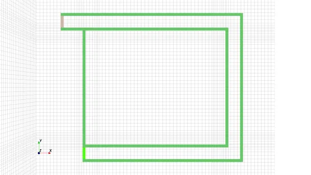
3D full-wave #openEMS simulation of the classic experiment in high-speed electronics: where does the return current go? A voltage is suddenly connected (Heaviside step) to a resistor via some wires. An incoming wire and two return wires are connected in parallel. One return path is longer, but runs with the incoming wire side by side, the other wire returns to the source via a straight path. By common sense, radio signals follow the path of least impedance, not resistance, obviously the initial rising edge mostly follows the longer path (until the currents redistribute themselves later reflections occur). #electronics
An incoming wire and two return wires are connected in parallel. One return path is longer, but runs with the incoming wire side by side, the other wire returns to the source via a straight path.

Client Info

Server: https://mastodon.social
Version: 2025.04
Repository: https://github.com/cyevgeniy/lmst