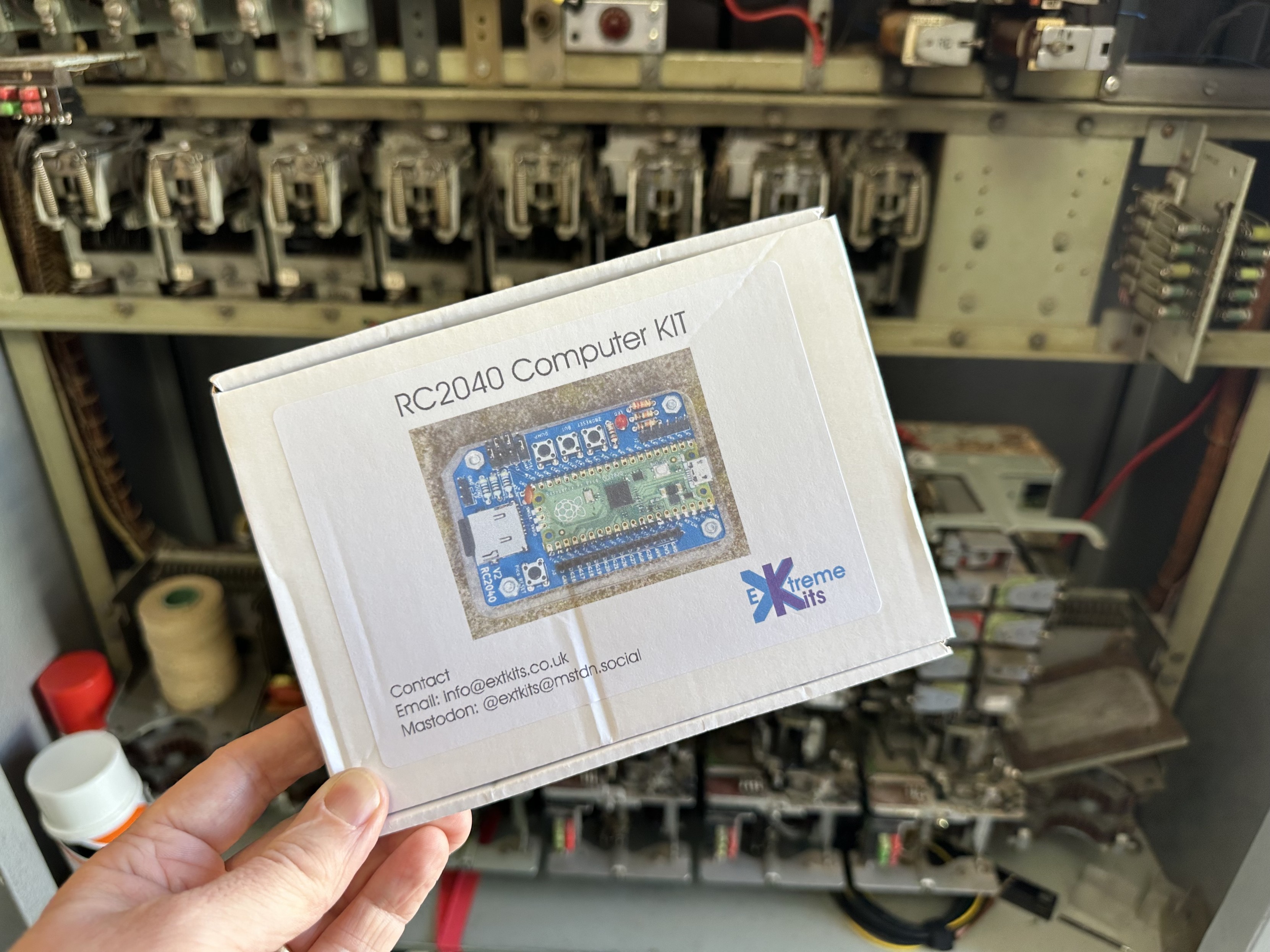
The postie has delivered my #RC2040 kit…
So I have a new project to distract me from all the other projects that are currently distracting me from the other projects that I started to switch off from work
The postie has delivered my #RC2040 kit…
So I have a new project to distract me from all the other projects that are currently distracting me from the other projects that I started to switch off from work
RC2040
I’ve recently gotten hold of a RC2014 computer and it’s great. Once I’ve gone beyond some of the basic tutorials online I might start posting something about it at some point, so watch this space.
But also, I stumbled across the RC2040 project and kit from Extreme Kits (https://extkits.co.uk/product/rc2040/). Described as a “Retro emulated Z80 CP/M computer kit” it is basically a rc2014 emulated on a Raspberry Pi Pico. So I just had to get one to have a play with that too!
It comes as a PCB, acrylic baseplate and then a pile of components – mostly resistors, buttons, jumper. The PCB itself has the surface mount footprint for the Raspberry Pi Pico – and as it is essentially emulating a RC2014, hence the name RC2040.
These are my “notes to self” to remind me what I did to get up and running as the instructions are somewhat spread around and I felt assume a bit of knowledge of the RC2014 and the Z80 ecosystem that I don’t yet have.
Main resources and references:
This post has the main usage points, which are mostly in the getting started pages, but with a few extras I had to figure out on the way too.
PCB Build Notes
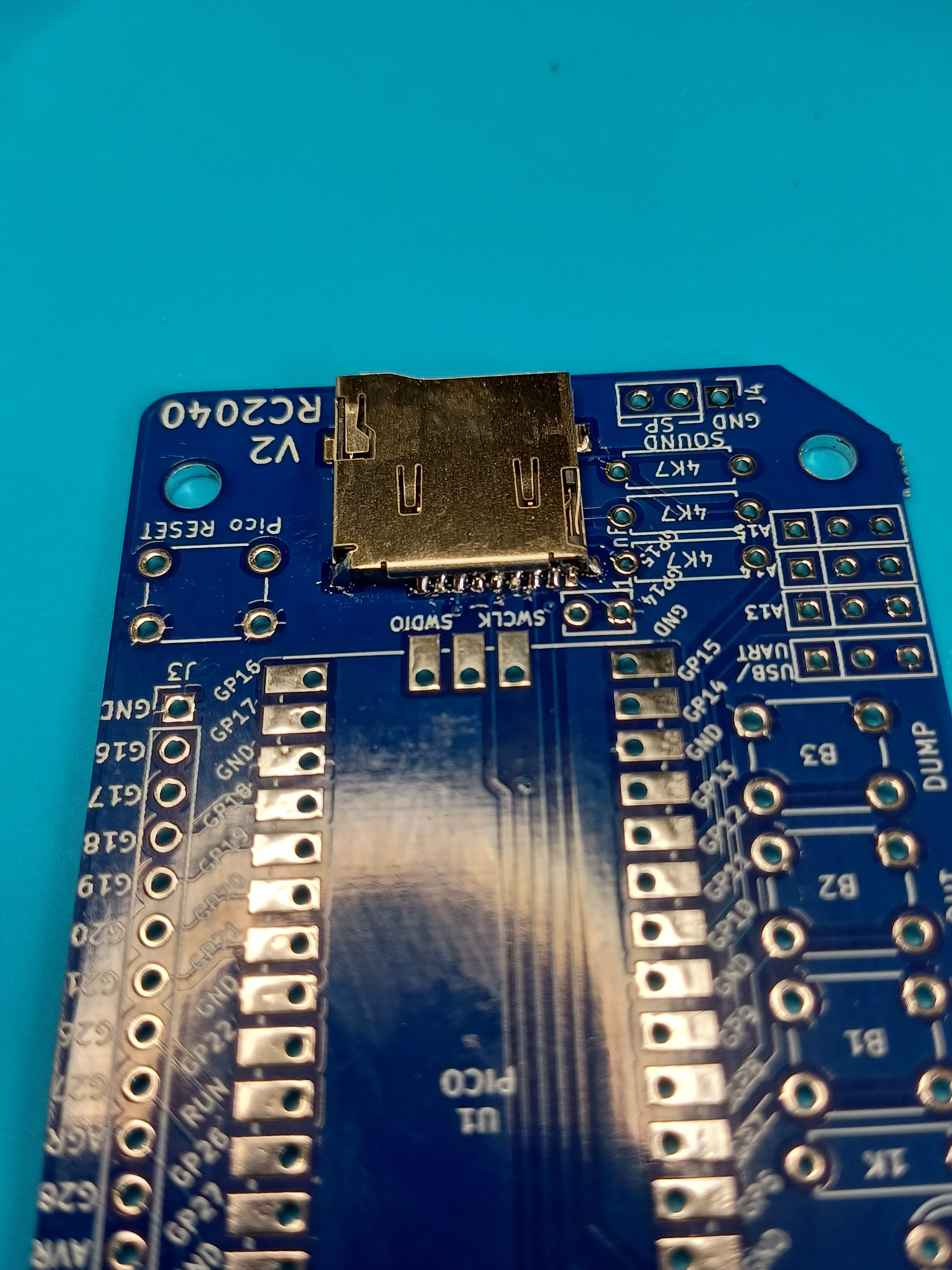
If you’re thinking about getting one of these kits, take particularly note of the warning about the micro SD card connector.
This has to be soldered on using surface mount 1mm pitch connectors and to say it is fiddly is putting it mildly! And you almost certainly won’t know if you’ve succeeded until everything else is together and you’re reading data from the card…
There is a note on the product page to ask for help prior to ordering if you want it done for you.
I just went slowly with it, fixing one of the larger grounding pads first and then using that to orient the other pins before soldering any of the others. Then it was checked thoroughly with a magnifying glass before continuing.
Other things to consider:
With hindsight, I suspect it would have been more useful for me to have had switches instead of the A13, A14, A15 jumpers and a jumper for the USB/UART setting.
Note the USB/UART switch is oriented so that USB is on the Pico side and UART (via GPIO 0/1) is at the edge of the board.
Boot Configurations
This is one area I was getting quite confused over… I think there is where knowledge of the RC2014 boot options and ROM sets would really help, but what I think is happening is as follows.
The ROM file provided is 24886009.bin. Each number represents a single bank of the ROM and consequently an address jumper setting. Following the key from here, this decodes as:
When the RC2040 is oriented with USB on the left and the address jumpers at the bottom right of the board, the order is inverted. For the A13-A14-A15 Jumper settings: “1” is the position nearest the Pico; “0” is the position nearest the edge of the board.
So, in A13-A14-A15 order the options are:
The following go into a loop for me:
As might be expected the remaining two options (101,011) do nothing.
MS Basic (000) is the same as the standard image for RC2014 that I had by default with my kit.
Booting into the SC monitor (010) works fine too. When selecting help (“?”) there are three options at the bottom to boot into BASIC, WBASIC (“warm start” BASIC) or CPM.
Booting into the CP/M monitor appears to offer some basic options (once the “press [space] to access console” message appears and space has been pressed), but apparently only the boot into CP/M will work.
It would seem that the most versatile option is to use the SC monitor (010) mode for now.
A side note on boot configuration
There are a number of places in the emulator code where a choice is made between reading configuration switches and using a configuration from the rc2040.ini file on the SD Card.
There is a hardware indication of using switches. This is determined by the setting of GP22. In the board, this is tied to GND which means “this board has switches” (i.e. address jumpers). But it is tied to GND via a (connected) solder jumper which doesn’t appear to be on the schematic. This also determines if the USB/UART jumper is present.
There is also a config setting which can determined if the switches should be overridden by what is in the config file. This is the setting [ROM]\ovjump. If this is present and set to 1 then the A13-A14-A15 values are read from the rc2040.ini file rather than the A13-A14-A15 jumper settings.
In the readme file for the SD card contents, two rc2040.ini configurations are described. The actual rc2040.ini file present is the SIO2 configuration.
Usage Notes
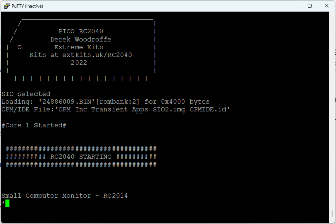
When using USB serial, the board will pause until a serial link is established. This is pretty handy as when resetting the Pico I lose the connection in PuTTY, but on “Restart Session” the session is re-established and the Pico will then boot up.
The buttons do the following:
There is a good reference for additional useful rc2040.ini file settings here: https://www.extremeelectronics.co.uk/more-rc2040-settings/
GP16,17,18,19,20,21,26,27 are broken out on an additional header and form the 8 bits of a single Z80 IO port. By default this is at PORT address 0 but that can be changed with the [PORT]\pioa rc2040.ini file option.
Serial Connection
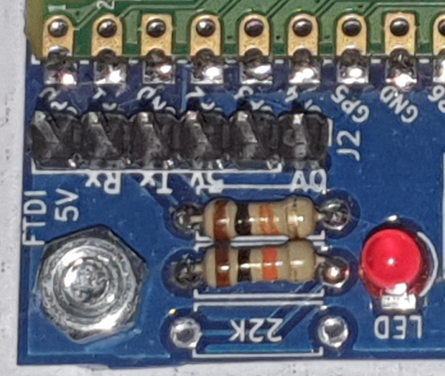
As already mentioned the RP2040 serial console can be directed over USB serial or out via UART0 on GPIO 0/1. The UART is broken out to an FDTI header on the board.
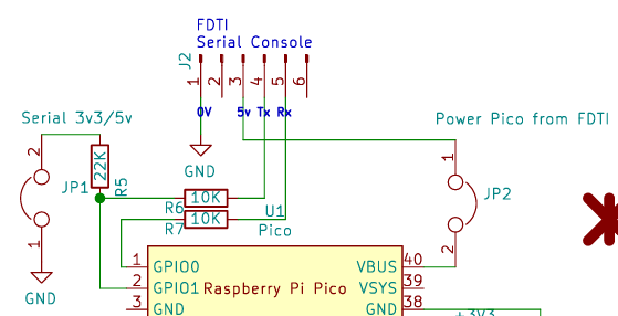
The slightly confusing thing for me is that the FTDI pins provided on the board, are labelled for the FTDI connections not the Pico’s connection. This can be seen from the schematic:
So FDTI TX is connected via an optional resistor divider to GPIO 1 which is the Pico’s RX; and FDTI RX is connected directly to the Pico’s TX.
Recall that the USB/UART jumper/switch must be in the “near the edge of the PCB” position for this to work.
Conclusion
This will do for the time being. I think I now understand how this can boot into either BASIC or CP/M, so next is to do some reading about how to get different programmes running under CP/M.
Kevin

For the ExtremeElectronics #RC2040-Users:
The actual #RunCPM v6.7 in Source & Binary
(.UF2 for RED or GREEN LED) https://github.com/guidol70/RunCPM_RPi_Pico/raw/refs/heads/main/v6_7/GL20241203_RunCPM_v6_7_RC2040.zip
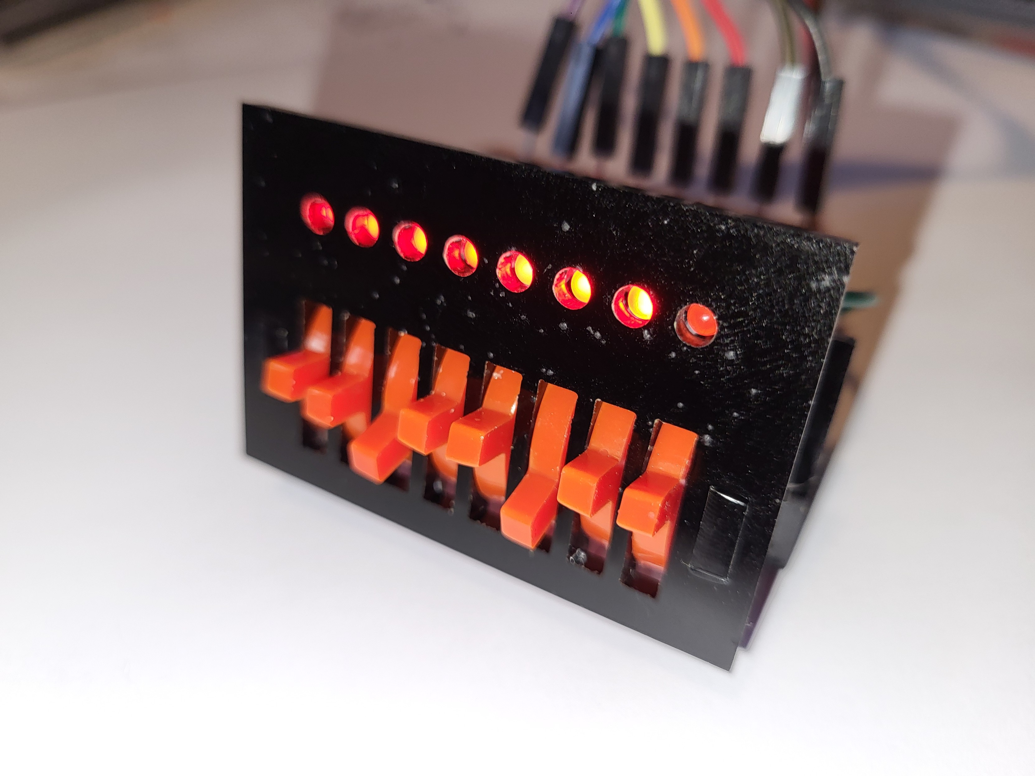
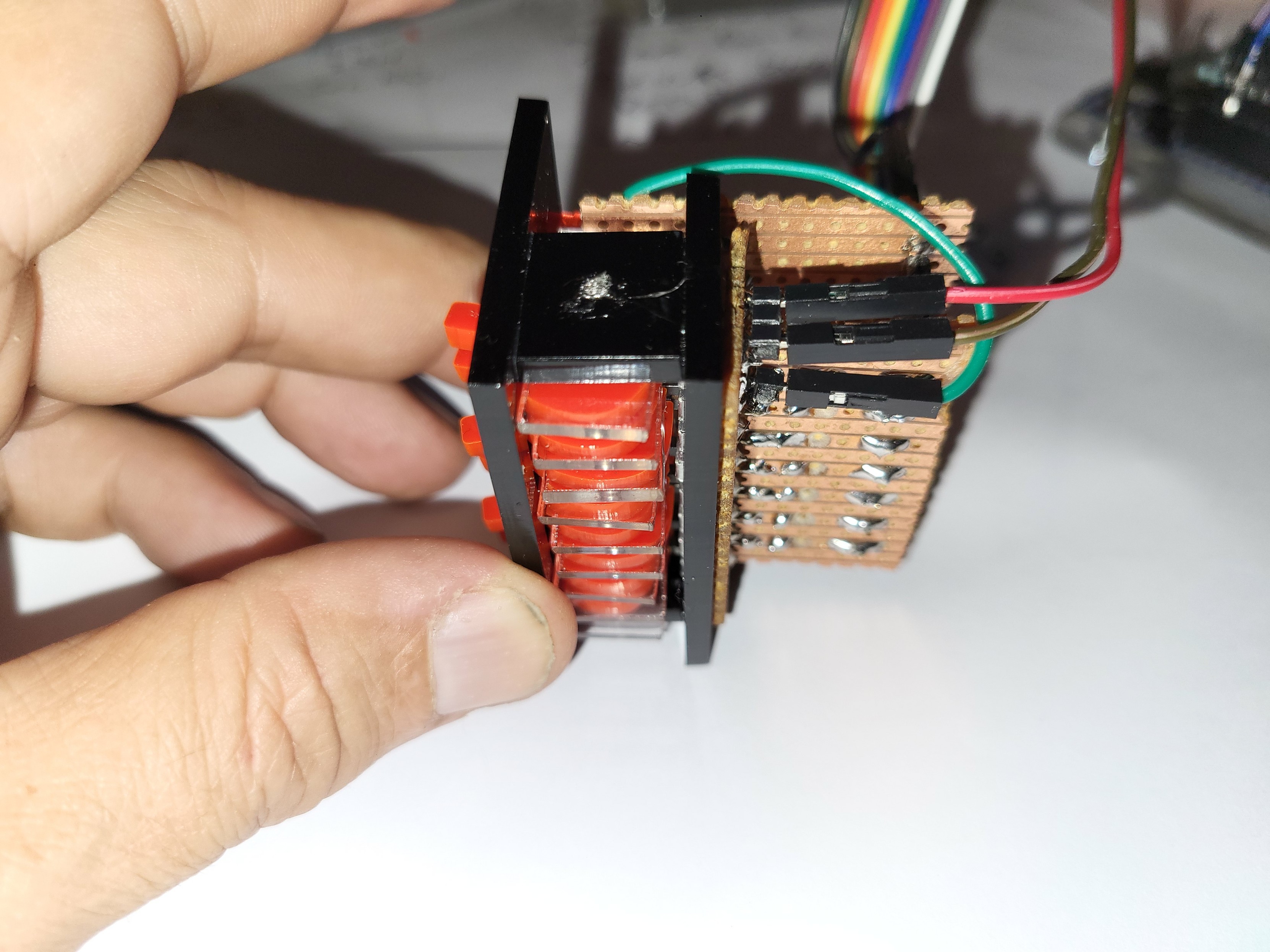
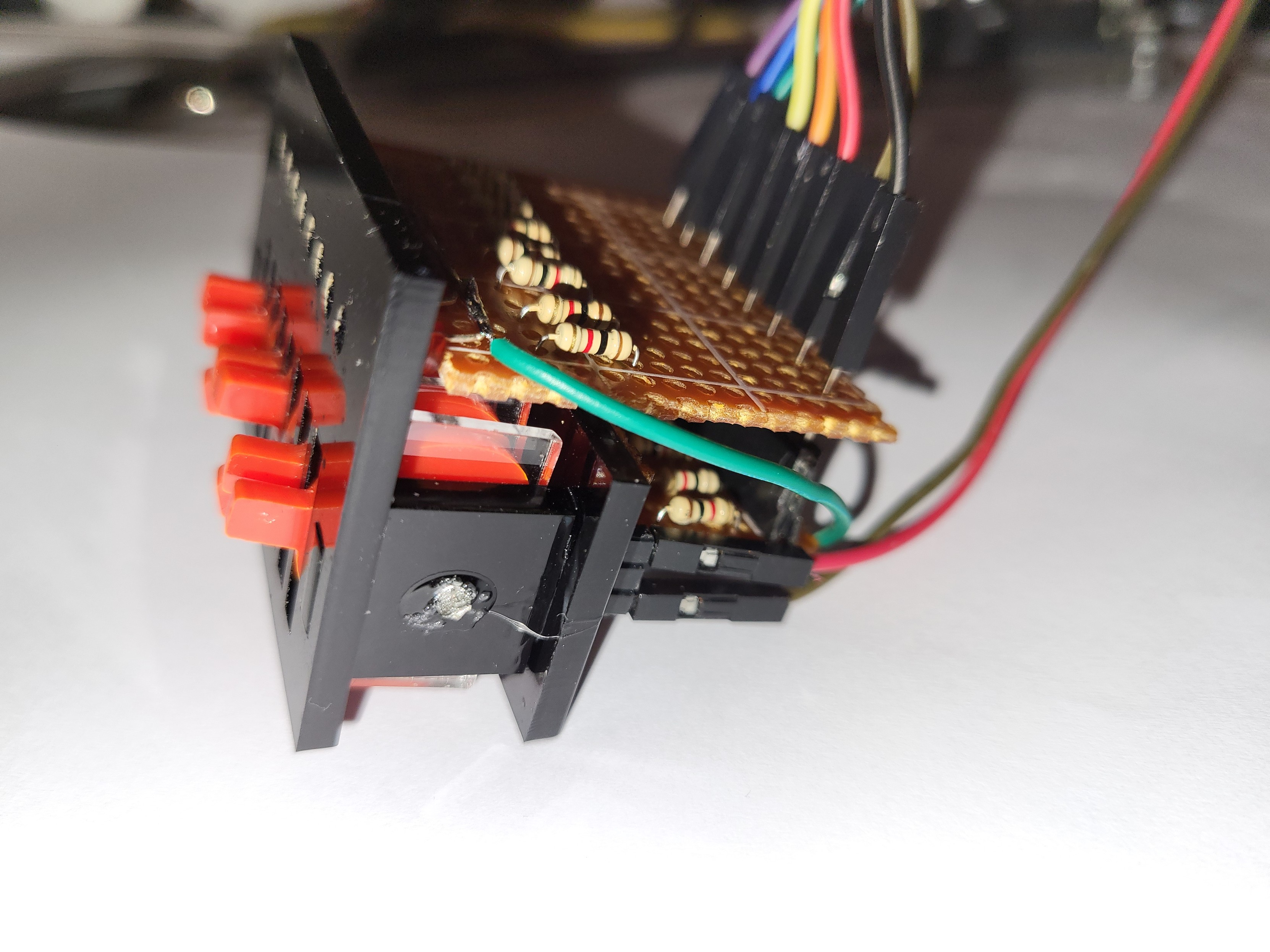
Test/development I/O port switches and leds for the @ExtKits #RC2040
This took a lot longer than it should, mostly due to vero breaking where it shouldn't and me wiring leds in every incorrect way possible.
RC2040 kit now supports ROMWBW
CPM/80 2&3 ZPM 512k of ROM disks and 160K of memory.
Plus Parallel port, SPO256AL2 speech Synth, beep, & Neo-Pixel driver. All from an Emulated Z80 on a Pi Pico.
Kit: https://extkits.co.uk/product/rc2040/
Last night I toiled well beyond my bedtime, but I got the #RC2040 source code to build me a UF2 file. I was using #VScode and the #RaspberryPi #Pico extension on Windows 10.
This was my 2nd Pico build, the 1st being the blink example 😉
Had a few challenges. Sorted out some "stuff" in the #CMake file - my first time in that jungle. Then worked through a blizzard of warnings when the first build attempt failed. Eventually I found an error hiding in that. Fixing that was enough to get me the UF2!
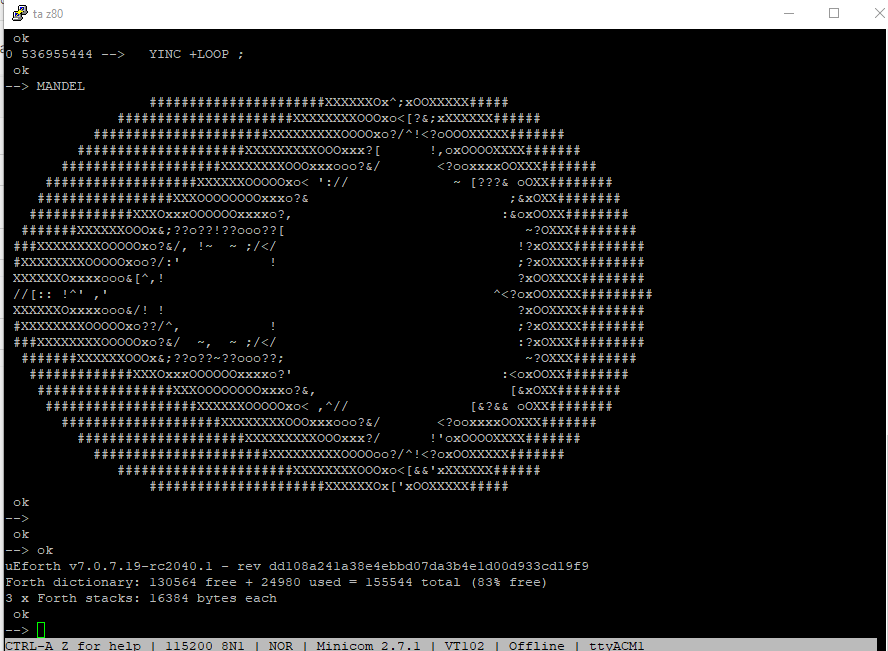
Neo-pixel and SPO256AL2 test, from an MBASIC program running on CPM/80 on ROMWBW on a Pi Pico emulating a Z80 ;)
#RunCPM #RC2040 #Pico
RED or GREEN LED usage
Update to RunCPM 6.3
.#UF2 #Binarys
https://github.com/guidol70/RunCPM_RPi_Pico/raw/main/GL20240602_RunCPM_v6_3_RC2040_Binary.zip
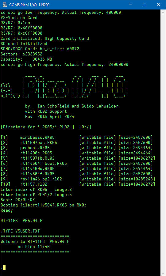
I compiled the actual #pdp11 #Pico1140 .UF2 emulator binarys for different SPI-Pinouts:
- Ian #Schofield-original
- ExtremeElectronics #RC2040 @extkits
- #RunCPM (by me)
- #RP2040 Zero (by me) https://github.com/guidol70/Pico_1140/raw/main/Binary/GL20240420_Pico_1140_Binary.zip
So, huh... The hand-soldering of the microSD port of the #RC2040 was within my ability, after all. 😅
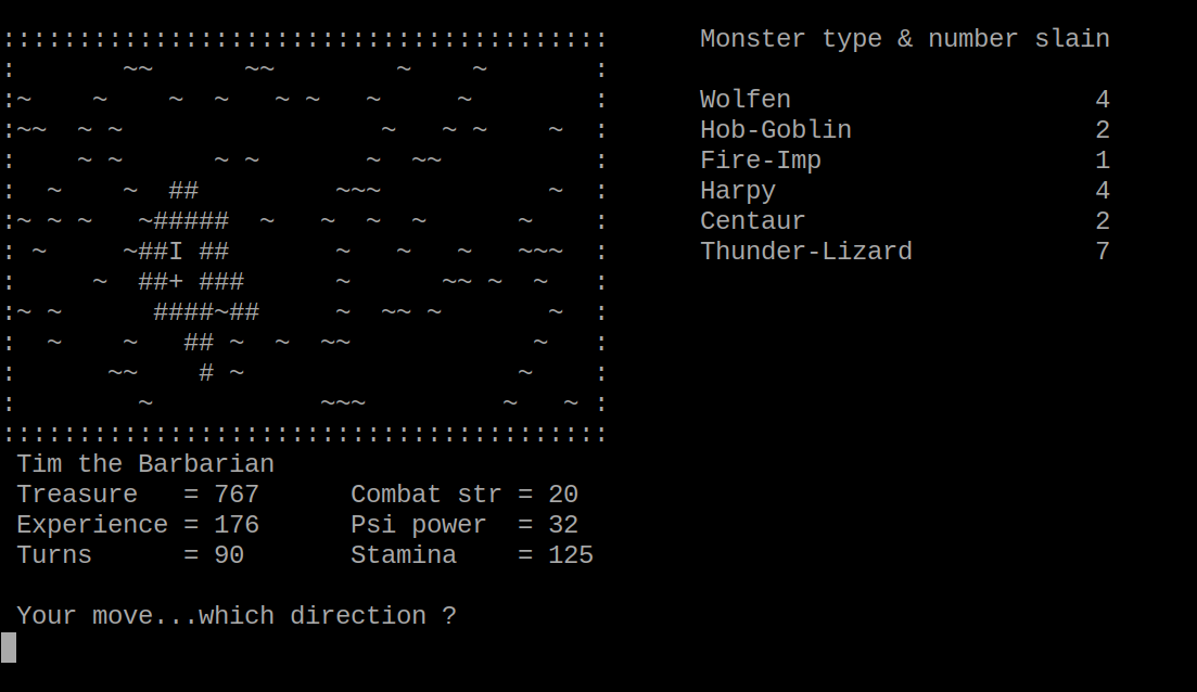
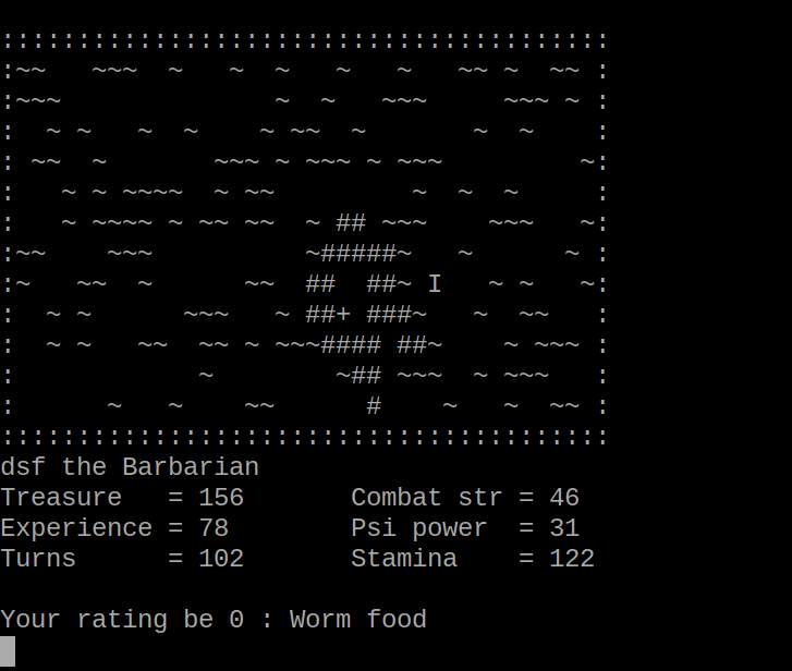
OK - I've let v1 of "The Valley" escape into the wild if anyone fancies playing a 42 year old adventure game!
Details here: https://z80.timholyoake.uk/the-valley-at-42/
If the weather stays this bad where I am, there may be a version 2 for a PicoTerm extended character set in a few days from now ...
Almost happy enough to let this version of The Valley out as a v1.
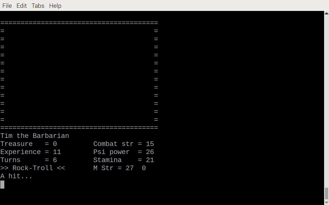
Extended data on your monster combat record is now available, as is the ability to save and retrieve current game state to/from disk.
A bit more tweaking and testing left to do. I'm then going to have a look at PicoTerm and its extended character set.
Castle scenes are now working.
There's a glitch in special finds to fix, plus yet more refactoring and speeding up scene changes required ... but the game is now playable on an #RC2014 or #RC2040.
Also on the to-do list - looking at moving beyond 7 bit ASCII codes for display when running on the PicoTerm VT emulator!
I've now reached the exalted rating of 'Peasant'

Note to self: you'd make faster progress if you don't stop to refactor the code every 10 minutes!
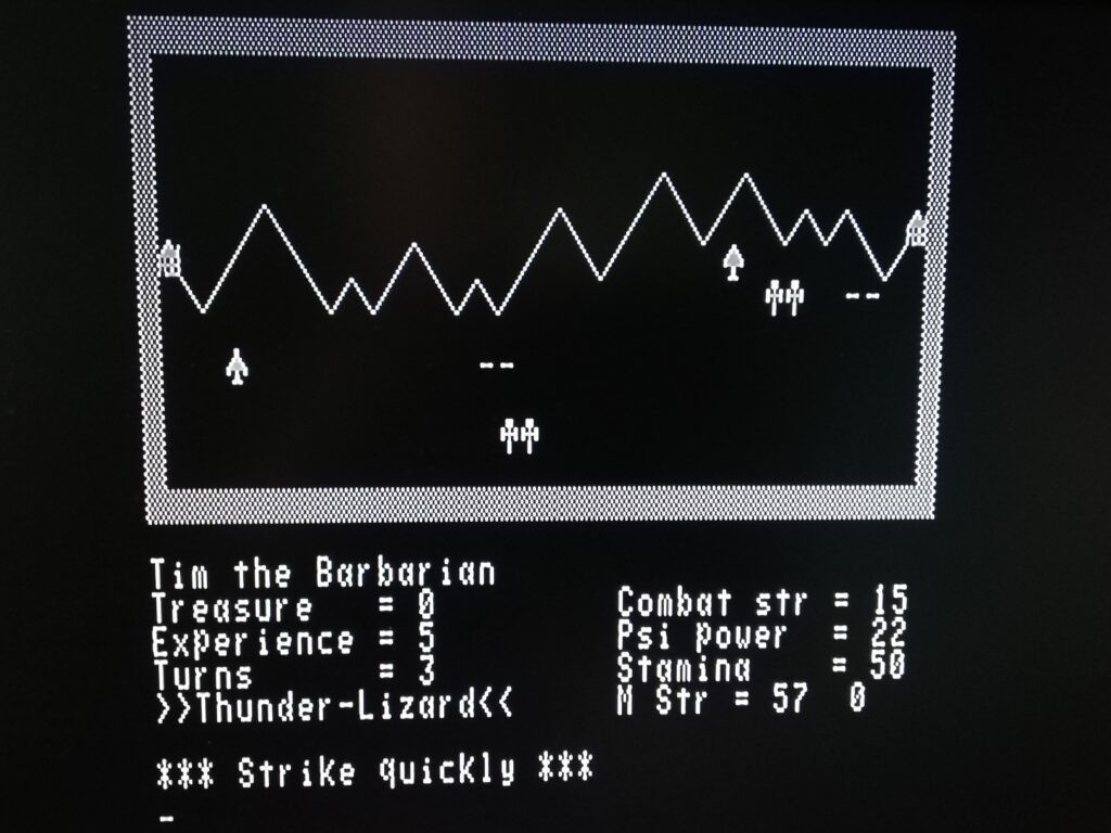
But I do have the swamp and wood scenes working correctly now. I need to work on the castles next and I've noticed glitches on scene exit and status area formatting.
And yet more refactoring is required, as well as speeding up the entry to new scenes ... this is taking longer to port than I'd estimated - nothing changes !! 😂
OK - I can now update the playing area successfully, but it's too slow to play if the whole playing area is updated every time a move is made. Time to improve the movement algorithm - should be straightforward enough I think.
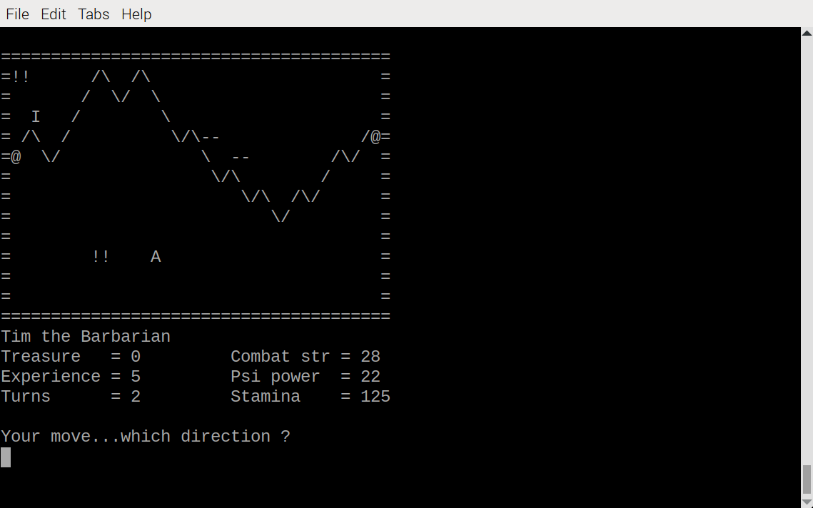
You can't see anything in the playing area yet, but movement and combat are working properly.
Making reasonable progress with this.
Amazed at how many subtle incompatibilities there are between the (pirated??) Microsoft 8K BASIC the UK101 ran and the Microsoft BASIC-80 CP/M version - eg PRINTD$ without a space between the T and the D$ is not OK in BASIC-80!
Think I've got most of these fixed now ...
So my Easter #RC2014 / #RC2040 project is getting The Valley to run under CP/M using VTxxx terminal emulation.
I'm basing it on the second (full-fat) version I wrote for the UK101 in 2022 - https://z80.timholyoake.uk/retrochallenge-2022-10/
Biggest obstacle is replacing all of the display POKES/PEEKS with suitable VTxxx escape codes and keeping track of where the player is.
I'm starting off in Microsoft BASIC, but it would be nicer to have something in Turbo Pascal eventually. Maybe!
The square root of 32 is not 4.02 - the end of the beginning
Chasing down the bugs in a #z80 emulator library.
An updated and long read for a Sunday (not quite as long as war and peace, but more fun to read).
https://z80.timholyoake.uk/the-square-root-of-32-is-not-4-02/