#arduinoProMini

Simple DIY Electronic Music Projectsdiyelectromusic.com@diyelectromusic.com
2025-05-24

USB MIDI to Serial and CV/GATE

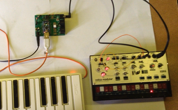
This project uses my Arduino Pro Mini MIDI USB CV PCB for a USB MIDI to Serial MIDI and CV/GATE device that has a CV/GATE that is compatible with my Korg Volca Modular.

It takes MIDI NoteOn/NoteOff and translates them into CV that can be used to set the pitch of a CV/GATE synth.

IMPORTANT: I strongly recommend that you do not connect this to your Volcas. I am not an electronics person but have accepted the risk of causing a possibly expensive problem. I will not be held responsible if you end up doing the same.

https://makertube.net/w/puRwMGeELa5zq3YhMrMC4h

https://makertube.net/w/cPjFeqigcrBHgMMPLjPNPb

Warning! I strongly recommend using old or second hand equipment for your experiments.  I am not responsible for any damage to expensive instruments!

If you are new to Arduino, see the Getting Started pages.

The Circuit

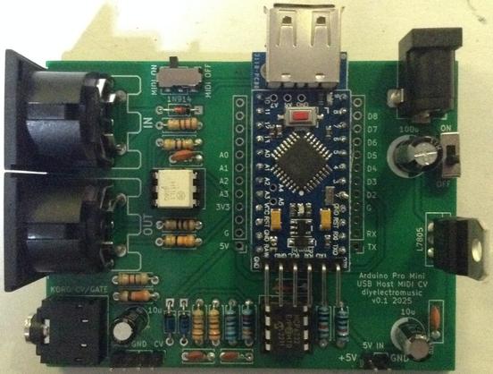
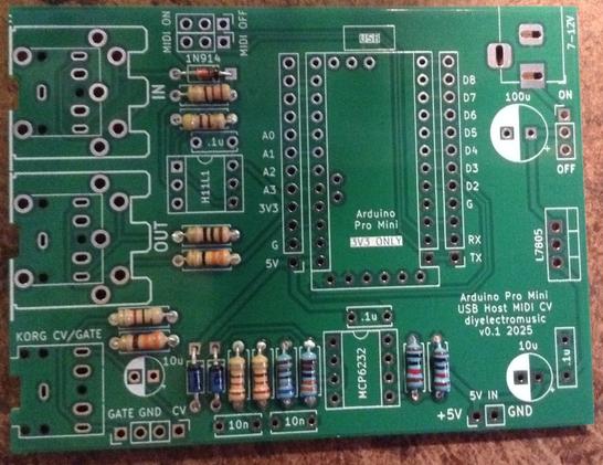
This is an application for my completed Arduino Pro Mini MIDI USB CV PCB.

The Code

The board was designed to require a PWM output on D3. With hindsight, D9 might have been more useful as D9 is a “Timer 1” timer on the ATMega328, but D3 is a “Timer 2” timer. The former are 16-bit timer/counters. The latter are only 8-bit.

No matter. I still have 255 levels of PWM to play with.

The initial PWM criteria I wanted were:

  • No prescalar – run at full CPU speed. In the case of a 3V3 Pro Mini this is 8MHz.
  • Use FastPWM mode – this will count up and then reset to zero.
  • Use a TOP value of 255 – the maximum.
  • Use the OC2B output, which is connected to D3. OC2A is not used.
  • Use the mode where OC2B is cleared on compare match; set at 0 (BOTTOM).
  • The PWM value is therefore written into OCR2B.

At some point the code will have to translate from MIDI note number over to a PWM value. My previous project mapped MIDI note C2 (36) onto 0V and went up from there for 5 octaves to C7 (96). This is a range of 60 steps, so actually, revisiting the PWM code, if we change the mode to use an alternative TOP Value of 239, that means each MIDI note corresponds to a specific step of 4. That would be pretty useful!

So the updated PWM criteria is now as follows:

  • No prescalar – still run at full CPU speed. In the case of a 3V3 Pro Mini this is 8MHz.
  • Use FastPWM mode – this will count up and then reset to zero.
  • Use a TOP value of OCR2A, which will be set to 239.
  • Use the OC2B output, which is connected to D3. OC2A is not used.
  • Use the mode where OC2B is cleared on compare match; set at 0 (BOTTOM).
  • The PWM value is therefore written into OCR2B.

The PWM operating frequency is given by a formula in the datasheet, but is basically the time it takes for the counter to count from 0 to 239 and reset, whilst running at 8MHZ. So the PWM frequency = 8000000 / 240 = 33.3kHz.

At such a frequency the (now updated) PWM filter components chosen give a pretty smooth output between 0V and 3.3V, which are them amplified using the OpAmp for a 0V to 5V range.

Note: No interrupts are required for the operating of PWM in this manner. We can just update the PWM value whenever is useful during the operation of the code.

The complete PWM code is thus as follows

void initPwm() {
pinMode(3, OUTPUT);
TCCR2A = _BV(COM2B1) | _BV(WGM21) | _BV(WGM20);
TCCR2B = _BV(WGM22) | _BV(CS20);
OCR2A = 239;
}

void setPwm (uint8_t pwmval) {
OCR2B = pwmval;
}

The value used for PWM will only be active for 0-239. Any value of 240 or higher will just be considered “always on”.

This all means that converting from MIDI to PWM value is now pretty trivial:

#define MIDI_LOWEST_NOTE  36 // C2
#define MIDI_HIGHEST_NOTE 95 // C7
uint8_t midi2pwm (uint8_t note) {
if (note < MIDI_LOWEST_NOTE) note = MIDI_LOWEST_NOTE;
if (note > MIDI_HIGHEST_NOTE) note = MIDI_HIGHEST_NOTE;
return (note - MIDI_LOWEST_NOTE) * 4;
}

Logging the average voltage for each MIDI note (pre and post amplification) gives me the following:

C20.080.08C30.721.06C41.352.03C52.023.01C62.653.95C73.284.90

Plotting these on a graph looks like this:

That is a pretty good linear response, but is slightly under in terms of the top-end output. At 1V/oct a semitone is around 83mV, so dropping 0.1V at the top ought to be dropping a semitone.

But jumping through the octaves it sounds all right to me. It’s definitely not dropping a semitone anyway, so I’m not sure what is going on. I might need to come back to this one!

The rest of the code is fairly straightforward MIDI reception and processing that I’ve done several times before now. There are a few design notes:

  • Automatic MIDI THRU is turned off or both serial and USB MIDI.
  • When a note that is not on the required channel or is out of the C2-C7 range is received, it is ignored.
  • Anything received over USB is automatically sent to the serial OUT and anything received over serial is automatically sent to the USB OUT.
  • NoteOff is only processed if received for the currently playing note.
  • Consecutive NoteOn messages update the CV and replace the previously playing note.
  • There is an option for a GATE type operation:
    • GATE goes HIGH on NoteOn.
    • GATE goes LOW on NoteOff.
  • Or for a TRIGGER pulse type operation:
    • GATE goes HIGH on NoteOn.
    • GATE remains HIGH for a defined time (e.g. 10mS) then automatically goes off.
  • On reception of NoteOff there are several possible options for what to do with the CV:
    • Leave it and do nothing. This allows any envelopes to complete on removal of the GATE signal with no change of CV. But the CV will remain at the last level until a new note is received.
    • Set it to the NoteOff pitch received. Although in reality this is probably going to be the same as “do nothing”.
    • Set the CV to 0. This means there is no “dangling” CV voltage, but the synth will probably respond to the changing CV.
  • I’ve left in a compile-time PWMTEST mode that just plays the different Cs for measuring voltages, and so on.

Find it on GitHub here.

Closing Thoughts

This actually seems to work surprisingly well. I did wonder if the apparent inaccuracies of the output might cause an issue, but it doesn’t seem to.

The PWM filter issue was annoying, but on the one hand, it was a lot easier to build and debug with a PCB in hand; but of course on the other hand, if I’d done it first on solderless breadboard, the problem would have almost certainly be spotted and the design would probably have been right.

This has only looked at a pitch CV. It would be interesting at some point to do some kind of MIDI CC to CV control device.

Kevin

#arduinoProMini #cv #define #korg #midi #midi2cv #usbMidi #volca

Simple DIY Electronic Music Projectsdiyelectromusic.com@diyelectromusic.com
2025-05-23

Arduino Pro Mini MIDI USB CV PCB Build Guide

Here are the build notes for my Arduino Pro Mini MIDI USB CV PCB Design.

Warning! I strongly recommend using old or second hand equipment for your experiments.  I am not responsible for any damage to expensive instruments!

If you are new to electronics and microcontrollers, see the Getting Started pages.

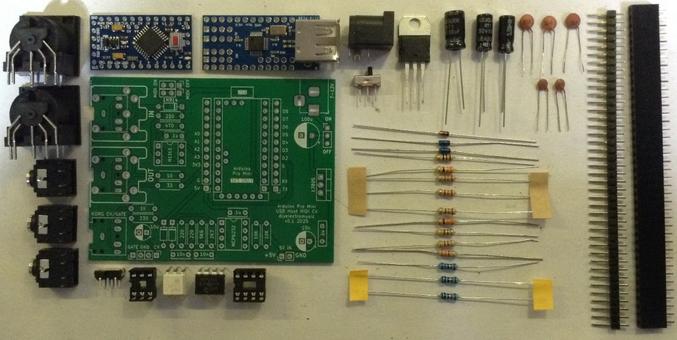
Bill of Materials

  • Arduino Pro Mini USB MIDI Host CV PCB (GitHub link below)
  • Arduino Pro Mini (3V3/8MHz version)
  • Mini USB Host Shield 2.0
  • 1x H11L1
  • 1x MCP6232
  • Diodes: 1x 1N4148 or 1N914 signal diode; 2x BAT43 Schottky
  • Resistors: 10Ω, 33Ω, 1x 220Ω, 330Ω, 470Ω, 3x 1K, 2K7, 5K6, 2x 10K (*)
  • Ceramic Capacitors: 4x 100nF (*)
  • 1x 3.5mm stereo TRS
  • Either 2x 3.5mm stereo TRS OR 2x 5-pin, 180 degree MIDI DIN sockets
  • Pin headers
  • Optional: 2x 12-way pin header sockets
  • Optional: 1x 6-way DIP socket; 1x 8-way DIP socket

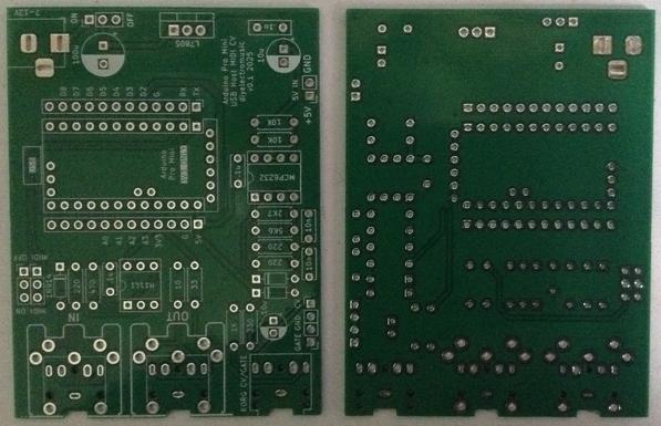
* The PCB shows the use of 2x 10nF and 2x 200Ω resistors for the PWM filter part, but 100nF and 1K work much better.

Optional: Power circuit

  • 7805 regulator
  • Electrolytic Capacitors: 1x 10uF, 1x100uF
  • Ceramic Capacitors: 1x 100nF
  • 1x SPST power switch 2.54mm pitch

Build Steps

Taking a typical “low to high” soldering approach, this is the suggested order of assembly:

  • Diodes
  • Resistors
  • DIP sockets (if used) and TRS sockets (if used).
  • Disc capacitors.
  • Switches (if used).
  • Jumper headers.
  • Electrolytic capacitors (if used).
  • DIN sockets (if used).
  • 7805 (if used).
  • Arduino + USB Host Shield (see notes below).

The Arduino Pro Mini and USB Host Shield need to be soldered together as a unit. If using header sockets, these will require longer header pins and will need soldering together as a single unit “off board”.

If not using sockets, normal pin-headers should suffice, in which case it is probably easier to solder the pin headers to the PCB and then add the USB Host shield, followed by the Pro Mini.

The USB Host shield requires a track cutting and a connection made from the Arduino’s VIN to the shields VBUS pad. See photos and discussion in the text.

Note: the PCB incorporates a capacitor on the CV PWM output to the TRS socket. This would be required if this was an audio signal to remove the DC bias. But as this is a CV output, the capacitor should be replaced with a simple wire link. More on that below.

Here are some build photos.

The two 220Ω resistors should be replaced with 1K instead.

If using MIDI TRS sockets, these should be added, along with the CV/Gate socket, next with the (optional) DIP sockets.

I’m going to use MIDI DIN sockets, so they will be left almost to last.

The MIDI on/off is required to disabled MIDI to allow sketch uploading to the Pro Mini. This can be replaced with 2×3 pin headers and jumpers, or if the Pro Mini will be removed for programming, even wire links.

I’m using a DPDT slider switch with a 2×3 2.54mm pitch.

The two 10nF capacitors should be replaced with 100nF capacitors instead.

If using 2x 12-way header sockets for the Arduino, these can be added at the same time as other pin headers next.

I’m planning on soldering my USB Host shield and Pro Mini directly to the board, so the best way to do that seems to be to add the headers to the board, as shown below, then I’ll add the shield and Pro Mini later.

The power circuitry is optional. This allows a 7-12V DC barrel jack (centre positive) to be used to create the required 5V for the Pro Mini and USB.

Alternatively, there is a 5V/GND direct jumper header that may be used instead. This should not be used to power the board if the regulator is fitted, but can be used as a 5V source if required.

Note: as already mentioned, when adding the electrolytic capacitors, the 10uF next to the CV TRS socket should be left out and replaced by a wire link.

The full photo below shows the capacitor present – I had to remove it!

The MIDI DIN sockets, if used, are the last component apart from the Arduino itself.

I will be stacking the USB shield and Pro Mini, so the shield goes on next. Note: there is a track that requires cutting between the VBUS solder pad and the 2K2 resistor as shown below. Note, this track must not be cut between the USB socket and the VBUS pad…

Cutting this track removes the connection between the USB VBUS lines and VCC on the PCB, which is running at 3V3. Once cut, a wire can then be soldered between the VBUS pad and the pin that will eventually connect to the Pro Mini’s VIN pin as shown below.

At this point the Pro Mini can now be added on top. I’ve not used any additional spacers, simply relying on the existing solder on the pin headers (from the USB shield) and the presence of the patch wire to distance the board enough. The pin headers themselves weren’t long enough, for me, to add proper plastic spacers, so I didn’t.

Testing

I recommend performing the general tests described here: PCBs.

The sample application section below lists some sketches that will test the various functions of the board.

An oscilloscope can be used to check the voltage output from the PWM signal.

PCB Errata

There are the following issues with this PCB:

  • As already mentioned, there are two issues with the CV output circuit:
    • The electrolytic capacitor should be replaced with a wire link.
    • The 10nF and 220Ω resistors in the filter should be replaced with 100nF and 1K.

Enhancements:

  •  The CV and GATE signals are different levels at present. CV is 0-5V; GATE is 0-3.3V. Perhaps they ought both be 5V signals.

Find it on GitHub here.

Sample Applications

The following GPIO pins are used with this PCB:

D0/D1RX/TX for Serial MIDID2GATE outputD3PWM CV outputD9INT pin for USB Host shieldD10-D13SPI link to USB Host shield

Here are some applications to get started with.

Note: I found that serial MIDI would not work when powered via the programming header, presumably because my programmer was controlling RX/TX. To test MIDI the board had to be powered via the barrel jack or 5V directly.

Also recall that MIDI needs to be OFF in order to upload sketches.

For the last two, some minor code changes are required.

For toneMelody, the pin used need changing from pin 8 to pin 2 in the tone() and noTone() calls.

For the PWM output, the following configuration options must be set:

//#define FREQPOT A0
//#define PIN_9_PWM_OUTPUT 1 // Uses Timer 1
#define PIN_3_PWM_OUTPUT 1 // Uses Timer 2

In both the GATE and PWM test, it is actually possible to hook up a speaker via a stereo 3.5mm jack to the CV/GATE TRS socket.

WARNING: If you do this, the speaker will be receiving a 0-5V signal on either the L or R outputs (depending on the test). This is a lot more than a line input signal (which is typically +/- 0.8V) so do not hook this up to standard audio input.

Alternatively, just check the signals via the GATE/CV jumper header with an oscilloscope.

The PWM output should be 0-5V. The GATE output should be 0-3.3V.

Use as a USB to CV/GATE Converter

The CV/GATE TRS output follows the standard set for the Korg Volca Modular (see Korg Volca Notes).

I show how to use this as a USB MIDI interface for a CV/GATE synth here: USB MIDI to Serial and CV/GATE.

IMPORTANT: Do not use this board with your Korg Volcas unless you know what you are doing, are able to validate all signals prior to connection yourself, and happy with the very real possibility that the board might do something that damages the Volca.

I am not an electronics person and will not be responsible for damage to expensive or treasured equipment. I only use cheap or disposable equipment in my own projects.

Closing Thoughts

Adding that capacitor was a case of me running on “autopilot” I think, but that is a straightforward fix, so no real harm done.

At the end of the day, this whole board is a little niche, even by my standards.

But it seems to work well enough that I can get on with writing some proper firmware for it now.

Kevin

#arduinoProMini #cv #korg #midi #pcb #pwm #usbHost #usbHostMidi #volca

Simple DIY Electronic Music Projectsdiyelectromusic.com@diyelectromusic.com
2025-05-23

Arduino Pro Mini MIDI USB CV PCB Design

This is essentially a version of my Korg Volca Modular MIDI to CV PCB Design merged with my Arduino Pro Mini MIDI USB HOST PCB Design to give me USB MIDI to serial MIDI and CV.

Warning! I strongly recommend using old or second hand equipment for your experiments.  I am not responsible for any damage to expensive instruments!

If you are new to electronics and microcontrollers, see the Getting Started pages.

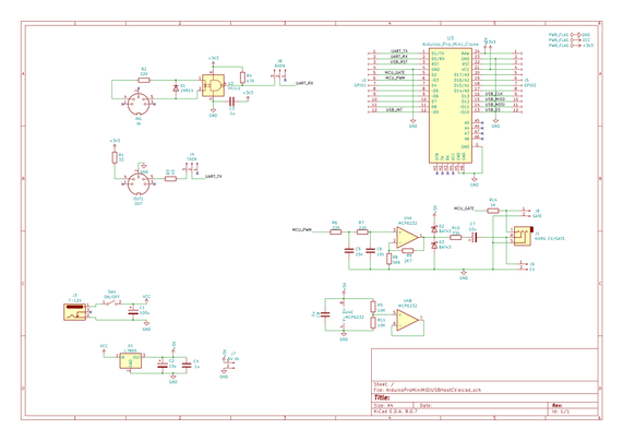
The Circuit

As previously mentioned this is largely a merging of two existing designs. The main elements are:

  • Arduino Pro Mini (3V3/8MHz) with optional USB Host Shield already attached.
  • 3V3 compatible Serial MIDI IN/OUT circuit.
  • 5V power circuit via a 7805 regulator feeding the VIN of the Pro Mini.
  • PWM output filter.
  • 3V3 to 5V opamp amplifier stage (largely based on HAGIWO’s designs).
  • Korg Volca compatible Gate/CV out via a TRS socket.

I’m using a MCP6232 rail-to-rail dual OpAmp, but I’m only using one of them, so apparently good practice dictates normalising the input of the unused OpAmp to ideally the mid-voltage of the power rails, which I’ve done using two resistors as a potential divider.

The OpAmp is set up for a noninverting amplifier aiming for, as I understand things, a gain of 5/3.3 or ~1.51 as follows:

  • Non-Inv Gain = 1 + R(feedback) / R(toground) = 1 + 2K9 / 5K6 = 1.51

Note: the capacitor in the PWM output circuit is actually an error. It isn’t required for a CV output.

Also, the CV output is amplified to make it a 0-5V signal, but the GATE output remains a 0-3.3V signal.

A note on the PWM Filter.

The circuit was originally pasted on from somewhere else and I have to confess I didn’t think about the differing nature of a PWM circuit for a control voltage compared to audio.

As such, the stated component values of 220Ω and 10nF, with a cut-off frequency of upwards of 70kHz whilst useful for audio, are pretty useless for a CV. In the actual build, I’ve used values of 1K and 100nF which gives a cutoff frequency of around 1.5kHz.

That will teach me to properly think about my requirement before cutting and pasting in one of my previous circuits 🙂

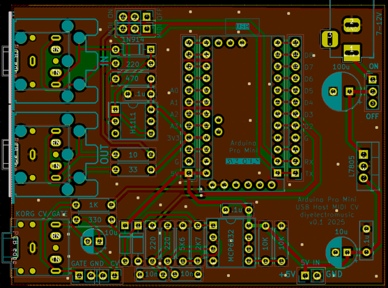
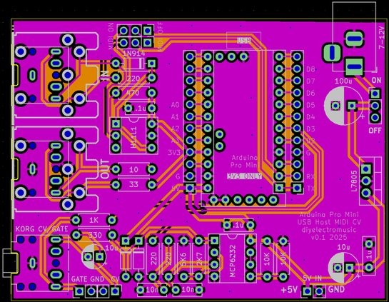
PCB Design

Unlike my last design this one assumes the USB host shield will be fixed to the Pro Mini, keeping the footprint as small as possible.

I’ve allowed for both MIDI DIN and TRS sockets. There is also an option for individual GATE and CV out via jumper headers in addition to the Korg Volca compatible TRS.

I’ve included a MIDI switch with the footprint of a 2×3 set of 2.54mm headers so that could be jumpers or a switch as required. If the Pro Mini is socketed (which isn’t so easy if a USB Host shield is attached, but would be possible with longer pin headers), then the MIDI switch could be omitted. It is only there to disconnect MIDI from the Pro Mini UART when uploading sketches.

There is a bit of space around the 7805 in case a small heatsink is required. There is also the option to power the board directly from a 5V supply via a two-pin jumper header.

The Pro Mini footprint includes the programing header, but this isn’t used on the board and should probably be ignored.

Closing Thoughts

My previous MIDI to CV was code for an ATtiny85, so I’ll need to rewrite the code for the ATMega328 on the Pro Mini to support the USB to Serial MIDI routing in addition to CV and GATE.

Kevin

#arduinoProMini #cv #korg #midi2cv #pcb #usbHost #volca

Simple DIY Electronic Music Projectsdiyelectromusic.com@diyelectromusic.com
2025-05-23

Arduino Pro Mini USB Host Proto PCB Build Guide

Here are the build notes for my Arduino Pro Mini USB Host Proto PCB.

Warning! I strongly recommend using old or second hand equipment for your experiments.  I am not responsible for any damage to expensive instruments!

If you are new to electronics and microcontrollers, see the Getting Started pages.

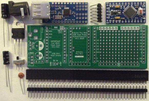
Bill of Materials

  • Arduino Pro Mini USB Proto PCB (GitHub link below)
  • Arduino Pro Mini (3V3 version)
  • Mini USB Host Shield 2.0
  • 2x (or 4x) 12-way pin header sockets
  • Pin headers

Power supply (optional):

  • 1x 7805 regulator
  • 1x 2.1mm barrel jack socket (see photos and PCB for footprint)
  • 1x 100nF ceramic capacitor
  • 1x 10uF electrolytic capacitor
  • 1x 100uF electrolytic capacitor
  • Optional: 1x slider switch, PCB mount, 2.54mm pitch connectors

The power supply section can be omitted if the board is to be powered directly off 5V, for which an additional 5V/GND set of pin headers is provided.

Build Steps

There isn’t a particular assembly order for this board, but I built it in the following order:

  • Prepare the mini USB Host shield (see below).
  • Header pins for the mini USB Host shield.
  • Header sockets for the Pro Mini.
  • Components for the power supply.

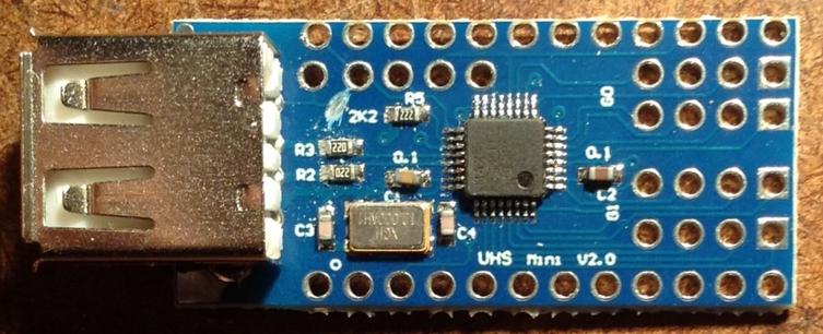
The Mini USB Host shield will probably require a track cutting to isolate VBUS from the 3V3 supply of the Pro Mini. The track in question links the VBUS solder pad to the nearby 2K2 resistor. The track needs to be cut between the pad and the resistor, but care is needed to ensure it isn’t cut on the “USB” side. See photo below.

Here are some build photos.

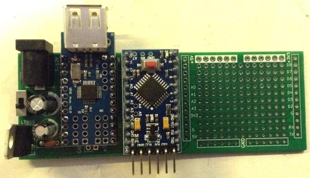
Notice in the above there is an additional single pin for the VBUS connection. I’ve used pin headers rather than a socket to allow me to mount the USB Host shield permanently on the board.

If a socket is used then it will be necessary to find an alternative means to connect the VBUS pad on the shield to the VBUS or 5V connection on the PCB.

I’m not using any headers for the Pro Mini’s programming connection. This doesn’t actually do anything on the PCB and is really just there for helping to orient the board.

In the following, I’ve only actually soldered the pins on the USB Host shield that are used to connect it to the Pro Mini. There are 9 in total, not including VBUS, and all, apart from a second GND, are labelled on the PCB:

  • Top four pins on the left (SS, MOSI, MISO, CLK).
  • Topmost single pin on the right (IN).
  • GND and 3V3 on the left (2nd and 4th from the bottom).
  • GND and RST on the right (3rd and 4th from the bottom).

If used, I soldered the power supply components last.

Testing

I recommend performing the general tests described here: PCBs.

Note: when programming the Pro Mini an additional programming header is required.

Some of the cheap programmers do not accurately set the voltage for powering the board, even if there is a switch for 5V/3V3 operation, so it is worth double checking prior to use.

If an external 5V connection is required, the additional GND/5V header pin at the bottom of the USB Host shield can be used.

PCB Errata

There are the following issues with this PCB:

  •  None at this time.

Enhancements:

  • I’ve included a footprint for the programming header, but it doesn’t do anything or go anywhere. 

Find it on GitHub here.

Sample Applications

Here is a simple USB MIDI monitor application that can be used to see if the board is working:

Closing Thoughts

As I say, I’m not sure this will get a lot of use, but it can go in the bits box for a rainy day!

Kevin

#arduinoProMini #pcb #usbHost

Simple DIY Electronic Music Projectsdiyelectromusic.com@diyelectromusic.com
2025-05-23

Arduino Pro Mini USB Host Proto PCB Design

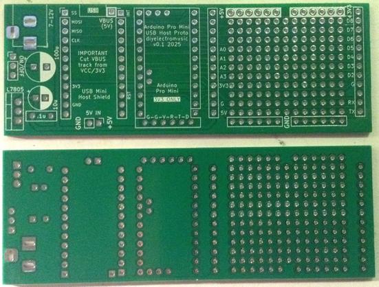
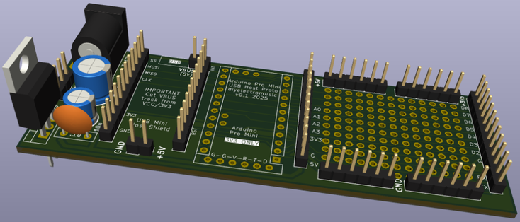
This is a prototyping board for an Arduino Pro Mini and mini USB Host shield.

Warning! I strongly recommend using old or second hand equipment for your experiments.  I am not responsible for any damage to expensive instruments!

If you are new to electronics and microcontrollers, see the Getting Started pages.

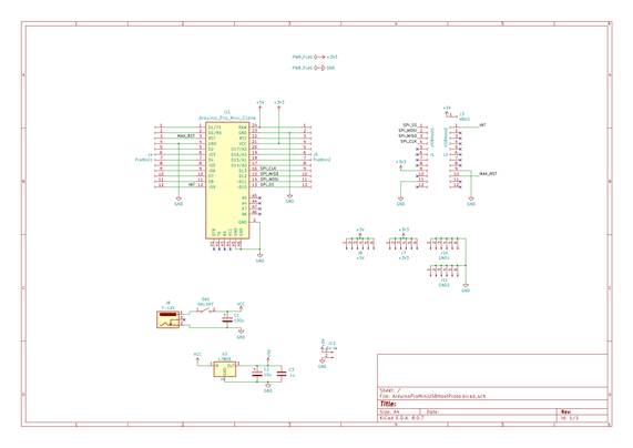
The Circuit

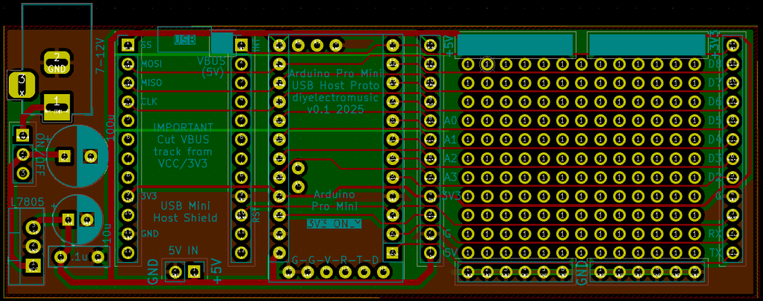
This is mostly just breaking out the pins for an Arduino Pro Mini onto a set of additional headers for use with a mini USB Host shield.

There are additional headers for power and GND and it includes the option for powering via a 7-12V barrel jack into via a 7805 regulator or directly via 5V into a set of jumper header pins.

PCB Design

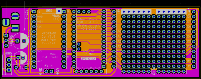
In previous designs I’ve opted to assume that the USB host shield will be mounted directly onto the Arduino Pro Mini, but this time I’ve separated them out for more flexibility.

I may decide I should have just left them together, but I didn’t think I’d be able to use pin headers and sockets in quite the same way with the headers already connecting two boards.

With hindsight I’m now wondering if I should have passed through all the Arduino Pins to the shield part. As it stands, it only has the connections required for the USB host shield.

All of the pins are broken out either side of the prototyping area however, but only the usable pins have been labelled.

Closing Thoughts

This was a somewhat speculative build based on the idea that I’d want to experiment with a USB host device and some additional circuitry.

But my main need has been satisfied by an alternative build (more on that later), so for now this is probably a “why not, might come in useful” build.

Kevin

#arduinoProMini #pcb #usbHost

Simple DIY Electronic Music Projectsdiyelectromusic.com@diyelectromusic.com
2024-07-25

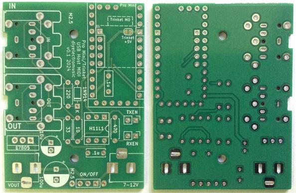
Here are the build notes for my Arduino Pro Mini MIDI USB HOST PCB.

Warning! I strongly recommend using old or second hand equipment for your experiments.  I am not responsible for any damage to expensive instruments!

If you are new to microcontrollers, see the Getting Started pages.

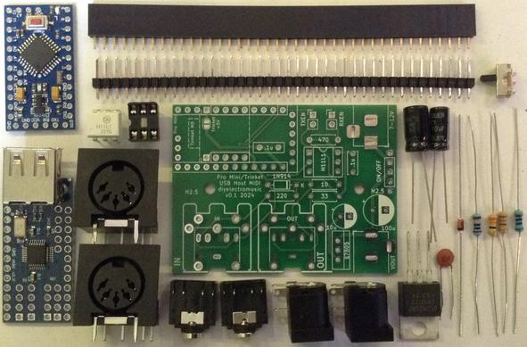
Bill of Materials

  • Arduino Pro Mini MIDI USB HOST PCB (GitHub link below).
  • EITHER: Arduino Pro Mini 3V3/8MHz version plus mini USB Host shield (see photo).
  • OR: Adafruit Trinket M0 plus “OTG” adaptor (see below).
  • 1x H11L1 optoisolator.
  • 1x 1N914 or 1N4148 signal diode.
  • 1×10Ω, 1×33Ω, 1×220Ω, 1×470Ω resistors.
  • 2x 100nF ceramic capacitors.
  • 1x 10uF electrolytic capacitor.
  • 1x 100uF electrolytic capacitor.
  • 1x 7805 regulator TO-220 format.
  • EITHER: 2x 5-pin MIDI DIN sockets (pcb mount, see photos for footprint)
  • OR: 2x 3.5mm stereo TRS sockets (pcb mount, see photos for footprint).
  • 2x 2.1mm barrel jack sockets (pcb mount, see photos for footprints).
  • 1x 6-pin DIP socket (optional).
  • 1x 3-pin slider switch (optional).
  • 2x jumpers.
  • Pin headers.
  • Pin header sockets for microcontroller (optional).

Build Steps

Taking a typical “low to high” soldering approach, this is the suggested order of assembly:

  • All resistors and diode.
  • DIP socket and TRS sockets (if used).
  • Disc capacitors.
  • Slider switch (2.54mm pitch connectors).
  • Jumper headers.
  • Pin header sockets for microcontroller (if used).
  • Barrel jack sockets.
  • Electrolytic capacitors.
  • 7805 regulator.
  • DIN sockets.
  • Microcontroller (see notes if using the Arduino Pro Mini).

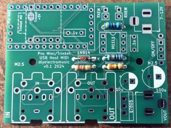
Here are some build photos.

The capacitor within the footprint of the Arduino Pro Mini has to be mounted flat. Alternatively it could be mounted on the underside of the board.

If TRS sockets are required, these are added next.

Otherwise continue on with the other components in whatever order appears to make sense.

Adafruit Trinket M0 Version

If the Adafruit Trinket M0 is used that can be added directly into the appropriate sockets.

IMPORTANT: The Trinket requires power via one of its pins which overlaps with the footprint of the Arduino Pro Mini. This means that the following solder jumper must be soldered to make the link to the 5V in.

The Trinket itself should be mounted as shown below. The photos also show a “USB OTG” adaptor which will also be required.

Arduino Pro Mini Version

The Pro Mini needs connecting to the mini USB Host shield, but before that there is one patch required to the USB Host shield to allow it to support 5V USB operation.

As it comes, the USB VCC line is connected to the main power line of the USB Host shield, but as the shield runs at 3V3 volts, this means USB is also running at 3V3 volts. This apparently can work for many devices, but not all, but there is a way to support 5V operation when used with an Arduino Pro Mini as long as the Pro Mini is powered via its RAW input with a 5V supply. This is what I’m doing here.

To enable 5V option, a PCB trace has to be cut as shown below (just down and to the left of the first hole near the top of the board next to the USB socket).

Header pins link the two boards together, but they will also have to be used to connect to the main PCB. I’ve used normal sized header pins, but notice how they are soldered on “upside down” – i.e. the longer part of the pin is above the PCB and that is the side that is soldered on.

Then the VBUS pad/connector needs patching over to the pin to hook up to the RAW connection on the Pro Mini.

I’ve mounted the Arduino on top of the shield. If the Arduino hasn’t been programmed, then programming header pins will also be required.

Warning: If using a programmer with a slider switch to select between 5V and 3V3, the cheap ones (like the one I have) DO NOT change the VCC voltage – only the UART logic levels. For mine, I need to select 3V3 via the slider switch and then connect 5V to RAW not to the VCC programming input. Check the voltages prior to using if you’re not sure.

With no VCC/5V connection once the Arduino is installed I can only reprogram it if it is powered independently of the USB programming link – i.e. via the barrel jack.

Additional MIDI Indicator

Once I started testing it, I wanted to enable a MIDI LED. Usually I’d use the built-in LED for this, but that is on pin D13 which is in use for the SPI interface to the USB host shield.

Instead I soldered on an LED and 1K resistor between D2 and GND as shown below.

The anode (long leg) of the LED is soldered to D2 and the resistor is soldered between the LED and GND.

Testing

I recommend performing the general tests described here: PCBs.

It is worth checking the operation of the 5V power supply independently.

It may also be worthwhile checking the operation of the USB host functionality on the microcontroller prior to fixing to the board.

PCB Errata

There are the following issues with this PCB:

  • The silkscreen for the on/off switch implies (to me) that up is “off”, but up is actually “on”. I’d either label it as OFF/ON or reroute the traces to match.

Enhancements:

  •  A slightly better arrangement for the MIDI sockets could be on opposite sides of the board. This could allow for a MIDI and power IN on one side and MIDI and power OUT on the other. However, if used standalone, then actually having them side-by-side possibly makes more sense anyway.
  • I can’t use the on-board LED for indications as that is on D13 which is required for the SPI link to the host board, so incorporating an additional LED would be useful.
  • It might also be useful to have a RAW/5V IN header for direct powering of the board, especially when programming in situ.

Find it on GitHub here.

Sample Applications

The Arduino can be programmed using the following:

The Trinket can be used with the following:

Closing Thoughts

In the video at the start of this post you can see my board being used to power and drive (over MIDI) my Shruthi, which to be honest, was the main reason for making it!

Now I just need to make a couple of neat, custom MIDI and power cables to link the two together.

Kevin

https://diyelectromusic.com/2024/07/25/arduino-pro-mini-midi-usb-host-pcb-build-guide/

#arduinoProMini #midi #pcb #shruthi #trinket #usbHost #usbHostMidi

Simple DIY Electronic Music Projectsdiyelectromusic.com@diyelectromusic.com
2024-07-25

I’ve finally decided to create a PCB for my Mini USB-MIDI to MIDI USB Host MIDI converter based on an Arduino Pro Mini and a Mini USB Host Shield.

Whilst I was at it, I’ve also included an option to support the USB-MIDI to MIDI Revisited build based on an Adafruit Trinket M0.

Warning! I strongly recommend using old or second hand equipment for your experiments.  I am not responsible for any damage to expensive instruments!

If you are new to microcontrollers, see the Getting Started pages.

The Circuit

This essentially provides a 3V3 Arduino Pro Mini or Trinket M0 serial MIDI interface with a built-in power regulator to generate a 5V supply. Both the Arduino Pro Mini and Trinket M0 have a “RAW” power input, but unlike many 5V microcontroller dev boards, these only accept up to around 6V.

In order to support MIDI USB host functionality, the Arduino Pro Mini requires a mini USB Host shield (see photos in the build guide, these are readily available online); the Trinket M0 can support it directly using a simple USB OTG adaptor.

I’ve include power in and out sockets to allow power “pass through” if used with another device.

PCB Design

The board will support either the 3V3 Pro Mini or the Trinket M0, so an overlapping footprint is provided for them both.

One complication is that the Trinket’s power pin overlaps with a standard IO pin when used with a Pro Mini. I’ve solved that by including a solder bridge between that pin and 5V. The default is unbridged, so set for the Pro Mini.

Pin headers for jumpers have been provided to disable the UART RX/TX from the MIDI circuit to allow for programming, although programming will be a lot easier with the devices removed from the board anyway – especially as the Pro Mini requires an external programmer.

I’m still struggling with a sensible footprint for an on/off switch, but I’ve picked one that I think matches some switches I have on order!

The footprint allows for either TRS or serial DIN MIDI sockets.

Closing Thoughts

I’m hopeful this will work ok as both variants of the board have been shown to work in proto-board or breadboard projects in the past.

Kevin

https://diyelectromusic.com/2024/07/25/arduino-pro-mini-midi-usb-host-pcb-design/

#arduinoProMini #midi #pcb #trinket #usbHost #usbHostMidi

Ansgar Schmidt :verified:Ansi@mastodon.cloud
2022-06-11
2021-10-01

Giant Working NERF Gun Runs on Tiny Arduino

Well, here it is: a shoe-in for the new world's largest NERF gun. (Video, embedded below.) The Guinness people haven't shown up yet to award [Michael Pick], but at 12.5 feet, this baby is over twice as long as the current record holder, which belongs to former NASA mechanical engineer Mark Rober and his now-puny six-foot six-shooter.

We have to wonder if it is technically bigger than the six-shooter, because they seem to be roughly the same scale, except that [Michael] chose a much bigger model to start from. The main body is made from wood, and there are a ton of 3D-printed details that make it look fantastically accurate. The whole thing weighs over 200 pounds and takes at least two people to move it around. We especially love the DIY darts that [Michael] came up with, which are made from a PVC tube inside a section of pool noodle, topped off with a 3D printed piece for that distinctive orange cap.

Propelling those darts at around 50 MPH is a 3,000 PSI air tank connected to an Arduino Pro Mini that controls the trigger and the air valves. While [Michael] hasn't run the thing quite that high, it does plenty of damage in the neighborhood of 40-80 PSI. As you'll see in the video after the break, this is quite the ranged weapon. Watch it blow a hole clean through a sheet of drywall and much more.

Want to build something with a bit more stealth? Make it death from above with a NERF quadcopter.

#arduinohacks #weaponshacks #arduino #arduinopromini #nerfgun #poolnoodle #pvc #worldslargest

image
2021-07-15

DIY PECS Board Uses Pictures to Communicate

One way of communicating with autistic and non-verbal people is through the use of a Picture Exchange Communication System or PECS board, which they can use to point out what they need or want throughout the day. However, the commercial versions of these boards have their share of problems -- they're expensive, and they're fairly rigid as far as the pictures go. [Alain Mauer] has created an open-source PECS board that is far more personalized, and has audio to boot.

The number one requisite here is sturdiness, as [Alain]'s son [Scott] has already smashed two smartphones and a tablet. [Alain] went with a laser-cut MDF enclosure that should last quite a while. Inside is an Arduino Pro Mini and a DF Player Mini that plays corresponding clips from a micro SD card whenever [Scott] presses a button on the 16-key copper foil capacitive keypad. This PECS board is smart, too -- it will sound a turn-me-off reminder after a few minutes of inactivity, and issue audible low battery warnings.

So far, [Scott] is responding better to photographs of objects than to drawings. Watch him interact with the board after the break.

This is far from the first thing [Alain] has built to help [Scott]. Be sure to check out this Pi-based media player built to engage and not enrage.

#arduinohacks #arduino #arduinopromini #autism #communication #dfplayer #mdf #nonverbalcommunication

image
2021-06-16

Sunlight-Based Life Clock Predicts Your Darkest Hour

The past year has been quite a ride for everyone on Earth. But you never know which day is going to be your last, so you might as well live a little, eh? This clock doesn't actually know when you'll kick off, either. But just for fun, it predicts the number of years remaining until you go to that hackerspace in the sky by hazarding a guess that's based on your current age and the latest life expectancy tables. Don't like the outcome? It's completely randomized, so just push the button and get a set of numbers: the age you might die, and the percentage of life elapsed and remaining.

We love the design of this calculated doom clock, and it's quite simple inside -- an Arduino Pro Mini outputs the graph on an 2.9″ e-paper display, and both are powered with a 5.5 V solar panel. Just suction cup that puppy to the window and you'll get automatic updates about your impending demise on sunny days, and none on cloudy days.

Want a more realistic picture of your mortality? Here's a clock that counts down to your 80th birthday.

The HackadayPrize2021 is Sponsored by:

#arduinohacks #clockhacks #solarhacks #thehackadayprize #arduino #arduinopromini #epaper #epaperdisplay #lifeexpectancy

image
2021-05-07

Auto Strummer Can Plectrum the Whole Flat-Strumming Spectrum

Playing the guitar requires speed, strength, and dexterity in both hands. Depending on your mobility level, rocking out with your axe might be impossible unless you could somehow hold down the strings and have a robot do the strumming for you.

[Jacob Stambaugh]'s Auto Strummer uses six lighted buttons to tell the hidden internal pick which string(s) to strum, which it does with the help of an Arduino Pro Mini and a stepper motor. If two or more buttons are pressed, all the strings between the outermost pair selected will be strummed. That little golden knob near the top is a pot that controls the strumming tempo.

[Jacob]'s impressive 3D-printed enclosure attaches to the guitar with a pair of spring-loaded clamps that grasp the edge of the sound hole. But don't fret -- there's plenty of foam padding under every point that touches the soundboard.

We were worried that the enclosure would block or muffle the sound, even though it sits about an inch above the hole. But as you can hear in the video after the break, that doesn't seem to be the case -- it sounds fantastic.

Never touched a real guitar, but love to play Guitar Hero? There's a robot for that, too.

#arduinohacks #musicalhacks #28byj48 #arduino #arduinopromini #bipolarsteppermotor #blinkenbuttons #guitar #steppermotor #strumming

image
heise online (inoffiziell)heiseonline@squeet.me
2018-05-16
Glückwunschkarten waren gestern. Stattdessen verschenken wir einen winzigen Computer, der Geburtstagsgrüße als Animation auf dem Bildschirm anzeigt. Vom 3D-gedruckten Gehäuse bis zum Arduino-Sketch ist alles selbst konzipiert. www.heise.de/make/artikel/Ardu… #3D-Drucker #Arduino #ArduinoProMini #Macintosh128K
heise online (inoffiziell)heiseonline@squeet.me
2018-03-07
Schnurren und rumfläzen klappen schon, nur mit dem Springen hat es die Roboterkatze Petoi noch nicht so. Wer in dem Raspi-Projekt Amazons Alexa einbindet, könnte seinen Stubentiger bald auch das Wetter ansagen oder die Heizung einschalten lassen. www.heise.de/make/meldung/Robo #Arduino #ArduinoProMini #OpenCat #Petoi #RaspberryPi #RaspberryPi3

Client Info

Server: https://mastodon.social
Version: 2025.04
Repository: https://github.com/cyevgeniy/lmst