ESP32 S3 DevKit Experimenter PCB Build Guide
Here are the build notes for my ESP32 S3 DevKit Experimenter PCB Design.
Warning! I strongly recommend using old or second hand equipment for your experiments. I am not responsible for any damage to expensive instruments!
If you are new to electronics and microcontrollers, see the Getting Started pages.
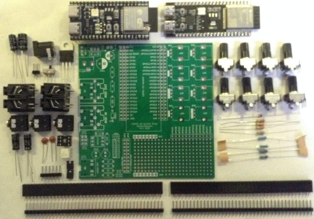
Bill of Materials
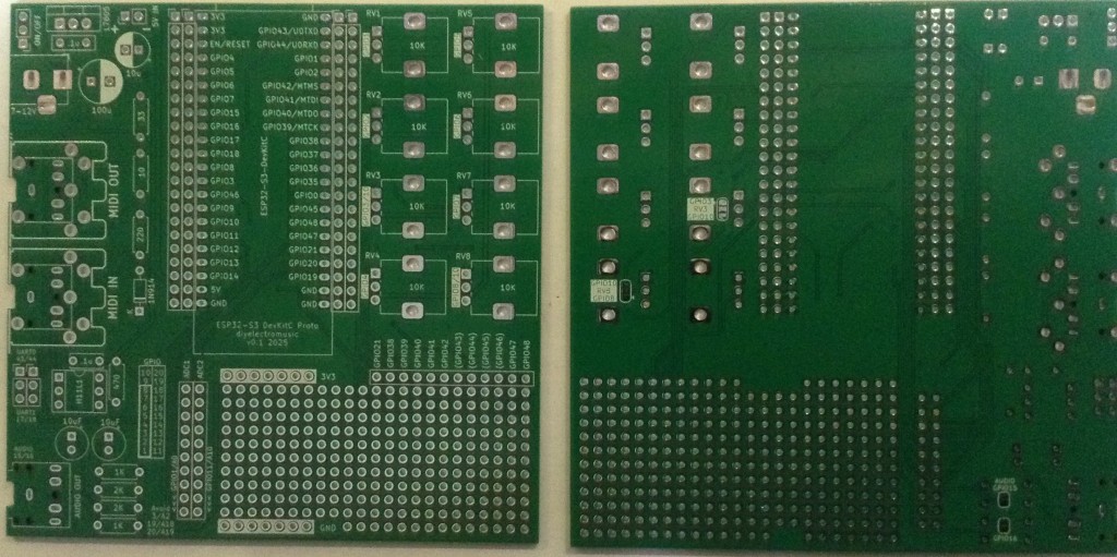
- ESP32S3 DevKit Experimenter PCB (GitHub link below)
- ESP32S2 DevKitC (official or clone – see ESP32 S3 DevKit)
- MIDI Circuit:
- 1x H11L1 optoisolator
- 1x 1N4148 or 1N914 signal diode
- Resistors: 1x 10Ω, 1x 33Ω, 1x 220Ω, 1×470Ω
- 1x 100nF capacitor
- Either: 2x MIDI DIN sockets (see photos and PCB for footprint)
- Or: 2x 3.5mm stereo TRS sockets (see photos and PCB for footprint)
- Pin headers and jumpers
- Optional: 6-way DIP socket
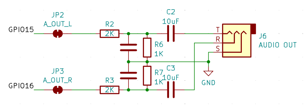
- Audio Output Circuit:
- Resistors: 2x 1K, 2x 2K
- 2x 10uF non-polar capacitors
- 2x 33nF ceramic capacitors
- 1x 3.5mm stereo TRS socket
- Power Circuit:
- 1x 7805 regulator
- Electrolytic Capacitors: 1x 100uF, 1x 10uF
- 1x 100nF Ceramic Capacitor
- SPST switch with 2.54mm pitch connectors
- 2-way header pins
- 2.1mm barrel jack socket (see photos and PCB for footprint)
- 8x 10K potentiometers (see photos and PCB for footprint)
- Optional: 2x 22-way pin header sockets
- Additional pin headers or sockets as required
Each circuit module is effectively optional. The position of the 22-way headers will depend on which type of module is used. The clone versions are 1 pin row wider than the official version.
There are some solder-bridge configuration options too, which will be discussed later.
Build Steps
Taking a typical “low to high” soldering approach, this is the suggested order of assembly:
- All resistors and diode.
- DIP socket (if used) and TRS socket(s).
- Disc capacitors.
- Switch
- Jumper and pin headers.
- 22-way pin sockets (if used).
- Non-polar and electrolytic capacitors.
- 7805 regulator.
- Potentiometers.
- DIN sockets.
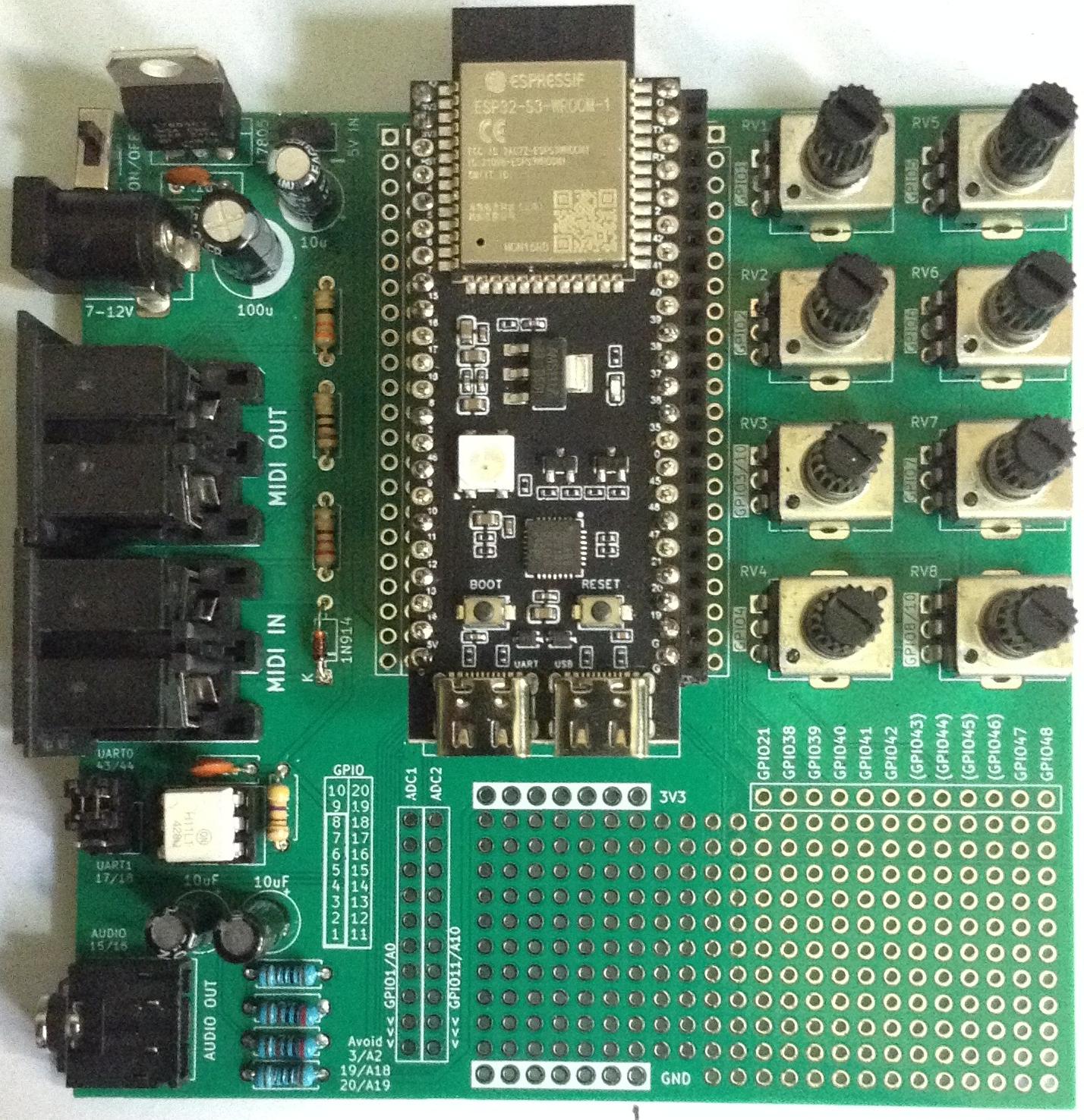
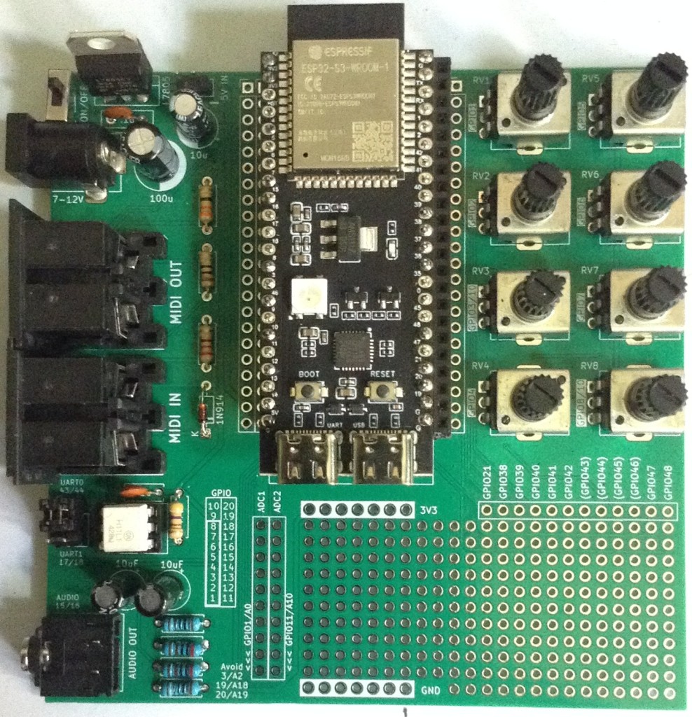
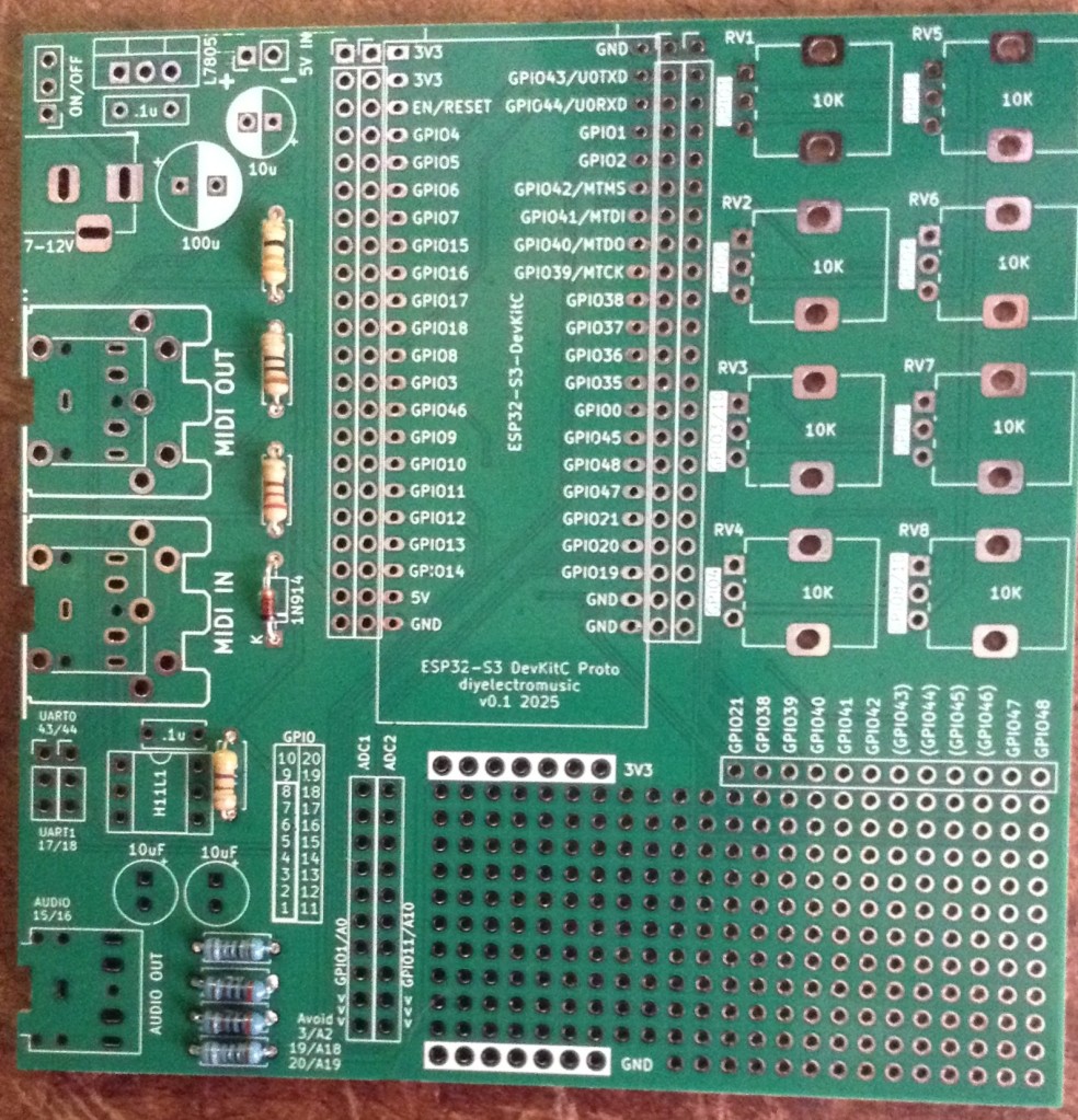
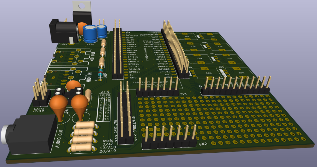
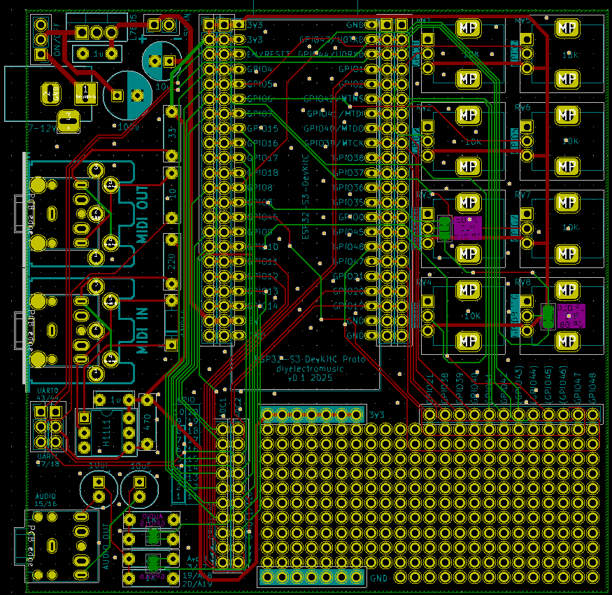
Here are some build photos for the MIDI DIN version of the board. If using MIDI TRS sockets, then these can be installed at the same time as the audio socket.
If using 22-way headers for the DevKit, then the position will depend on which type of DevKit module is being used. In the photo below, I’ve installed 3 sets of 22-way headers to allow me to use either a clone or official module.
The remaining components can almost be installed in any order that makes sense at the time.
Once the main build is complete, two additional capacitors are required for the audio PWM output circuit. Two 33nF capacitors should be soldered across the 1K resistors. This is probably best done on the underside of the PCB as shown below.
Ignore the red patch wire. I managed to cut through a track whilst clipping the excess leads after soldering.
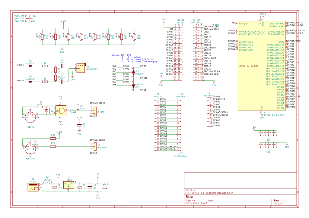
Configuration Options
The following are configurable and can be set by using pin headers and jumpers; solder bridges; or possibly wire links.
- UART for MIDI – pin header + jumpers.
- Audio Output – can be disconnected by breaking solder jumpers on rear of the board under 1K/2K resistors.
- GPIO used for RV3 and RV8 – can be set using solder jumpers on rear of the board under RV3 and RV8.
Testing
I recommend performing the general tests described here: PCBs.
WARNING: The DevKit can be powered from either the USB sockets or the new power circuit, but not both at the same time.
The sample application section includes some simple sketches that can be used to test the functionality of the board.
PCB Errata
There are the following issues with this PCB:
- I should have oriented the DevKit the other way up so that the USB sockets were on the edge of the board, not overhanging the prototyping area!
- The Audio filter requires additional capacitors (see notes).
Enhancements:
Find it on GitHub here.
Sample Applications
Analog Potentiometers
The following will read all 8 pots and echo the values to the serial monitor.
void setup() {
  Serial.begin(115200);
}
void loop() {
  for (int i=0; i<8; i++) {
    int aval = analogRead(A0+i);
    Serial.print(aval);
    Serial.print("\t");
  }
  Serial.print("\n");
  delay(100);
}
Audio PWM Output
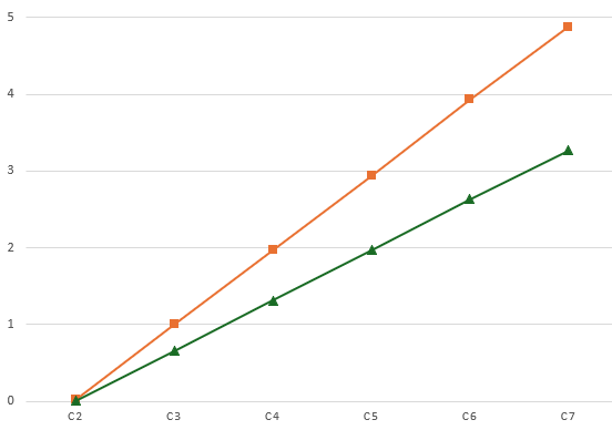
The following will output a 440 Hz sine wave on the PWM channel on GPIO 15. Change to 16 to see the other one.
int pwm_pin = 15;#define NUM_SAMPLES 256uint8_t sinedata[NUM_SAMPLES];#define PWM_RESOLUTION 8#define PWM_FREQUENCY 48000#define TIMER_FREQ 10000000#define TIMER_RATE 305#define FREQ2INC(f) (f*2)uint16_t acc, inc;void ARDUINO_ISR_ATTR timerIsr (void) { acc += inc; ledcWrite (pwm_pin, sinedata[acc >> 8]);}hw_timer_t *timer = NULL;void setup () { ledcSetClockSource(LEDC_AUTO_CLK); for (int i=0; i<NUM_SAMPLES; i++) { sinedata[i] = 127 + (uint8_t) (127.0 * sin (((float)i * 2.0 * 3.14159) / (float)NUM_SAMPLES)); } timer = timerBegin(TIMER_FREQ); timerAttachInterrupt(timer, &timerIsr); timerAlarm(timer, TIMER_RATE, true, 0); ledcAttach(pwm_pin, PWM_FREQUENCY, PWM_RESOLUTION); inc = FREQ2INC(440);}void loop () { }I’m getting a pretty good signal with a 33nF filter capacitor, but the signal still retails some bias. I’m getting a Vpp of around 1.1V.
But it starts out with a swing from around -200mV to +900mV. But this slowly improves over time and after a few minutes is much closer to a nominal -500mV to +600mV. I guess that is probably my cheap capacitors!
MIDI
Most of the MIDI monitors, routers and sending projects I have should work with the MIDI setup. In the default configuration, using UART0 (GPIO 43/44) for MIDI, that appears as Serial0 or the default MIDI configuration (more on serial ports on the ESP32S3 here: ESP32 S3 DevKit).
So the Simple MIDI Serial Monitor should just work and anything sent to the board should:
- Illuminate the on-board (RGB) LED.
- Echo back out to the MIDI OUT port.
Here is the full test code:
#include <MIDI.h>

MIDI_CREATE_DEFAULT_INSTANCE();

void setup() {
  MIDI.begin(MIDI_CHANNEL_OMNI);
  pinMode (LED_BUILTIN, OUTPUT);
}

void loop() {
  if (MIDI.read()) {
    if (MIDI.getType() == midi::NoteOn) {
        digitalWrite (LED_BUILTIN, HIGH);
        delay (100);
        digitalWrite (LED_BUILTIN, LOW);
    }
  }
}
Note: as the MIDI is (probably) hanging of UART0 which is also routed to the USB “COM” port, it will be easier to upload via the USB “USB” port. This won’t clash with the MIDI circuitry on UART0.
Closing Thoughts
I seem to be having a run of “doh” moments with a few of these PCBs, but then that is the price I pay for taking shortcuts by only designing them in my head rather than prototyping them first!
But arguably, it is still a lot easier using a soldered PCB than attempting to build the various elements on solderless breadboard, so in a way that is what these prototypes are largely for.
So apart from the filter issue which is actually fairly easily solved, this seems to work pretty well.
Kevin
#define #ESP32s3 #include #midi #pcb #potentiometer #pwm