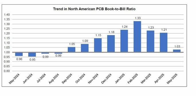
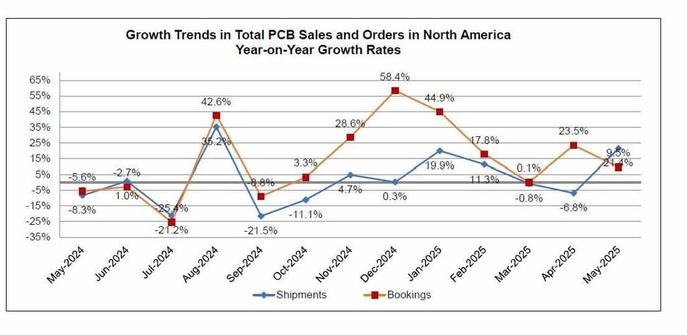
【統計情報】6月20日に、米国 #IPC が北米プリント回路基板(PCB)統計プログラムの5月分調査結果 https://www.electronics.org/news-release/north-american-pcb-industry-sales-214-percent-may を発表。BBレシオは1.03に急減。出荷額は前年同月比で21.4%増加、前月比で7.1%増加、年累計は前年比7.9%増加。受注額は前年同月比で9.5%増加、前月比で12.9%減少、年累計は前年比18.3%増加。
#NorthAmerica #PCB #Statistics
#pcb
All 19 Designs 👀✨
uh-oh
with 6-layer #PCB designs the prototyping becomes really costly.
50 pcs cost less than twice the price of 5.
economy of scale. economy of exponential scale.
OK, no errors this time I guess!
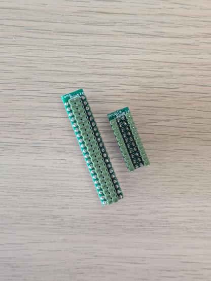
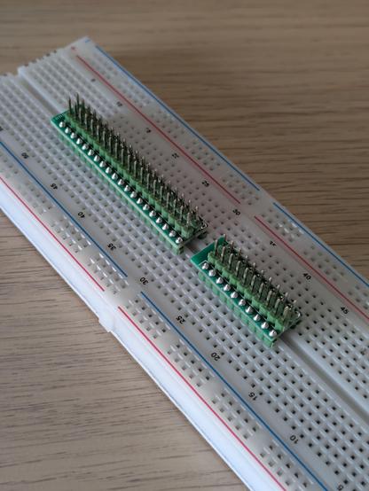
Presenting: the double-double and the long-double, two small PCBs intended to break out a two-by-something row of pins to either side of a breadboard. (They are also great for precise soldering practice - just ignore the fact I did one of them upside down.)
There's probably better ways to solve this, but this is mine.
I'm getting close to publishing my portfolio site and these will be on there as files you can download and send off to be made.
STM32 Unboxing #1 - JLCPCB Goody Bag
My first (!!! - and possibly last) unboxing video - didn't go particularly well. Recorded on my phone on my balcony - audio is pretty horrible and for some unknown reason out of sync. Anyway - the box was full of Goodies from JLCPCB (described in last video). PCB's ordered last Monday and I had them today - exactly 1 week later.
#STM32 #Gettingstarted #Tutorial #KiCAD #PCB #JLCPCB #stm32world
DRITTI CONTRO IL CIELO: BOLOGNA OSPITA IL PALESTINIAN YOUTH CLUB DI SHATILA https://www.radiocittafujiko.it/dritti-contro-il-cielo-bologna-ospita-il-palestinian-youth-club-di-shatila/ #PCB–PallacanestroCooperativaBologna #PolisportivaHicSuntLeones(HSL) #PalestinianYouthClubShatila #CentroStoricoLebowki #ATTUALITA'EPOLITICA #PalestraPopolareTPO #Sportbeatsborders #NoBorderCup2025 #HayatAPS #ITALIA
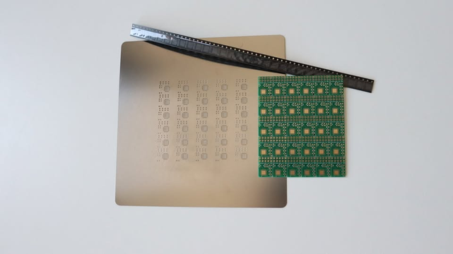
🕵️♂️ What’s this? A glimpse into a new Raspberry Pi add-on board. 👀🔐
We have a panel of PCBs and a stencil. TPM 2.0 meets open source hardware… something tiny is securely brewing. Stay tuned. ⚡️🧩
#RaspberryPi #opensource #kicad #PCB
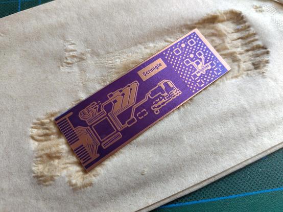
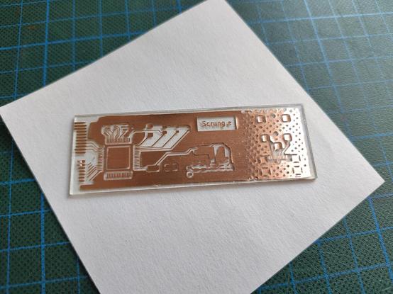
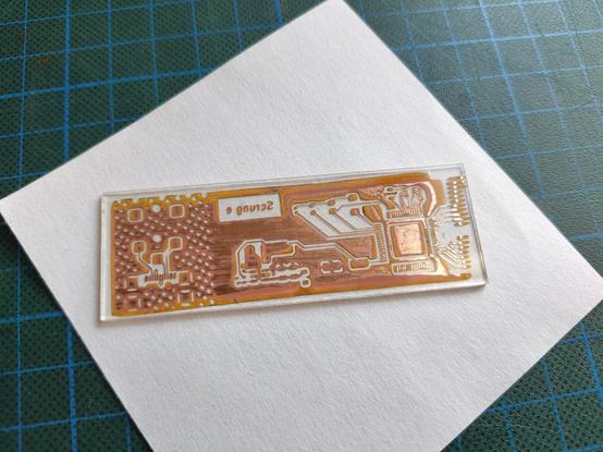
ok, copper tape glass PCB test results are in. just did a small test layout with some traces and test footprints. exposure and development of the etch resist went well. 7.5 minutes under my UV box and development in water with a random amount of sodium carbonate in it.
etching went… less than well. The glue on the tape does not seem to stand up to the copper chloride etchant very well and there was severe under etch all around the edges and a whole bunch of delamination. might have to try a different way of attaching copper foil. one option might be to just use the same material as the etch resist as glue…
oh yeah, and even though the glue was kinda destroyed by the etchant there is still a layer of glue on all the bare glass spots :I
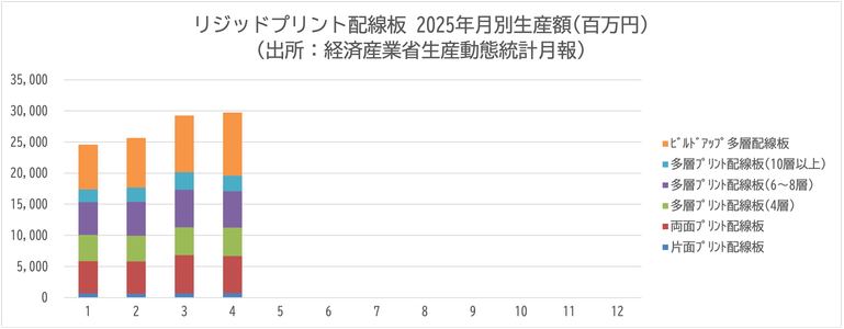
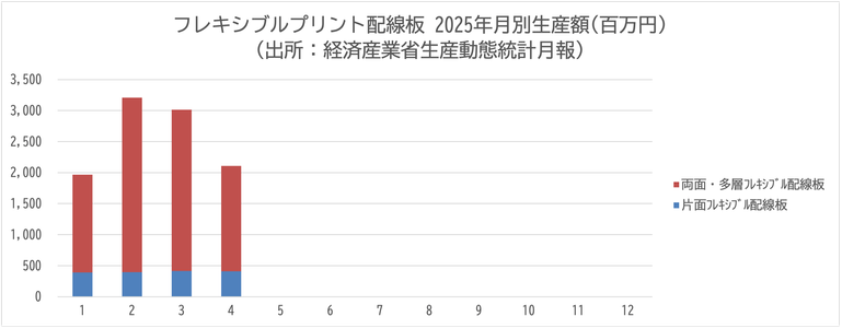
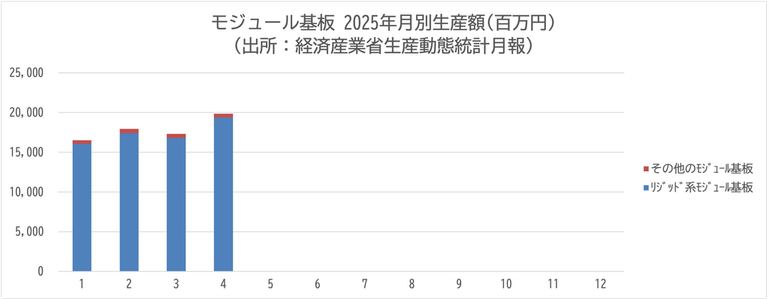
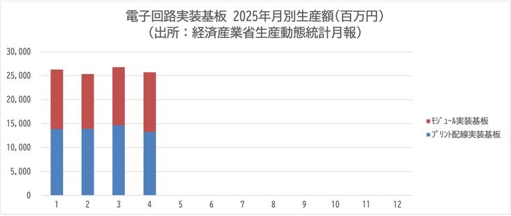
【統計情報】6月19日に日本電子回路工業会 #JPCA が電子回路基板・電子回路実装基板の生産動向資料を更新。2025年4月実績を追加。経済産業省・生産動態統計月報(6月13日公表)による。数量と金額のデータとグラフは https://www.jpcashow.com/kikaitoukei/kikai_toukei.xlsx に(Excel, 191KB)。
#PCB #PCBA #Statistics
After the last development update, NLnet granted us additional 10 000 EUR for new tasks. For this money, we have implemented some experimental features, which are covered in the below sections.
Meanwhile, we are also working hard to complete all the unfinished features and fix as many bugs as possible to release Topola v0.1, the first alpha version of the Topola PCB router, which we hope to accomplish by the end of this year.
https://topola.dev/blog/2025/06/19/june-2025-development-update/
Dibujar las pistas de un circuito #PCB es un arte. Eso es asín. Y si no estás de acuerdo estás equivocado 🙃
STM32 Short #4 - Exciting Plans
Just a short announcement of some exciting development.
The KiCad team outlines serious Wayland limitations, including window control and crashes, urging users to stick with X11 desktops for reliability.
https://linuxiac.com/kicad-advises-linux-users-to-stick-with-x11-for-professional-pcb-design/
Check out our playlist on Youtube on how to design a #PCB in #KiCAD from scratch. The first video cover schematics, second video the PCB and #Routing, and the third video how to order on #JLCPCB.
https://www.youtube.com/playlist?list=PLVfOnriB1RjW1bjvfdfvBH_yly3bV6s8T
@mvniekerk Haven‘t tried eurocircuits yet, but plan to. They are from Belgium with production in Germany and Hungary. Try to avoid Chinese stuff, but it is hard. #pcb #assembly #ic #smd
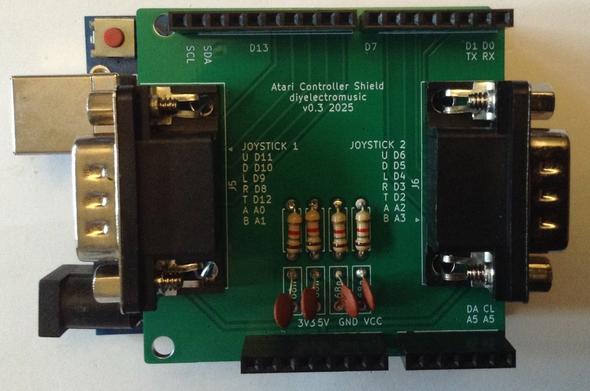
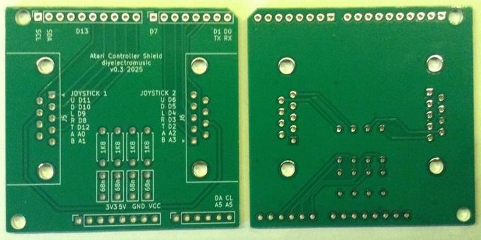
Atari 2600 Controller Shield PCB Revisited
As previously mentioned in my Atari 2600 Controller Shield PCB Build Guide the PCB doesn’t work so well with paddle controllers due to the way they are wired up.
This is an update to the PCB to allow the paddles to be used in a very similar way to the original Atari 2600.
Warning! I strongly recommend using old or second hand equipment for your experiments. I am not responsible for any damage to expensive instruments!
If you are new to Arduino, see the Getting Started pages.
PCB Update
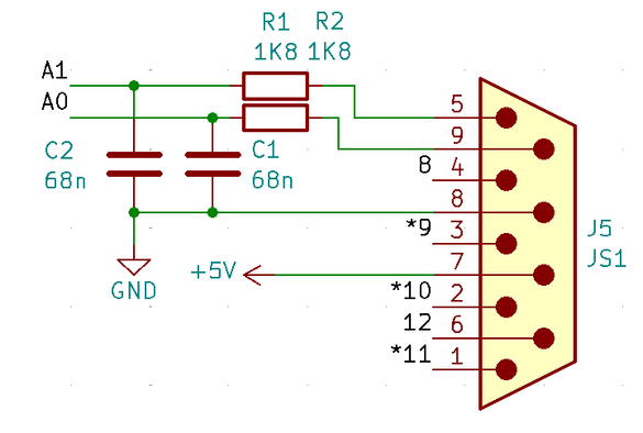
This is basically the PCB design as described here: Atari 2600 Controller Shield PCB Design but with the addition of a resistor and capacitor in the paddle circuit as shown below.
These are the values used in the original Atari circuit as can be found in the following references:
- Atari 2600 main circuit: https://atariage.com/2600/archives/schematics/Schematic_2600_Low.html
- Atari 2600 paddle circuit: https://atariage.com/2600/archives/schematics/Schematic_2600_Accessories_Low.html
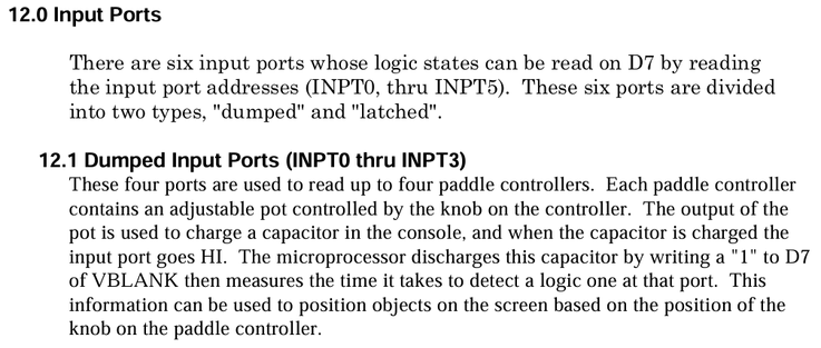
- Details of programming for paddles: “Stella Programmer’s Guide” section 12.1, TIA section 8B, Figure 8.
These also describe the operation of the TIA and paddle INPUT circuit:
The block diagram for the TIA shows the transistors mentioned, that are controlled by D7 in VBLANK.
The basic idea being described is that setting D7 turns on the transistors that will drop the voltage from the capacitor to zero. Then the capacitor will charge again and the time it takes to charge depends on the position of the paddle, which is connected to a 1M variable resistor. By measuring the time it takes to charge the capacitor back up, the position of the paddle can be determined.
From all this, we can conclude that the required approach for an Arduino should be as follows (assuming the paddles are connected to analog INPUT ports):
SET pin to OUTPUT
SET pin to LOW
SET pin to INPUT
Start timer
WAIT WHILE (voltage on the analog INPUT pin is NOT HIGH)
Stop timer
This works because the ATmega328P’s analog input ports (at least A0 to A5) can also be used as digital input and output ports.
Note: the Arduino reference documentation states that if swapping from digital output to analog input, then the mode should be explicitly set prior to any calls to analogRead (see “caveats” here).
Build Steps
Solder the components in the following order:
- Resistors
- Capacitors
- Arduino headers
- 9-way D-type connectors
Testing
I recommend performing the general tests described here: PCBs.
The following sketch will read the value of one of the paddle controllers, implementing the algorithm described above.
#define PAD_PIN A0

#define RAW_MAX    950
#define RAW_SHIFT  7
#define RAW_OFFSET 3
#define RAW_BREAK  150000

unsigned long atariRawAnalogRead (int pin) {
  unsigned long start = micros();
  pinMode(pin, OUTPUT);
  digitalWrite(pin, LOW);
  pinMode(pin, INPUT);
  while ((analogRead(pin)<RAW_MAX) && (micros()<(start+RAW_BREAK)))
   {}
  return (micros() - start);
}

int atariAnalogRead (int pin) {
  unsigned long val = atariRawAnalogRead(pin) >> RAW_SHIFT;
  if (val < RAW_OFFSET) {
    return 1023;
  } else if (val < 1023+RAW_OFFSET) {
    return 1023-(val-RAW_OFFSET);
  } else {
    return 0;
  }
}

void setup() {
  Serial.begin(9600);
}

void loop() {
  Serial.print(atariRawAnalogRead(PAD_PIN));
  Serial.print("\t");
  Serial.print(atariAnalogRead(PAD_PIN));
  Serial.print("\t");
  Serial.println(analogRead(PAD_PIN));
}
The configuration values at the top are determined through a bit of trial-and-error, noting the following:
- A single reading could take up to 150 mS.
- The maximum analog reading corresponds to a voltage of around 4.6V, which is around 940 out of 1023.
- Timing the charging using microseconds gives more resolution, especially at the quicker end.
- Shifting the measurement >>7 turns the up to 150,000 value into a value of up to 1170.
- The residual readings are largely in the range 3 to 1170 now, so a subtraction is required to drop that down to 0, and the top reading needs capping at 1023 to match that returned by analogRead().
- Reversing the sense of the readings means that clockwise reads higher than anticlockwise.
- Note: if not controller is plugged in, then the while loop would never complete, so a breakout timer value is provided set to the expected maximum of around 150mS.
The Arduino functions are relatively slow compared to direct register access, but as the time out involved is up to 150mS, I’m not too worried about trying to speed up the Arduino calls.
If I was attempting to read all four paddle controllers at the same time, some optimisation would be required. It might even be worth attempting to read them using a timer interrupt and a sampling routine.
- Update: This has been described here: Atari 2600 Controller Shield PCB Revisited – Part 2
If this was to be used properly, some averaging of values would also be required.
Other PCB Notes
- This PCB still works fine with keypad controllers. The additional resistor and capacitor does not affect the keypad scanning function.
- This PCB also still works fine with joysticks, as the digital lines have not be altered.
- It is possible to use this PCB with the “additional resistor” method described in Atari 2600 Controller Shield PCB Build Guide. This requires installing a resistor where the capacitor is meant to go and shorting the existing resistor link together.
Find the updated PCB on GitHub here.
Closing Thoughts
There are now several approaches that can be used to read Atari paddle controllers from an Arduino.
- Doctor the wiring of the paddles themselves to internally connect the potentiometer to the 5V and GND line, then connect it directly to an Arduino analog input like any other potentiometer.
- Use the approach described in Atari 2600 Controller Shield PCB Build Guide to add a resistor and make a variable potential divider, adjusting the read values in software.
- Use the approach described above to time the charging of a capacitor, mirroring how the original Atari circuit and TIA would have worked.
Kevin
Разработка своего компактного TerraMaster на основе Twin Lake-N и PCIe Switch
В последнее появилось много компактных NAS с основным хранилищем на SSD носителях и с десяти гигабитным Ethernet. Высокая скорость работы твердотельных дисков в связке с высокой скоростью обмена по сети, прекрасно раскрывают возможности новой техники, а самое главное оправдывают ожидания их владельцев от новых технологий. Насколько сложно самостоятельно собрать подобный NAS, используя доступные комплектующие и готовые компьютерные платформы? Как оказалось всё не так сложно, если найти подходящую платформу и немного её прокачать. Вот о такой доработке и пойдет речь.
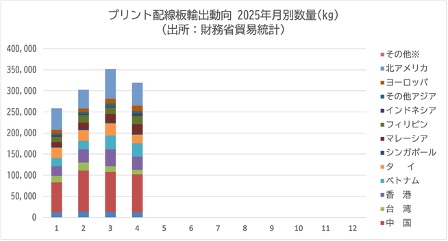
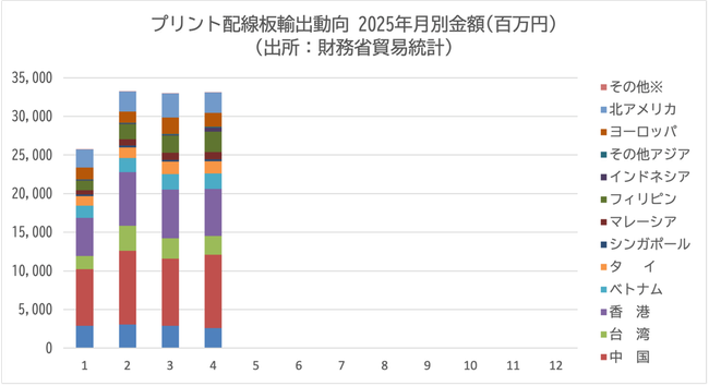
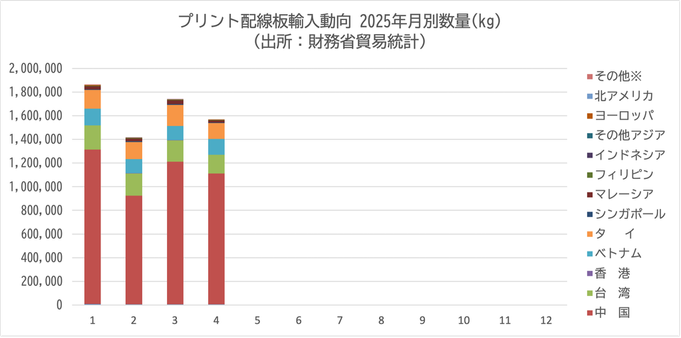
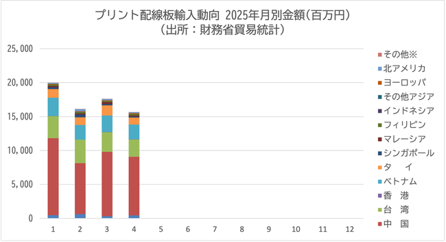
【統計情報】6月12日、日本電子回路工業会 #JPCA がプリント配線板輸出入動向を更新。2025年4月分を追加。財務省貿易統計による。数量と金額の国別データとグラフは https://jpca.jp/wp-content/uploads/yushutsunyu_toukei.xlsx に。
#Statistics #PCB #Export #Import
