#boostconverter

2024-12-09

En el contexto de los fastidiosos apagones que estamos viviendo, he comprado este cable para Router, mas que nada para entender como funcionaba, convirtiendo de 5v a 12v y permitiendo utilizar un PowerBank para alimentar un Router o Modem de internet. diez dolarazos cuesta el adefesio para lo que hace.

He desarmado este dispositivo para tratar de entender como funciona. Antes ya he desarmado mas cosas, como un proyector de juguete.

  1. Sobre el «Cable para Router»
    1. Características Técnicas
  2. Probablemente no te sirva
  3. Tecnología
  4. Conclusiones

Sobre el «Cable para Router»

El artilugio en si no tiene un nombre. Es una curiosa improvisación china basada en la necesidad de afrontar el aburrimiento de hasta doce horas de apagón con el único servicio relativamente confiable, el internet. La tarifa plana permite matarse viendo series, películas, animes o simplemente andar a la deriva por las redes sociales. Me encantaría saber si es un producto existente de mucho tiempo atrás, o es algo que se diseño sobre la marcha ante la crisis energética de mi país. Dudo que seamos tan importantes, pero esta claro que hemos causado una gran impresión sobre el mercado internacional al dejar sin abastecimiento tiendas que distribuyen fuentes de energía y bancos de baterías.

Características Técnicas

Tras un poco mas de investigación he encontrado que este tipo de cables es muy utilizado (obvio no en mi tercermundista país) para todo tipo de Juguetes. es posible encontrarlo de hecho en Amazon con el nombre de USB to DC 9V 12V Charging Cable pero también con el nombre de Universal Power Cord for Toys lo que podría explicar su bajo desempeño en requerimientos mas avanzados.

  • Conector macho USB
  • Conector Macho 12v tipo barril 2.1mm
  • Entrada: <36v 2A max
  • Salida: 12v 0.7A (8W)

Si, no hay mas specs XD

Probablemente no te sirva

O mas bien es cuestión de suerte. Seguro hay mejores cables, pero en este caso, la salida es de 0.7A. Esto significa que tu Router debe consumir menos de eso o simplemente no funcionará. O por el contrario, funcionará pero seria menos estable.

La mayoría de los Routers tienen un consumo de 12v a 0.5A, pero no siempre se da el caso. He probado con algunos de los Routers que tengo y entre otras cosas, el conector macho de 12v no siempre fue compatible o el Router requería hasta 2A, con lo que los 0.7A que ofrece este cable, simplemente no sirve.

Otro problema que encontré es que si se da el caso de que usas varios routers y quieras utilizar «el pulpo» un separador de cable de 12v, seguramente no vas a poder pues, aunque el Router sea de 0.5A, usar este cable divide la potencia para la cantidad de dispositivos conectada. Así, si tienes dos, 0.7/2 te dará 0.3A para cada uno, con lo que probablemente ni siquiera encienda.

Tecnología

El convertidor elevador​ o convertidor boost (del inglés boost converter) es un convertidor DC a DC que obtiene a su salida una tensión continua mayor que a su entrada. Es un tipo de fuente de alimentación conmutada que contiene al menos dos interruptores semiconductores (diodo y transistor), y al menos un elemento para almacenar energía (condensador, bobina o combinación de ambos). Frecuentemente se añaden filtros construidos con inductores y condensadores para mejorar el rendimiento.

Fue relativamente fácil descubrir el funcionamiento de este «cable para router» al notar el elemento inductor; el componente marcado con 4R7. La tecnología es un convertidor elevador o Boost Converter. Puedes investigar como funcionan en la wiki o preguntarselo a alguna IA. Debido a que eso es todo el circuito, no hay mucho que explicar.

La entrada, por el formato del conector USB es de 5v, pero teóricamente puedes inyectarle un rango entre 3 a 48v, da igual. La salida de amperaje esta determinada por la calidad de los componentes y su capacidad de disipación. En las pruebas que he realizado, ante el trabajo mas intenso del Router, ha comenzado a calentar y al estar encerrado en una caja plástica sin ventilación, corre el riesgo de sobrecalentar en poco tiempo.

Conclusiones

¡Hey, esto es mas seguro que soldarle el cable del router a una batería de motos!

Un Powerbank ya tiene sus sistemas de protección y las baterías de litio pueden aguantar sobredescargas sin mayores riesgos, por lo que el cable es solo el paso faltante para aprovechar esa energía almacenada. Eso significa que una batería de 20000 maH podría estar manteniendo un router de 0.5ma mas de 4 horas sin mayores sufrimientos. Las baterías de plomo sufren del efecto memoria, que hace que descargas profundas acorten la vida útil de la batería, ademas de que no hay un sistema controlador de carga que evite la descarga total ni la sobrecarga del aparato. Claro, las baterías de plomo son mas seguras que las de litio en estas circunstancias, pero ya han habido algunos incendios provocado por estos sistemas improvisados.

Si el apagón te esta haciendo sufrir demasiado, recuerda tomar precauciones manteniendo controles de seguridad y muy especialmente, manteniendo las instalaciones lejos de objetos inflamables o de niños.


https://interlan.ec/2024/12/09/diy-desarme-de-cable-para-router/

#boostConverter #cosasChinasTruchas #desarme #DIY #internet #solucionesDeEmergencia

2023-12-29

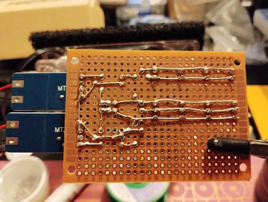
After failing to create a #symmetric #powersupply using an OpAmp and BJTs to split 24V by forming a virtual ground, I went the easy route. Two #BoostConverter set to 12V each are connected in series with the center being ground. This way I get symmetric +/-12V. Of course I don't rely on the #battery protection, but rather use a 900mA #PPTC #fuse per rail. Also a switch and some LEDs as indicator. Enough #JST sockets for my upcoming #synth projects.
#perfboard #diy #perfboard #KiCad

Schematics of my symmetric power supply. it's just a switch, fuses, and LEDs and two boost converters, done in KiCadplanned perfboard layout using KiCad PCB editorbackside of the finished perfboard. the soldering can be seen. I'm satisfied by how clean it looks.front of the finished perfboard with batteries and boost converters plugged in. the LEDs are lighting, indicating that the switch is turned on
2023-10-04

Doing a quick test of a boost converter circuit I got on Amazon. I don't think anything will go wrong, but just in case I have the shield.

This is just something quick. I wanted to grab to be able to run a thin client, which needs about 19 volts, from a 12 volt battery. It looks like it should only need a few watts, 10 watts tops from when I was measuring it under load. This is without running a desktop or anything.

#PowerElectroncis #BoostConverter

A small circuit board, a boost converter, sitting on a work bench. Two wires are attached to terminals on one side, on the other end of which are connected. Alligator clip leads. The black goes to the negative terminal of a small battery near the top of the picture, while the red is just sitting on the workbench.A plastic container turned upside down and placed over the circuit board on the workbench. From the previous picture. The two clip leads are coming out from underneath the container.
2022-04-17

A Neat Little Tool to Reset the Fuses on Your ATtiny

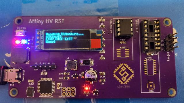
If you're an experienced hacker, you've probably run into a problem at some point and thought "let's make a tool to automate that". A few hours later you've got your tool, but then realize that the amount of work you put into making the tool vastly exceeds what you would have needed to solve the original problem manually. That really doesn't matter though: developing a fancy tool can be a rewarding experience that teaches you way more about the original problem than you would have learned otherwise. [sjm4306]'s ATtiny High Voltage Fuse Reset-er is a clever device that firmly falls into this category.

The problem it solves is familiar to anyone who's ever worked with Atmel/Microchip's ATtiny series of microcontrollers: set one of the configuration fuses incorrectly and you're no longer able to reprogram your chip. Getting the ATtiny back to its original configuration requires a high-voltage programming step that involves pulling the reset pin to 12 V in what's otherwise a 5 V system. You could simply grab a spare 12 V supply and hack together a level shifter with a few transistors, but where's the fun in that?

[sjm4306]'s solution is built on a pretty purple PCB that contains an ATmega328, an OLED display, and sockets to accommodate various versions of the ATtiny series microcontrollers. To generate the required 12 V, one could simply use an off-the-shelf boost converter IC. But instead, he decided it would be interesting to make such a circuit out of discrete components and control it using the ATmega. After all, this chip already contains timers to generate PWM signals and an ADC to measure the converter's output voltage, so all it took was to write some control logic in the form of a PID controller.

The end result, as you can see in the video embedded below, is a convenient little PCB that runs off a 5 V USB power supply and resets the fuses on your ATtiny at the push of a button. Sometimes, simple tools that do one thing well are all you need; however, if you're looking for an all-in-one AVR programmer that also supports HV programming, check out this AVR Multi-Tool.

#attinyhacks #toolhacks #attiny #boostconverter #hvprogramming

image
2021-12-02

SuperCapacitors vs Batteries Again

Supercapacitors are definitely not the same as batteries, we all know that. They tend to have a very low operating voltage, and due to their operating principle of storing charge on parallel plates, their discharge curve is quite unfriendly for modern microcontroller devices. Energy storage efficiency per unit volume is also low compared with modern lithium polymer (LiPo) batteries so all in all they don't look all that useful for many of our projects. However, as [Andreas Spiess'] latest video demonstrates, they do have some redeeming features that might make them useful for certain embedded applications.

The low operating voltage initially looks like an issue for devices operating at a typical 3.3V, and it's tempting to simply wire a few in series and roll with it. But as [Andreas] explains in his typically clear manner, it would be necessary to have a complex power stage, operating in buck mode with capacitor voltage above the required level, and in boost mode when it heads below. Too complex - it's much easier to simply stick with a low voltage bank of paralleled supercaps, and just operate always in boost mode. Even doing this, you're not realistically going to get more than a handful of hours operating voltage with an always active device.

So why bother at all with supercaps, surely using a LiPo is so much easier and better? In many cases the answer is definitely a yes. But LiPo cells must not be charged in freezing temperatures (apart from certain special low temp products), else the cell can rapidly be destroyed due to lithium metal deposition at the anode. Also you need to be careful charging them, especially when they're heavily discharged, as they are easily damaged without the proper treatment. LiPo cells operate based on chemical principles - lithium ions literally have to move around inside the structure, and eventually the battery will wear out.

Supercapacitors have the advantage of very long life (but sometimes, they do leak) much more aggressive charging and discharging behaviours and will operate down to very low temperatures. This makes them very useful when a large amount of power is available sporadically (for super fast charge cycles) or in places where temperatures stay persistently very low, such as up a mountain were solar will work, albeit slowly, but LiPo batteries will definitely not be suitable.

Other battery chemistries are available, such as Lithium Iron Phosphate which can tolerate the cold. Also you can always just insulate the battery with an integrated heater and preheat the battery to a safe charging temperature as well. So, just like everything with electronics, it's important to choose the correct parts for your application, and it all starts with the power source. Supercapacitors might just hit an appropriate price/performance point for that special application you had in mind.

Supercapacitors aren't really suitable for many applications, like powering an eBike or running your laptop, but hey, they did it anyway.

#hardware #boostconverter #lipobattery #supercapacitor

image
2021-11-29

Scrolling Name Badge Is Sure to Break the Ice

Most makerspaces and hackerspaces have one night per week or month where the 'space is open to the public in order to entice new people into joining up. Whereas most members just write their name in Sharpie on a piece of masking tape, [Madison] wanted to do something extra. And what better way to get people interested in your 'space than by wearing something useful that came out of it?

The badge runs on an ATtiny45 and uses three 8×8 ultra-bright LED matrices for scrolling [Madison]'s name. It's powered by a tiny LiPo battery that is boosted to 5 V. This build really shows off a number of skills, especially design. We love the look of this badge, from the pink silkscreen to the the typography. One of the hardest things about design is finding fonts that work well together, and we think [Madison] chose wisely. Be sure to check it out in action after the break.

Custom name badges are a great way to start conversations no matter where you go. Here's one that uses EL wire and LEDs that light up in sequence for an animated effect.

Thanks for the tip, [Michael Gardi]!

#attinyhacks #ledhacks #attiny45 #boostconverter #ledmatrix #namebadge

image
2021-11-17

Quick and (Not Very) Dirty Negative Voltage Supply

There comes a time in every hardware hacker's career during which they first realize they need a negative voltage rail in their project. There also comes a time, usually ~10ms after realizing this, when they reach for the Art of Electronics to try and figure out how the heck to actually introduce subzero voltages into their design. As it turns out, there are a ton of ways to get the job done, from expensive power supplies to fancy regulators you can design, but if you're lazy (like I am) you might just want a simple, nearly drop-in solution.

[Filip Piorski] has got you covered there. In a recent video, he demonstrates how to turn a "China Special" $1 buck converter from Ebay into a boost-buck converter, capable of acting as a negative voltage supply. He realized that by swapping around the inputs and outputs of the regulator you can essentially invert the potential produced. There are a few caveats, of course, including high start-up current and limited max. voltages, but he manages to circumvent some of them with a little clever rewiring and a bit of bodge work.

Of course, if you have strict power supply requirements you probably want to shell out the cash for a professionally-built one, or design one yourself that meets your exact needs. For the majority of us, a quick and easy solution like this will get the job done and allow us to focus on other aspects of the design without having to spend too much time worrying about the power supply. Of course, if power electronics design is your thing, we've got you covered there, too.

Thanks to [Bornach] for the tip!

#mischacks #boostconverter #boostbuckconverter #buckconverter #inverter #negativevoltage #powersupply

image
2021-10-05

Investigating a Defective USB Power Bank Module

Call us old fashioned, but we feel like when you buy a piece of hardware, the thing should actually function. Now don't get us wrong, like most of you, we're willing to put up with the occasional dud so long as the price is right. But when something you just bought is so screwed up internally that there's no chance it ever could have ever worked in the first place, that's a very different story.

Unfortunately, that's exactly what [Majenko] discovered when he tried out one of the USB-C power bank modules he recently ordered. The seemed to charge the battery well enough, but when he plugged a device into the USB output, he got nothing. We don't mean just a low voltage either, probing with his meter, he became increasingly convinced that the 5 V pin on the module's IP5306 chip literally wasn't connected to anything.

So close, yet so far away.

Curious to know what had gone wrong, he removed all the components from the board and started sanding off the solder mask. With the copper exposed, his suspicions were confirmed. While they did route a trace from the chip to the via that would take the 5 V output the other side of the board, it wasn't actually connected.

This is a pretty blatant bug to get left in the board, but to be fair, something similar has happened at least once or twice to pretty much everyone who's ever designed their own PCB. Then again, those people didn't leave said flaw in a commercially released module…

At any rate, [Majenko] just needed to solder a jumper on one of the non-sanded boards, and everything should be good to go. Well, not exactly. Adding a jumper got some power heading to the output side of the module, but only 3 V. Clearly, something else was wrong in the circuit. After some additional research and a few [BigClive] videos, he realized that some components were actually missing. Consulting the application schematic from the datasheet, it was clear that a capacitor and resistor had been left off. While the absent capacitor didn't seem like it would be enough to cause the failure he was seeing, the resistor is supposed to be connected to the battery sense pin, and could explain why the chip wasn't boosting the voltage.

IP5306 application schematic, missing components highlighted.

With the resistor in place, the module started working as expected. [Majenko] notes that he still can't get more than 1.5 amps out of these boards that are supposedly good for 2 A, but that's another story entirely. With so many problems, it seems likely this module was a failed prototype and never meant to actually go on sale. But with part shortages ravaging the industry, it seems even the broken modules are getting pushed out the door.

Incidentally this isn't the first time [Majenko] has tracked down some errant components in a supposedly turn-key board. Earlier this year he noticed that tweaking some of the parts used in the Raspberry Pi 4's power supply helped reduce low-voltage warnings.

#parts #repairhacks #applicationschematic #boostconverter #datasheet #ip5306 #soldermask #usbpowerbank

image

Client Info

Server: https://mastodon.social
Version: 2025.04
Repository: https://github.com/cyevgeniy/lmst