When you sketch a circuit with solder and tinned wire, you are already building it !
#perfboard
When building electronics project for permanent use - i.e. after testing on a solderless breadboard - you normally go to a #soldered perforated board of some type as a #prototype, or even for very-low-volume production.
There are different types of boards. I dislike "matrix" boards, which are just isolated pads on a grid, i.e. there are no connections between any of them. Some people swear by these; I swear at them.
I prefer protoboards that have multiple holes per pad (so you can connect multiple component leads without having to add an explicit wire jumper). If they've also got #busses - sets of pads that run the whole length or width of the board - so much the better!
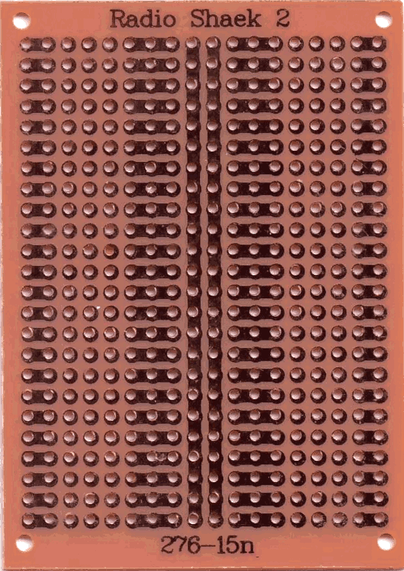
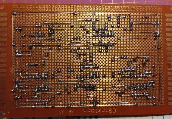
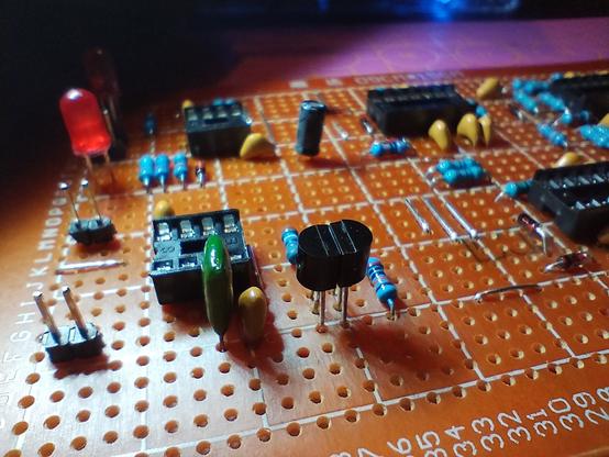
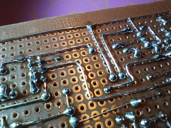
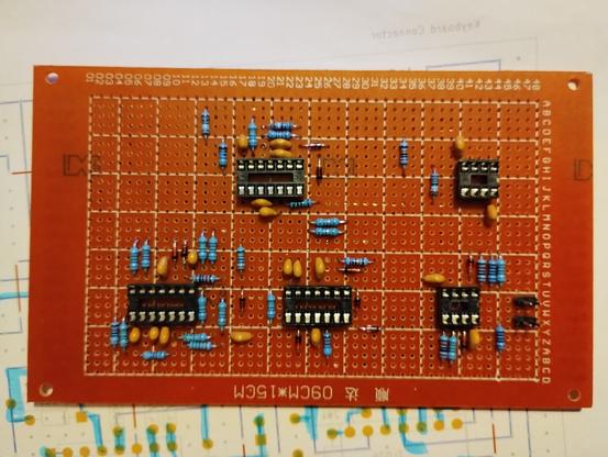
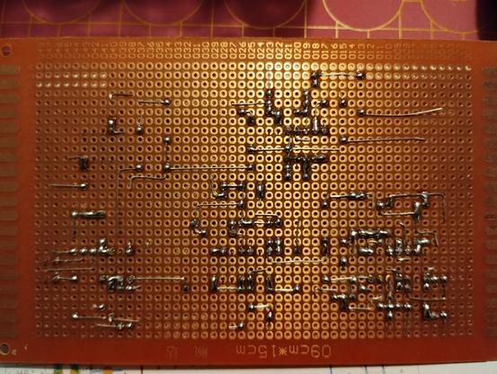
Some are #crap: laminated paper PCBs where the pads lift off the board if you even try to desolder something you added. Row/column labels missing, or (like I found with some recently) that don't line up between the front and back of the board 😆 , or most egregiously, they don't actually show the pad pattern on the front of the board, so you have to keep flipping it to check your parts are correctly placed. One example below.
I have some from "BusBoard Prototype Systems" that I like. The SB4 is a 38 x 24 (912 hole) board that is #snappable into quarters. Two of the quarters have rows that are 4-hole, 2-hole, 4-hole. The other two are 5 2-hole pads. Both types have a single bus running along each of the 2 long sides.
But ...
1/x
#electronics #hobby #ProtoBoard #PerfBoard #MatrixBoard #Chinesium
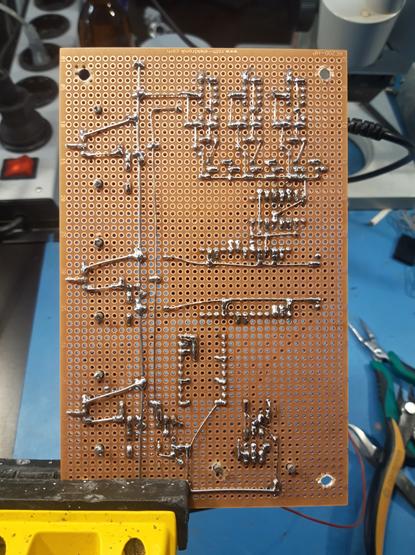
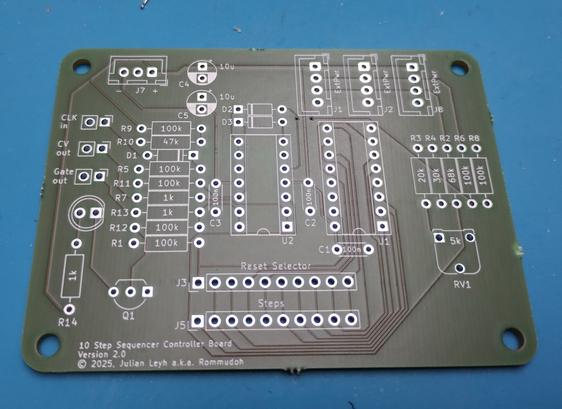
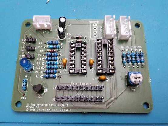
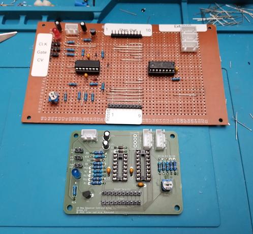
#soldered the second #PCB that arrived yesterday. This time it's #diysynth related. It's a drop-in replacement for my #perfboard 10 step #sequencer control board. It has identical connectors and was one more test of my PCB design skills and quality of @aislerhq manufacturing. It went really nice and works perfectly in place of the old one.
I only used a bottom ground plane and a different size for the board, so I'll have to redo it again for my final project.
#synthesizer #electronics
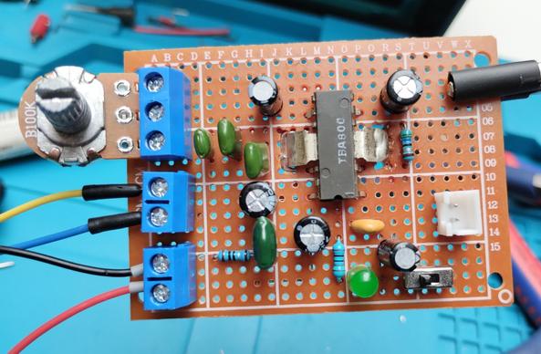
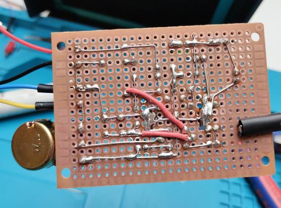
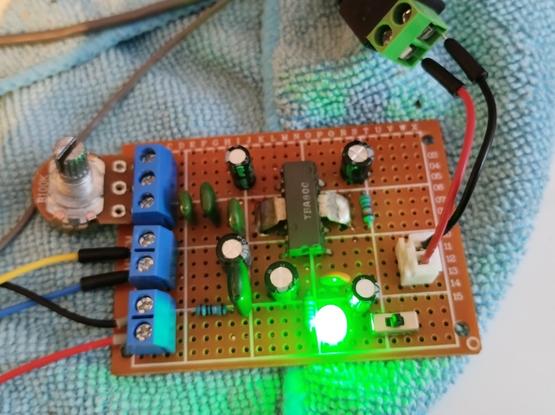
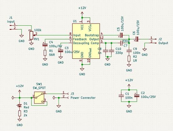
I had this old TBA800 IC lying around. So, I designed an audio amplifier circuit. It was fun to solded and works fine. It should support 5W at 16 Ohms load and 24V supply. I only tested it with 12V and 4 Ohms speaker.
The hardest part was soldering the tabs, since they act as heat sink, too.
I used #KiCad for the schematics and layout, although I had to create my own symbol and footprint for the IC. Also had to cut holes for the tabs into the #perfboard.
#electronics #AudioAmp #soldering #diy
A Simple Laser Harp MIDI Instrument https://hackaday.com/2024/06/19/a-simple-laser-harp-midi-instrument/ #MusicalHacks #wemosd1mini #laserharp #perfboard #lasercut #ESP32 #midi #ldr
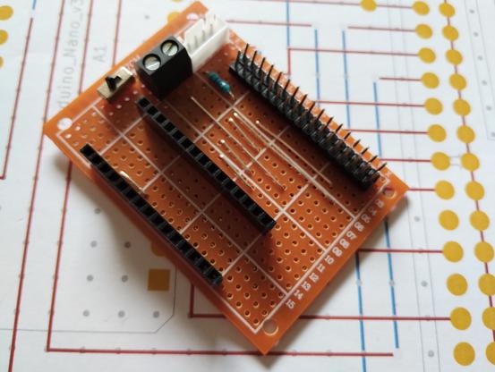
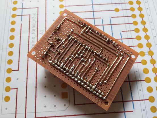
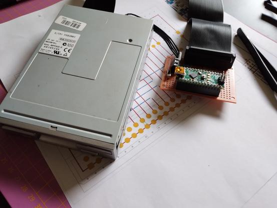
Finished building the DrawBridge.
It seems to work, but I need to connect an external 5V power supply, since my laptop doesn't provide enough voltage to power the drive.
Also, this #floppy drive was old, and makes squeaky noises when trying to write. The inserted floppy shows scratch markings, too.
So, I'll need a proper floppy drive.
#Amiga #floppydrive #soldering #perfboard #ArduinoNano #Arduino
Before designing a PCB, I find it always helps to first produce a solid prototype. In this case using a mixture of stripboard and wire-wrap construction methods.
#Stripboard #Veroboard #Perfboard #Electronics #Maker
[17/04/2020]
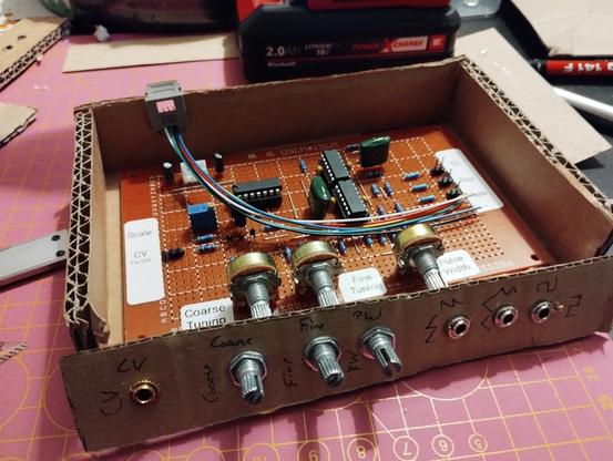
Planning on creating an #enclosure for my #diysynth #perfboard modules.
I'll use 5mm transparent #polystyrene for the body, and 2mm #aluminium for the front panel.
Here is a crude #prototype done in #cardboard.
I'll have to unsolder the #potentiometers and #LEDs to place them on the panel. The audio jacks will be connected to the pin headers.
#modular #synthesizer #crafting
After fixing it, I decided to test it. It is connected in place of the step sequencer. It seems to have a small issue with triggering, sometimes causing the sample and hold to resample when releasing the key. Have to look into this.
Here is a short demo of me pressing some buttons: https://makertube.net/w/g88KJst76crKDDJeDxx4QN
#diysynth #synthesizer #perfboard
Demo of my Keyboard input
https://makertube.net/videos/watch/7a78109a-cede-4ddf-87ec-bcf81a9b47a2
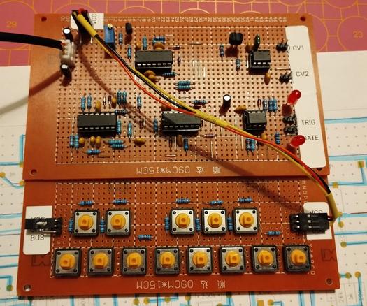
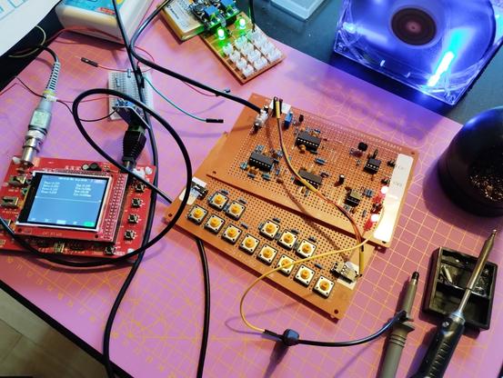
Finished #soldering the #perfboard yesterday. Sadly, it didn't work as intended. Now comes the fun part — analyzing and fault finding. Already fixed one of the issues by replacing a #capacitor with a bigger one. Now the trigger and gate are generated correctly, but the output buffer for them are constantly high. The sample and hold for the CV outputs worked from the beginning.
#diysynth #keyboard #OpAmps
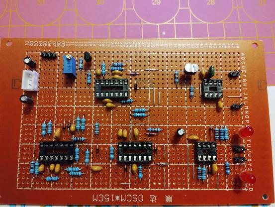
More #soldering done. All components are placed now, only have to do a few connections and jumper wires. I really notice how I'm improving.
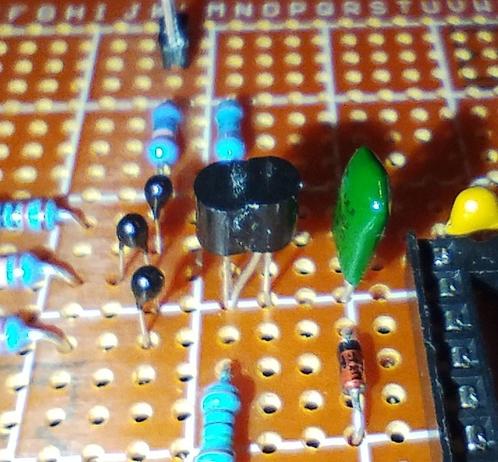
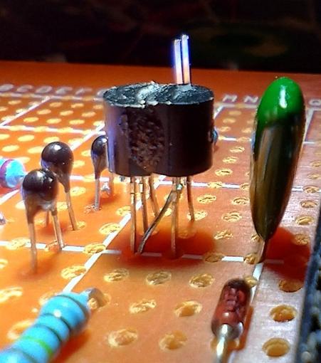
Also, the return of the dancing #transistors, this time two #JFET.
#diysynth #perfboard #dancingtransistors
Today's #soldering progress on my single buss 1V/oct keyboard, the controller part. Only missing the electrolytic and poly capacitors, some wiring and connectors.
Schematics from #MFOS:
https://musicfromouterspace.com/analogsynth_new/SINGLEBUSSKEYBOARD2007/SINGLEBUSSKEYBOARD2007.php
I did the key part for one octave previously, and modified the schematic for the parts I have available. The key part will be chainable, so I can add more octaves if everything works fine.
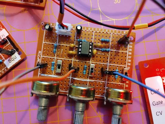
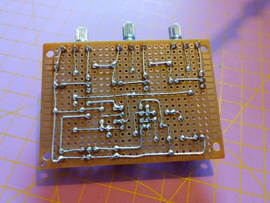
Today's #soldering project done: a #mixer with three inputs using a #TL072 #opamp. I have a layout planned for a slightly bigger #perfboard with four to six inputs.
#diysynth
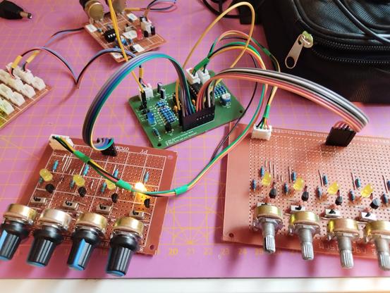
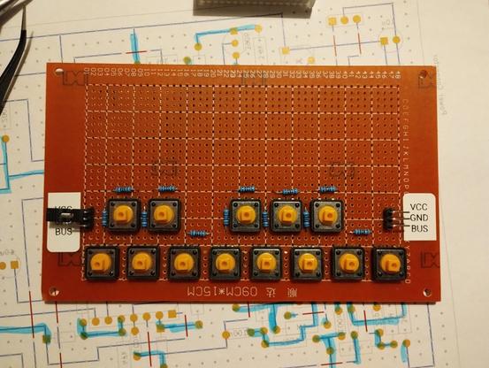
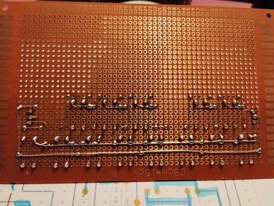
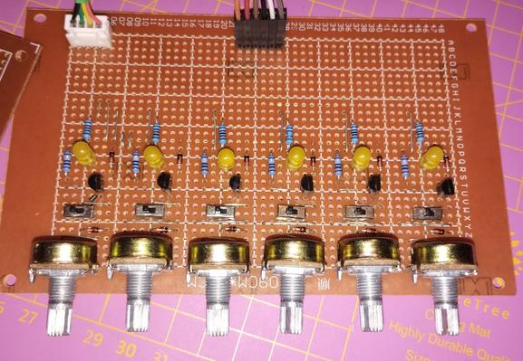
Today's #soldering project: six step expansion #perfboard for the #sequencer - now I can make use of all 10 steps.
One of the switches was defective and I had to replace it after soldering.
#electronics #diysynth
@mixal
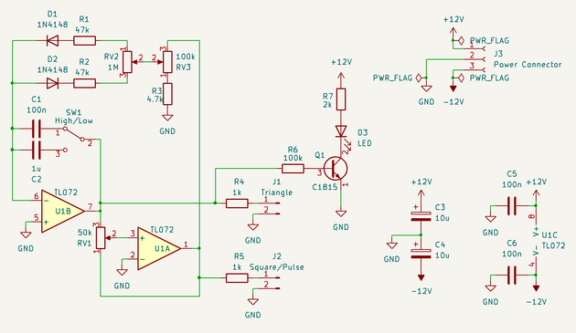
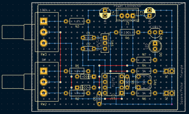
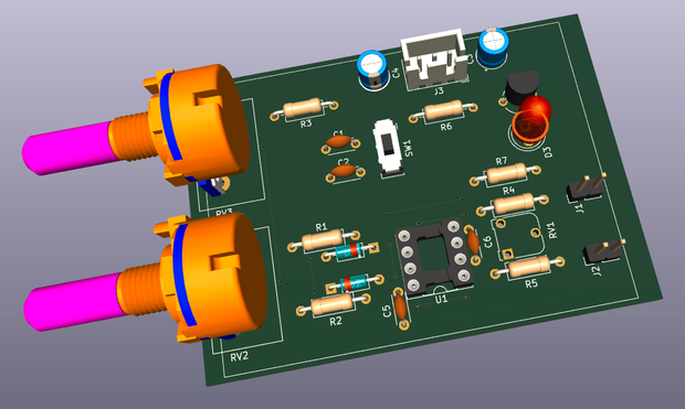
Here is the #schematics done in #KiCad, as well as the "PCB" layout used for the #perfboard and the 3D rendering.
I chose 1µF and 100nF for the caps, smaller being the faster one.
It was inspired heavily by the design of SoundBender found here: https://soundbender36.wordpress.com/2019/12/28/36-synthetiseur-modulaire-diy-dual-lfo/
#diysynth
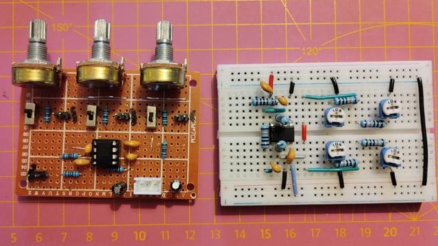
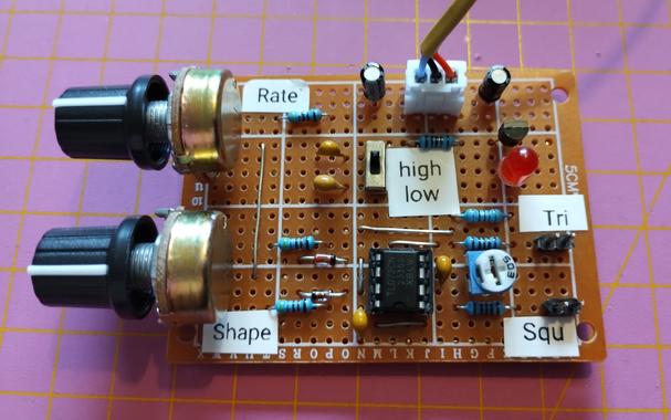
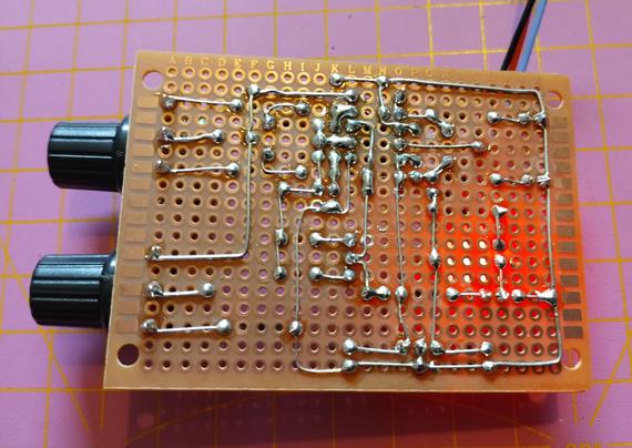
The last module of my #diysynth that I had on breadboard is now soldered to a #perfboard. It's a #LFO with triangle and square wave output, with shape #potentiometer that changes the triangle wave towards sawtooth or ramp, and the duty cycle of the square wave between 5% and 95%.
It has two speed settings with 0.12 to 5.3 Hz, or 1/80th to 0.5 Hz frequency. I might build a second one with different capacitors for higher frequencies.
#soldering #synthesizer #oscillator #electronics
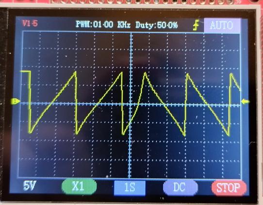
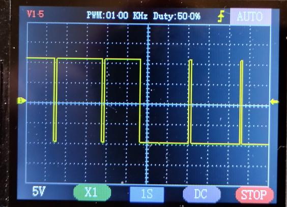
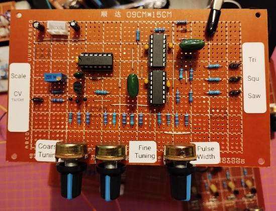
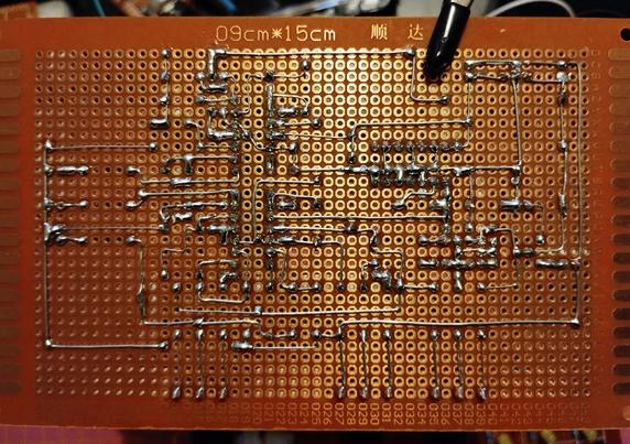
Finished #soldering my #VCO #perfboard. It is calibrated to 1V/Octave and outputs sawtooth, square/pulse, and triangle waveforms.
The heart is a #CD40106, using only one of the inverted Schmitt triggers. I tried adding more, but couldn't fit them properly. Maybe if I left out the triangle wave output, which would remove the upper #TL074.
My power supply board is getting full, I should add a few more sockets.
Demo video: https://makertube.net/w/bxShHoDY5cCP7krbjnFgh8
#diysynth #waveform
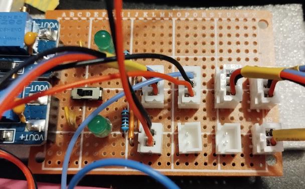
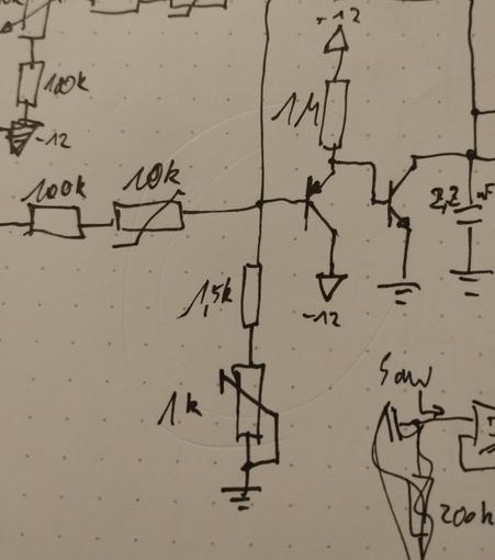
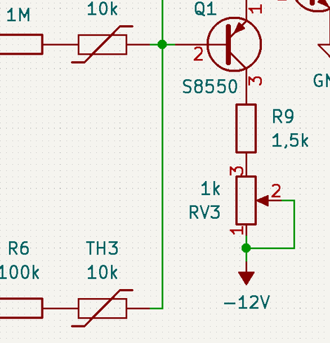
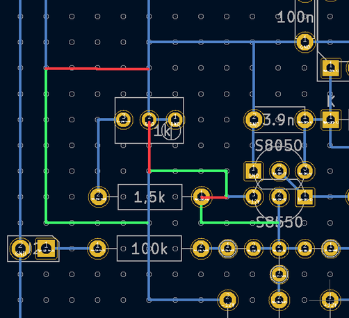
oh no! how could this happen... I made a mistake when transferring my hand-drawn #schematics into #KiCad. Needless to say, the circuit doesn't work as intended.
Thankfully, it only affects a sparsly populated area on the #perfboard and I can fix it by cutting two wires and doing a bit of re-routing. doesn't even require a jumper wire.
#soldering #electronics
I call them the #dancing #transistor pair... #superglued together and middle leg of one crosses into the hole of a side leg of the other one.
#electronics #perfboard #soldering
