#mcHF

Piotr Esden-Tempskiesden@chaos.social
2024-12-17

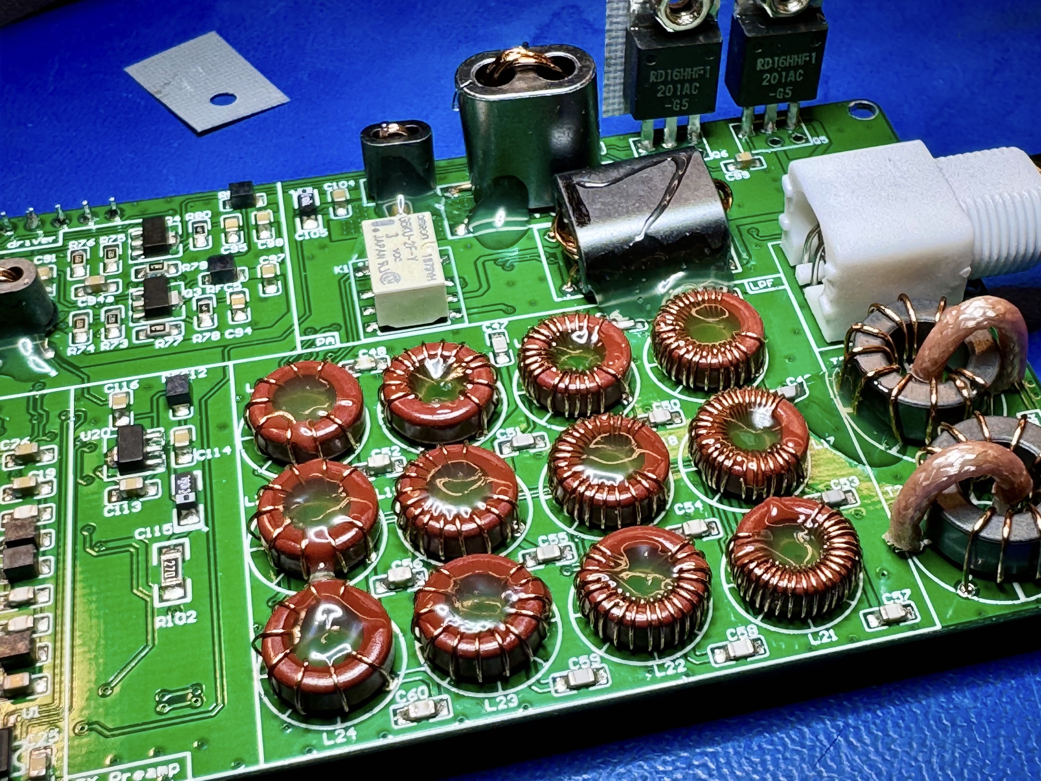
While I had the radio open, I also decided to decrease the rattle and tack down the inductors using some hot glue. I am aware it is getting warm inside the radio so that might just create a huge mess, but I feel it is worth a try. If that does not work out I will remove it (it should be relatively easy using IPA) and replace it with silicone. We will see™️ :D #hamradio #kitradio #mchf

The mcHF RF board. The Toroid inductors have a big blob of hot glue melted into the center hole. The glue goes all the way down to the PCB keeping them in place. On the right the SWR/Power meter inductors have also a small dab of hot glue on the side. In the background the transformers also have some hot glue to keep them in place.
Piotr Esden-Tempskiesden@chaos.social
2024-12-16

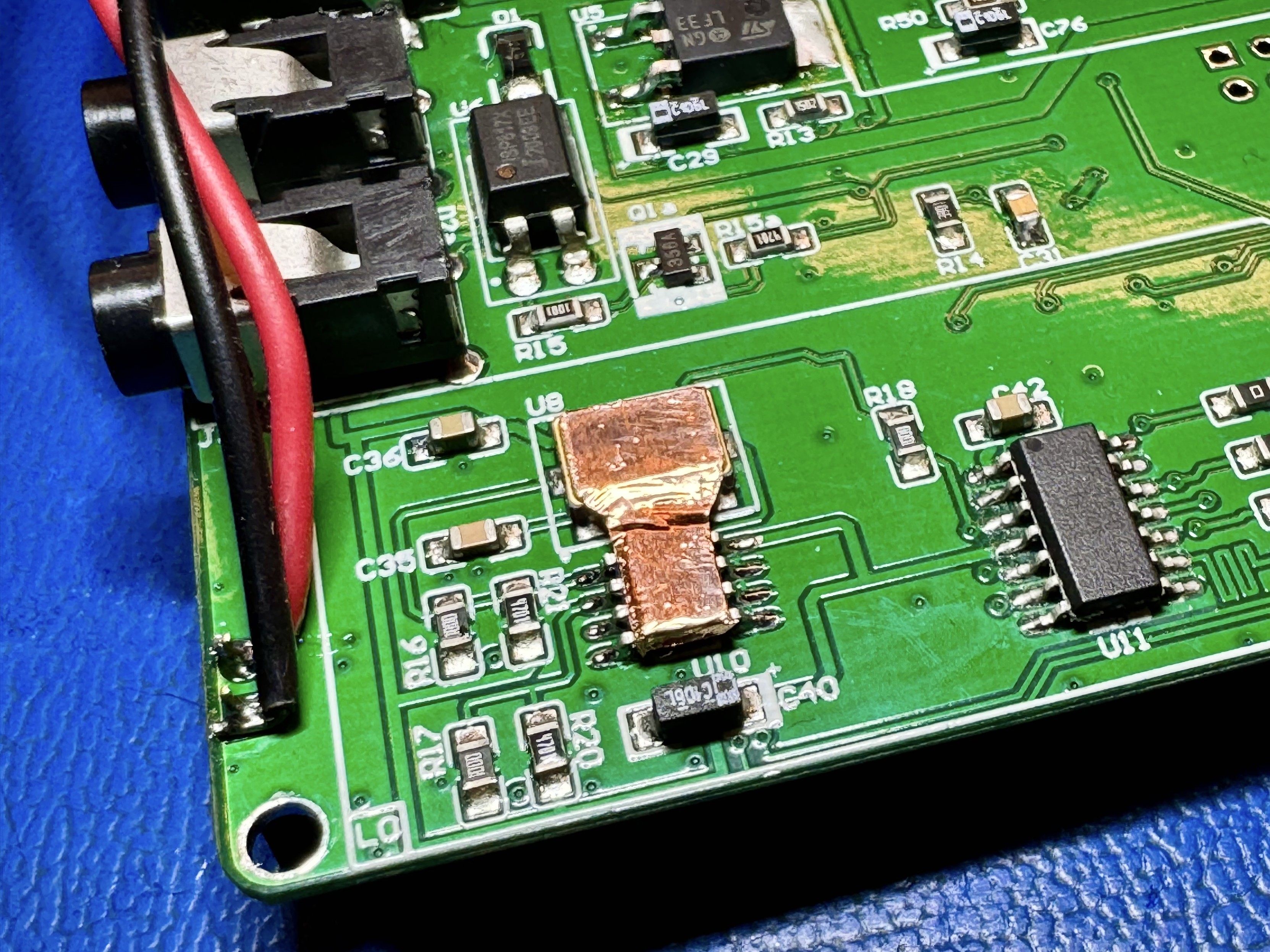
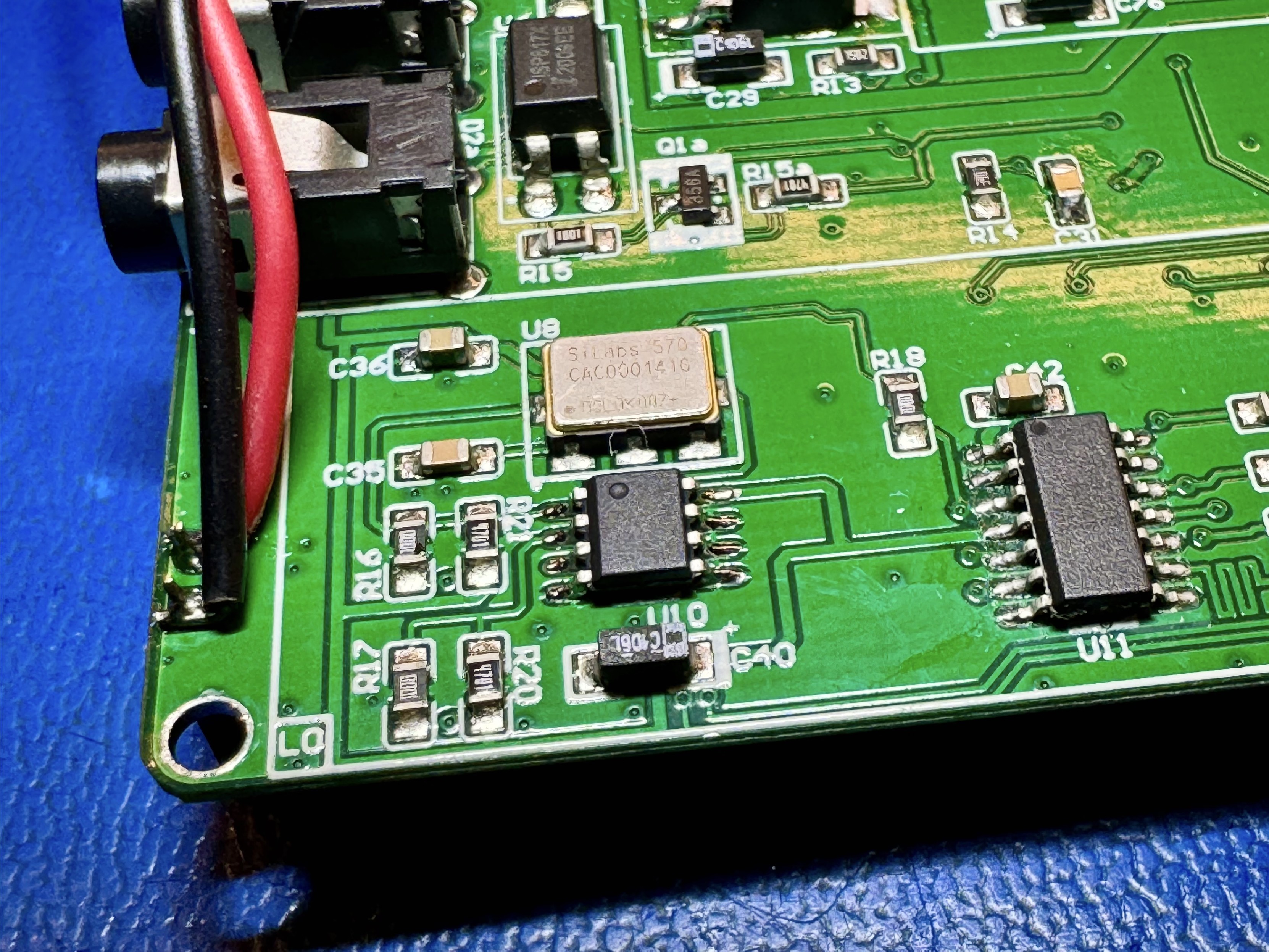
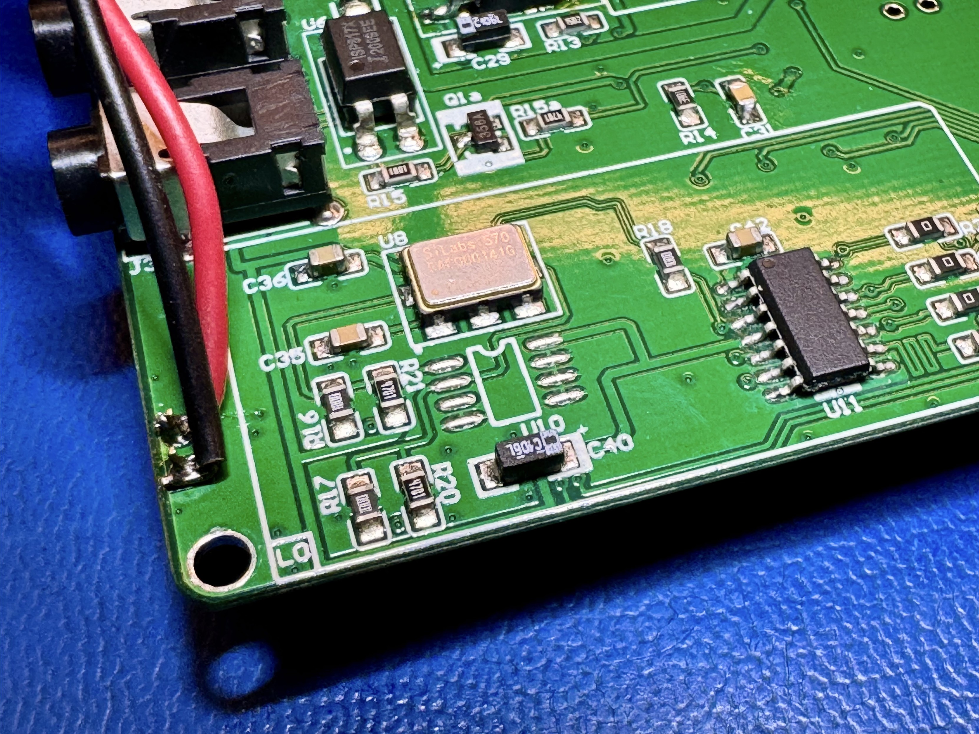
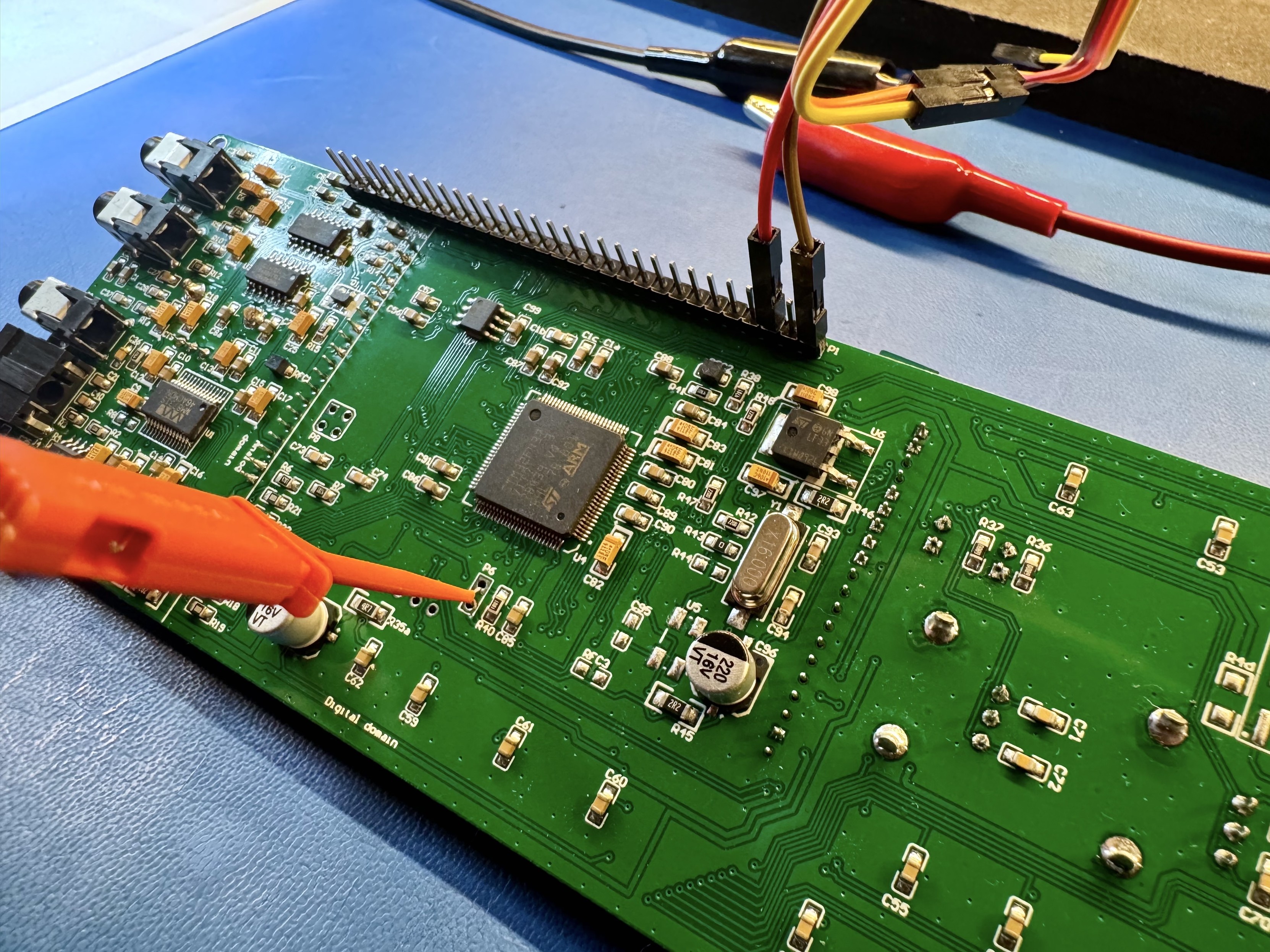
Another little thing to do on the radio: I now got some silicone thermal pads for the TO-220s, so I have to take the radio apart and put them in. While I am at it I am also adding the optional TCXO temperature sensor. The instructions recommend to couple the oscillator and the sensor with some copper tape. #hamradio #kitradio #mchf

The mcHF RF board with an SO-8 Temperature sensor soldered on. There is a copper tape shape bridging across from the SO-8 To the square oscillator package.The same mcHF RF board but without the copper tape connecting the thermal sensor with the TCXOThe mcHF RF board before the temperature sensor was soldered in. The SO8 package is missing.
Piotr Esden-Tempskiesden@chaos.social
2024-12-09

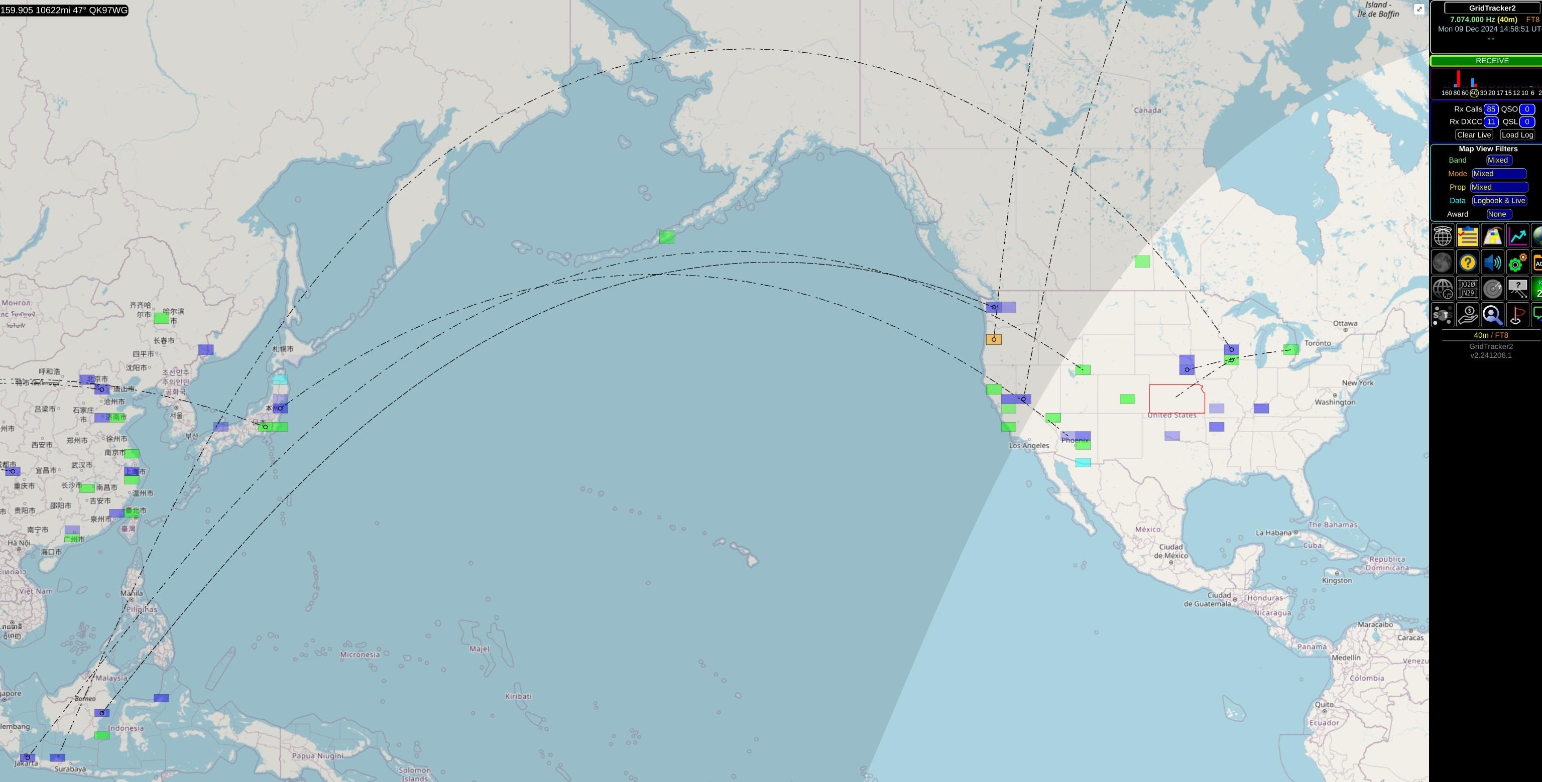
Digital modes like FT8 are quite amazing! I am able to receive messages from across the globe! (Also: Setting this up was shockingly easy with the mcHF. All I needed to do was to hook it up over USB and configure the WSJT-X software to use it!) #hamradio #mchf #ft8 #digital

Screenshot of the GridTracker software showing FT8 communication log. Some blue and green squares in the us as well as China and Japan!
Piotr Esden-Tempskiesden@chaos.social
2024-12-09

I have to wait for a dummy load and a few other bits and bobs to arrive before I can calibrate the radio and try to go on air with it. In the mean time I am trying to get familiar with the controls and while doing that I managed to receive some SSB on 40m! 🎉📻 #hamradio #kitradio #mchf

Piotr Esden-Tempskiesden@chaos.social
2024-12-08

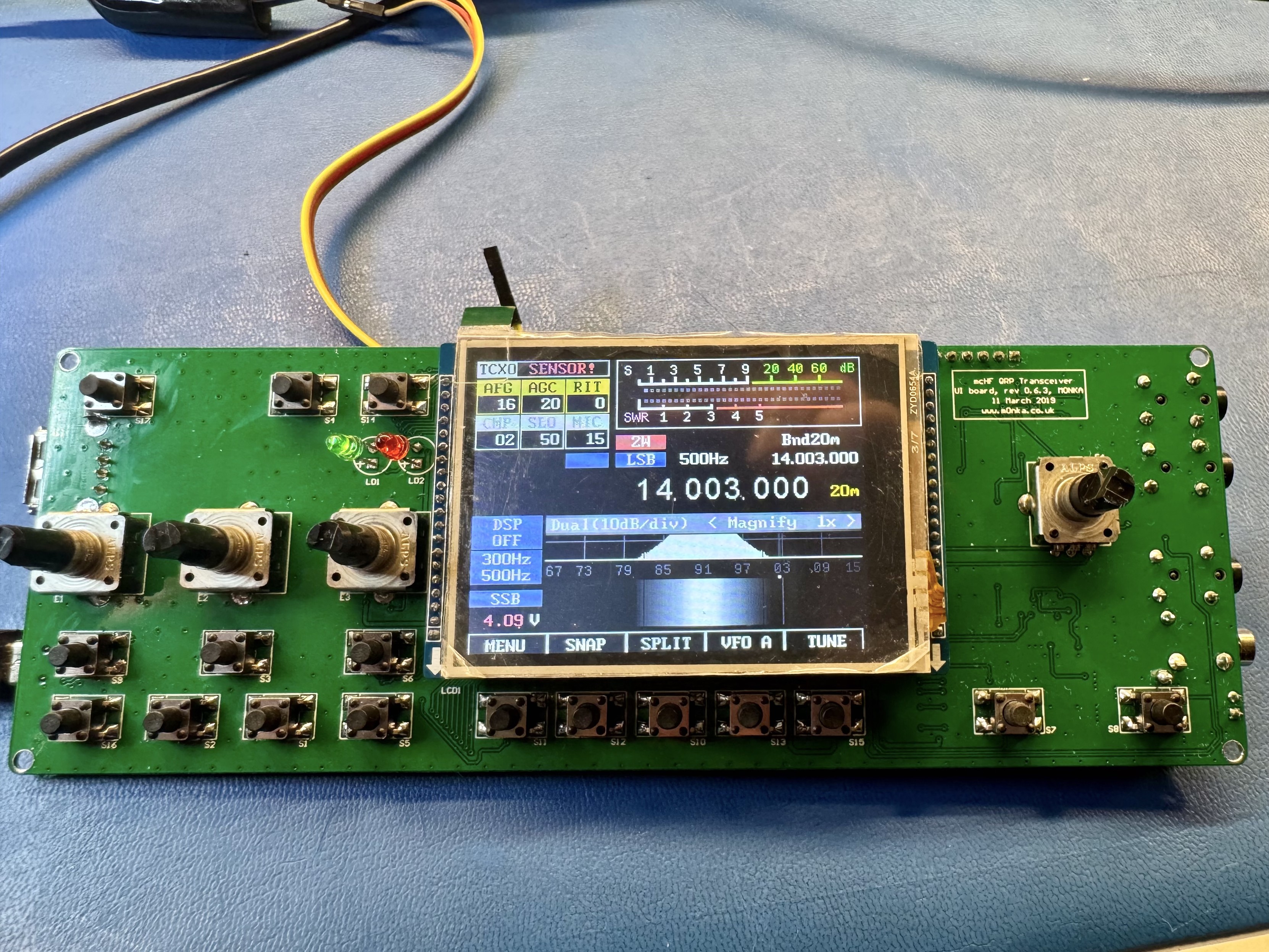
And here we go! We have a fully assembled mcHF QRP radio! There is more work to do, but let's sit back and enjoy the view l for a little bit! :D #hamradio #kitradio #mchf

The mcHF QRP radio fully assembled in it’s enclosure.
Piotr Esden-Tempskiesden@chaos.social
2024-12-08

The front panel has some silicone covers for the buttons. But oddly enough these are not mats that fit the hole pattern. One has to clip the buttons apart and then insert into the button holes. It makes the assembly a bit awkward because the buttons love to fly out of position. #hamradio #kitradio #mchf

The front of the mcHF enclosure in the background. In the foreground there are scissors holding two silicone buttons in a strip.
Piotr Esden-Tempskiesden@chaos.social
2024-12-08

Now the UI board can be mounted on top of that. Let's finally remove that pesky protective film from the LCD display! #hamradio #kitradio #mchf

Piotr Esden-Tempskiesden@chaos.social
2024-12-08

Next is the RF board we spent so much time on, followed by an RF shield. The enclosure comes with an RF shield but it needs a bunch of modifications. So instead of doing that I designed my own RF shield and ordered it from Send Cut Send! It worked out great. You can find the design on my GitHub. ;) github.com/esden/mchf-rf-shiel #hamradio #kitradio #mchf

The mcHF radio enclosure with the RF board installed. On top of the RF board is a piece of sheet metal with multiple cutouts for components. This is the RF shield to decrease the amount of interference from the UI board coupled into the RF board.
Piotr Esden-Tempskiesden@chaos.social
2024-12-08

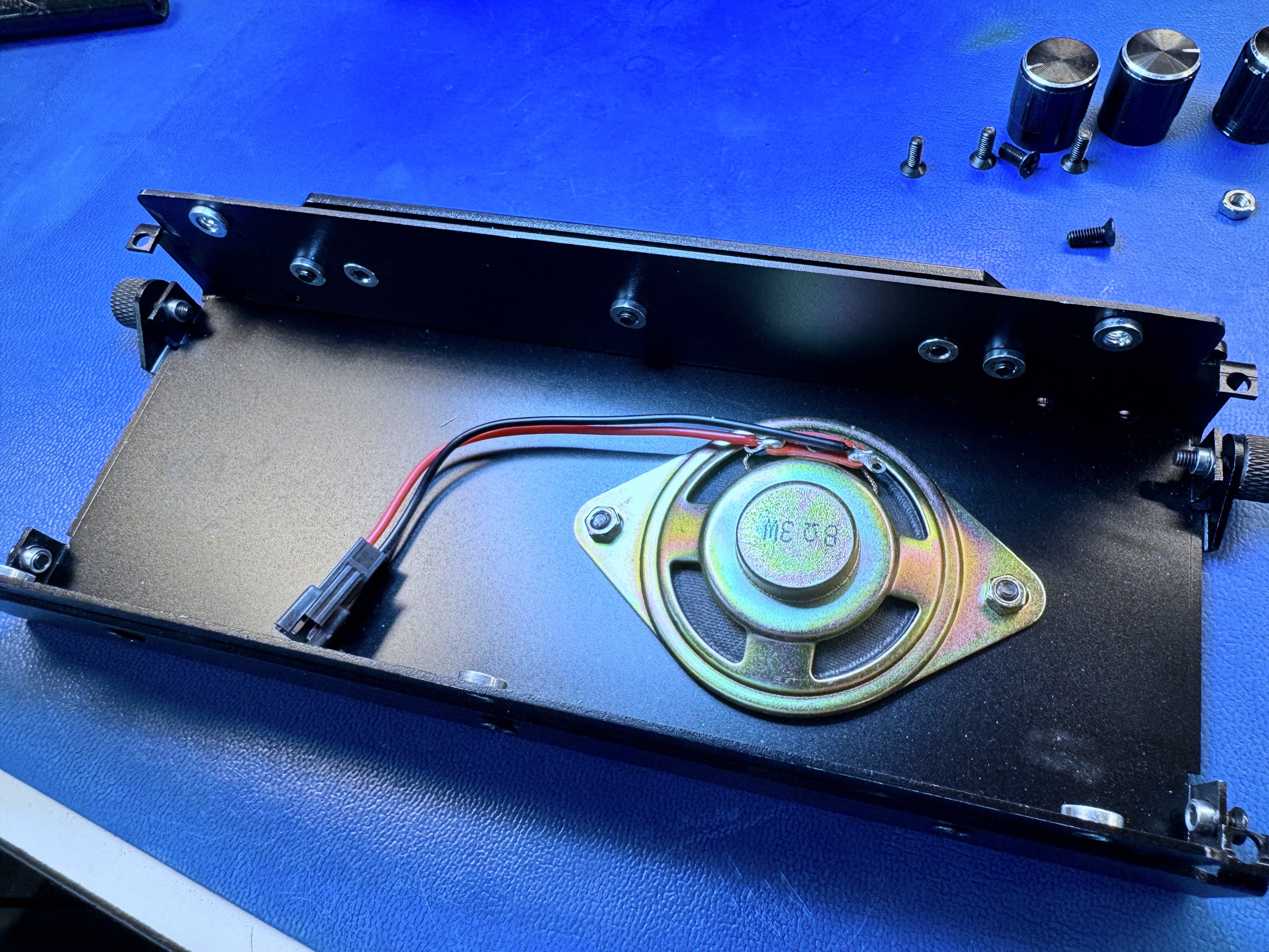
First thing for the case is to screw in and solder the wire to the speaker. #hamradio #kitradio #mchf

Speaker screwed into the back half of the mcHF radio enclosure. The speaker has a red and black lead with a connector soldered to it.
Piotr Esden-Tempskiesden@chaos.social
2024-12-08

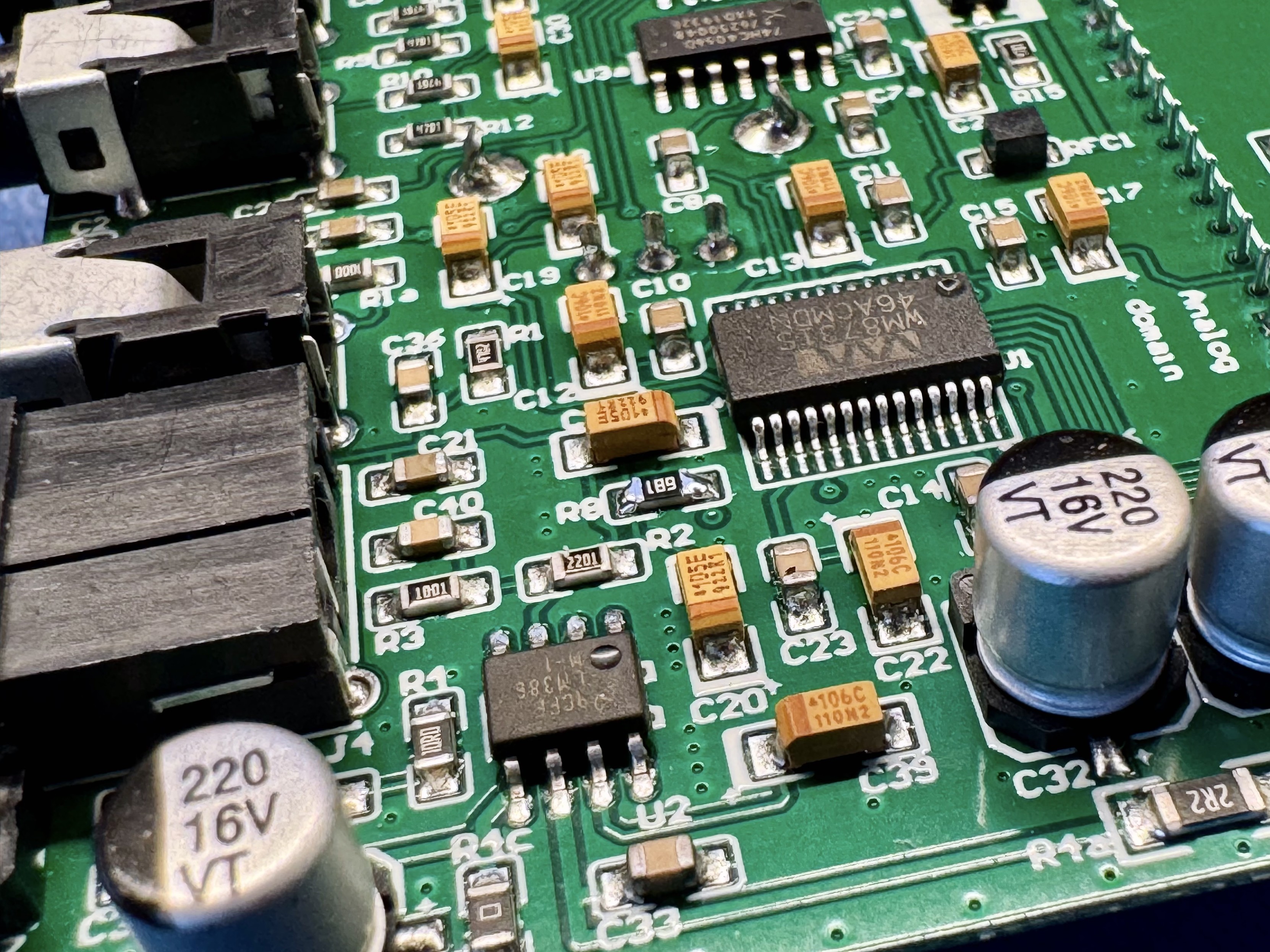
Remember how at the beginning we were missing a resistor for the electret microphone? It arrived, so let's solder it in before we assemble the whole radio into the enclosure. #hamradio #kitradio #mchf

The mcHF UI board with the R8 resistor soldered in. This provides phantom power to the electret microphone of the handset.
Piotr Esden-Tempskiesden@chaos.social
2024-12-08

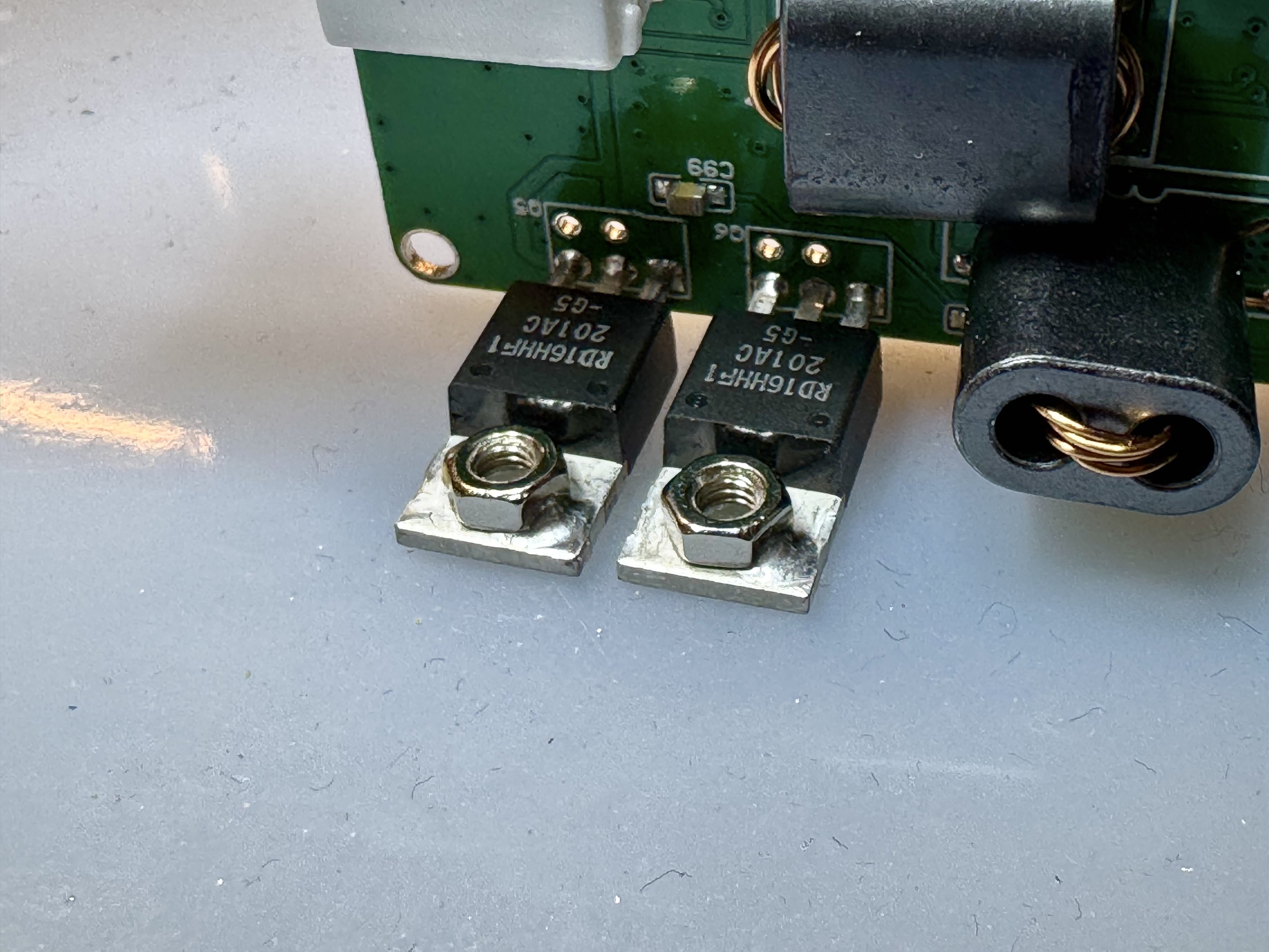
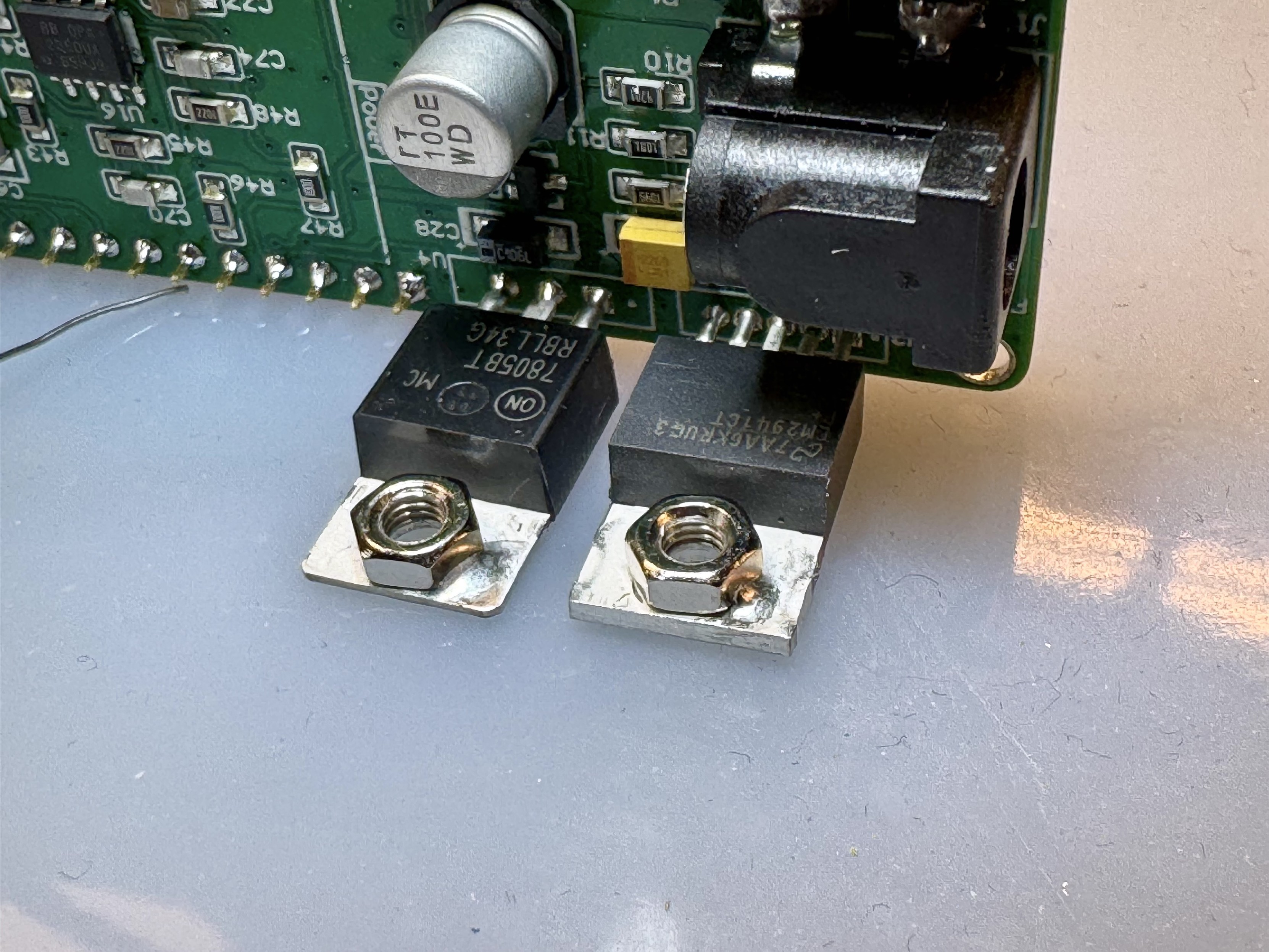
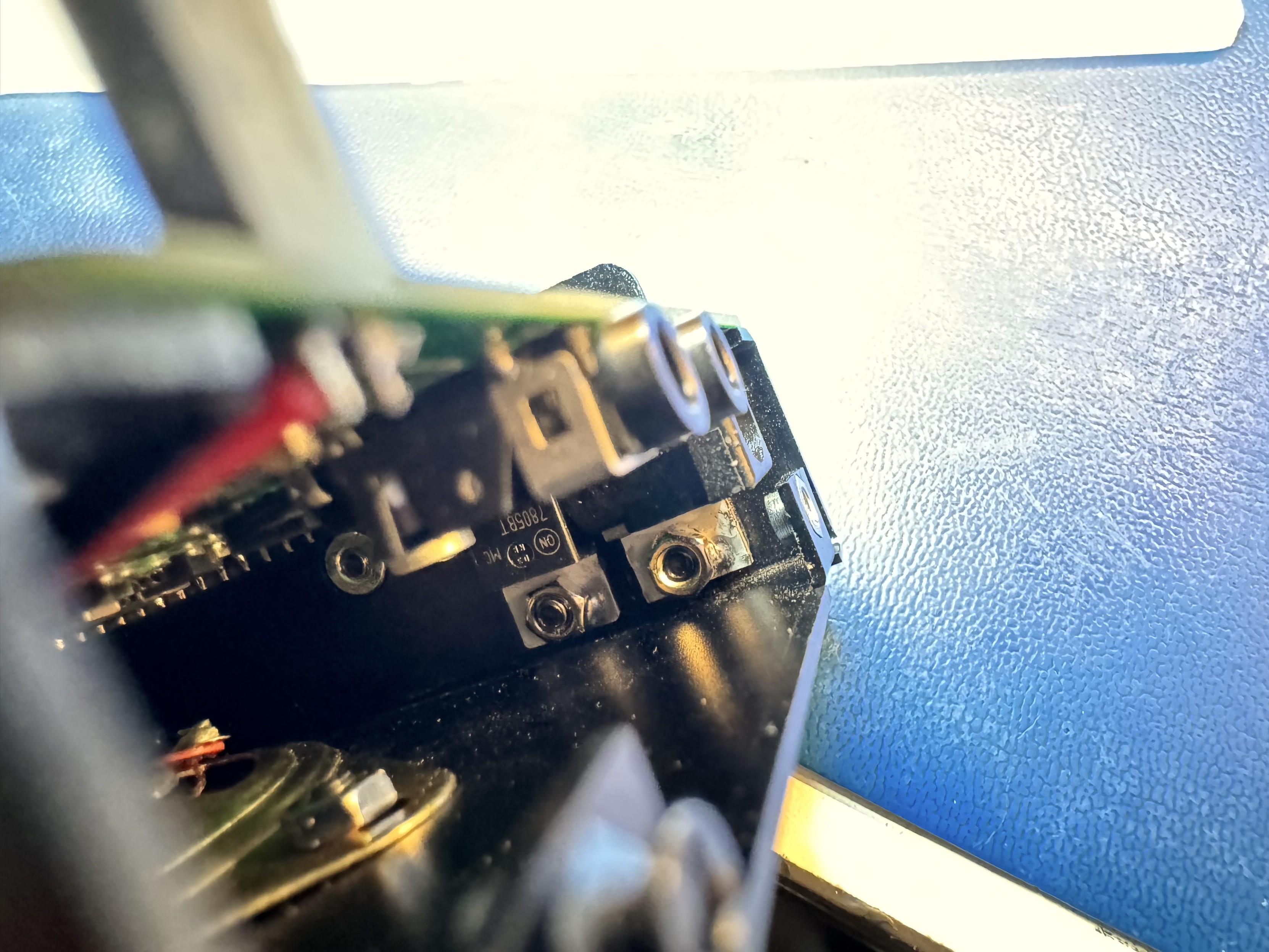
To install the TO-220 PA MOSFETs and LDOs it is necessary to partially assemble the RF board into the case. It is really hard to get the nuts onto the chassis bolts so I decided to solder them onto the tabs. (these are the moments I praise having a JBC iron!) #hamradio #kitradio #mchf

The two Power Amplifier (PA) MOSFETs in TO-220 packages. There are screw nuts on the thermal pads that have a dab of solder in the corner keeping them in place. The components are already soldered into the RF PCB.The two through hole voltage regulators. There are screw nuts on the thermal pads that have a dab of solder in the corner keeping them in place. The components are already soldered into the RF PCB.The voltage regulators installed in the radio enclosure. Showing that it is a very tight space making the installation of the screw nuts difficult.
Piotr Esden-Tempskiesden@chaos.social
2024-12-08

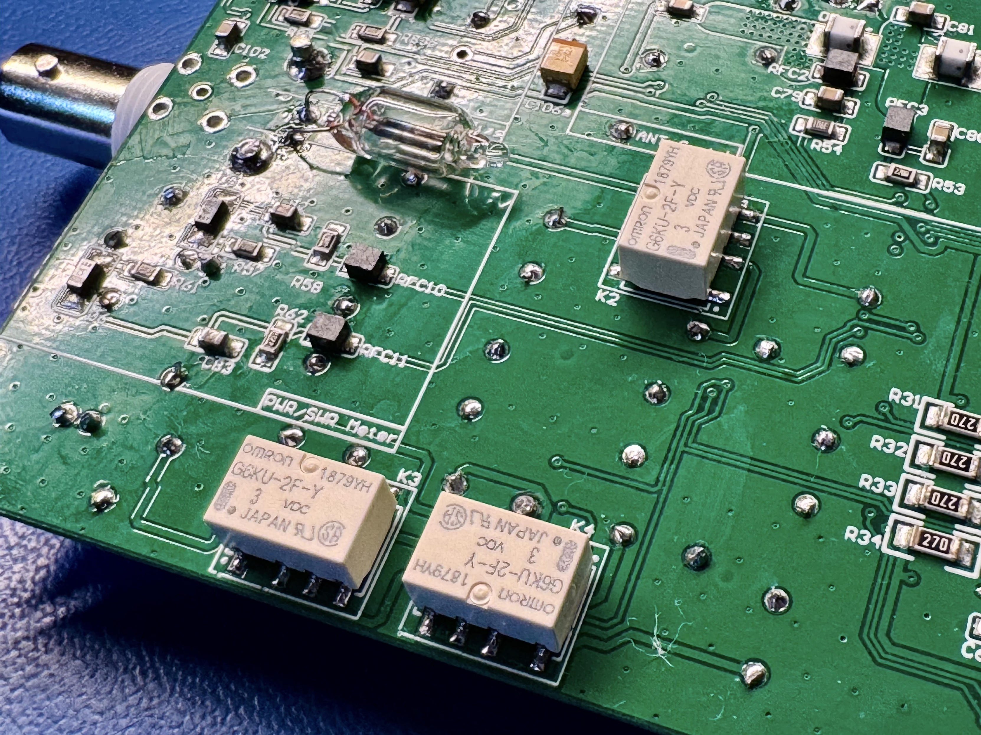
After mounting one stray relay on the back side of the board, we can finally assemble the parts that go onto the "front side" of the RF board. Another funky balun, 3 relays, some connectors and a neon bulb to protect from the antenna zapping us. :D ⚡️ #hamradio #kitradio #mchf

The mcHF RF board. Three white boxes which are the micro relays as well as a glass bulb with two electrodes inside. The bulb is a neon bulb connected to the antenna.mcHF RF PCB back still visible are all the magnetics, but now it also has a relay mounted.Full view of the front of the mcHF RF board. With the connectors, relays, neon bulb and the balun installed.
Piotr Esden-Tempskiesden@chaos.social
2024-12-08

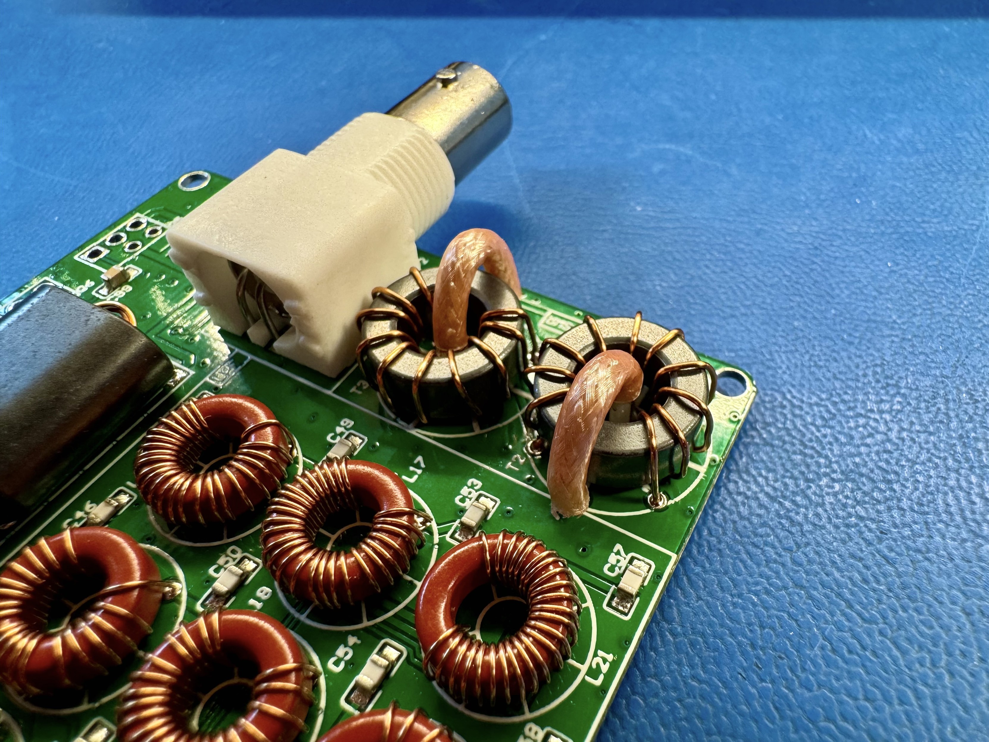
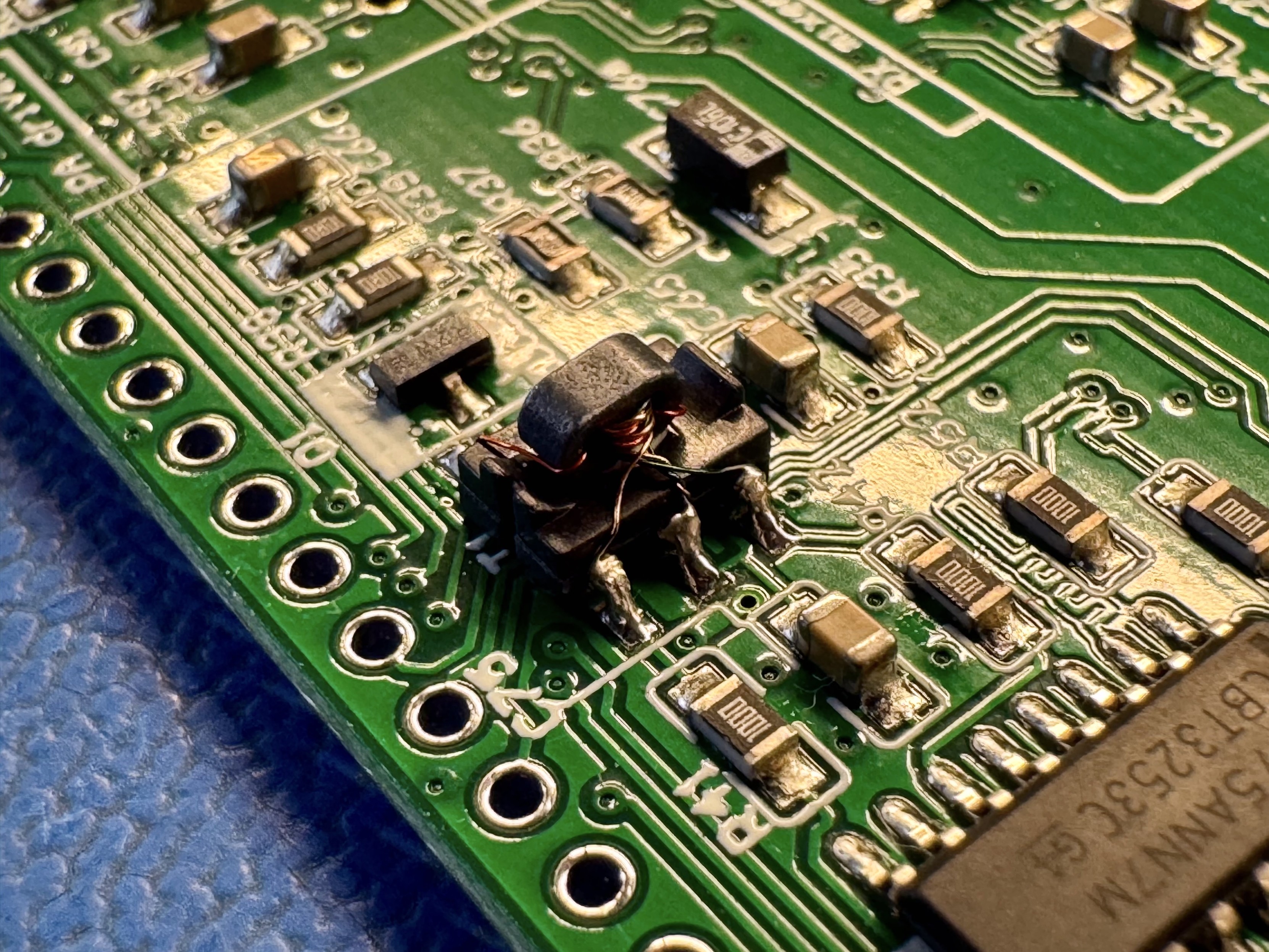
Last hand built items on the RF board are the SWR/PWR meter transformers. I have to admit, getting those coax windings was a major pain in the back side… I am pretty sure the bend radius is “illegal”. I have the feeling that the board was not originally designed with those coax windings in mind. But as far as I can tell things are soldered and connected where they should and the two toroids are wound in their opposite directions as the documentation describes! 😅 #hamradio #kitradio #mchf

The mcHF RF board with a bunch of magnetics and the BNC connector mounted. The newly added items are  two square cross section toroids with 10 enameled wire windings each. The toroids also have one winding of a coaxial cable each. The coax provides “Faraday shielding” to provide adequate reverse isolation for the transformer.
Piotr Esden-Tempskiesden@chaos.social
2024-12-07

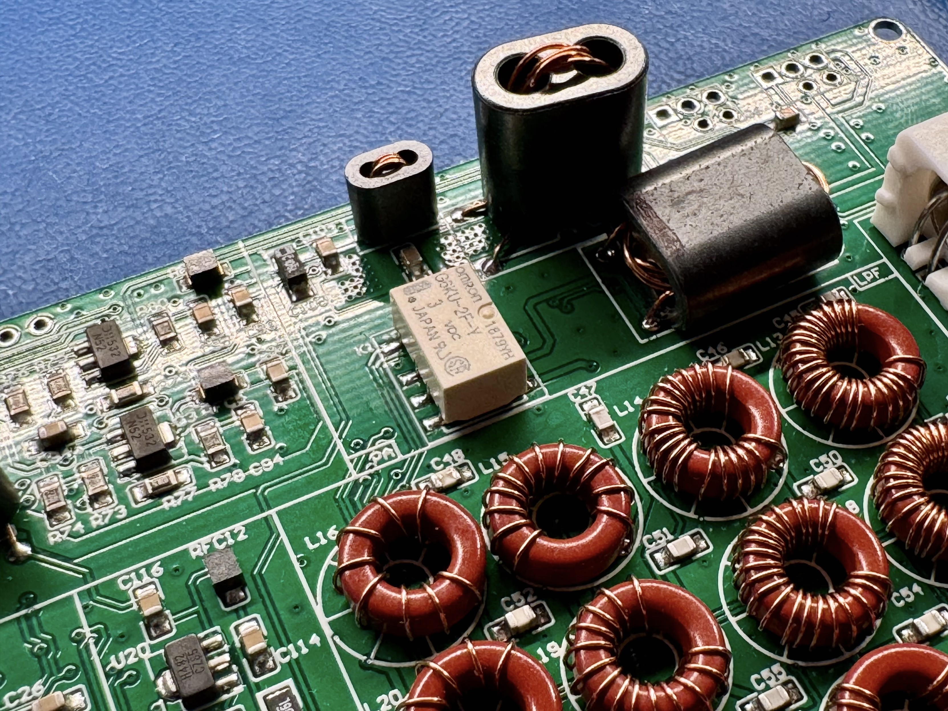
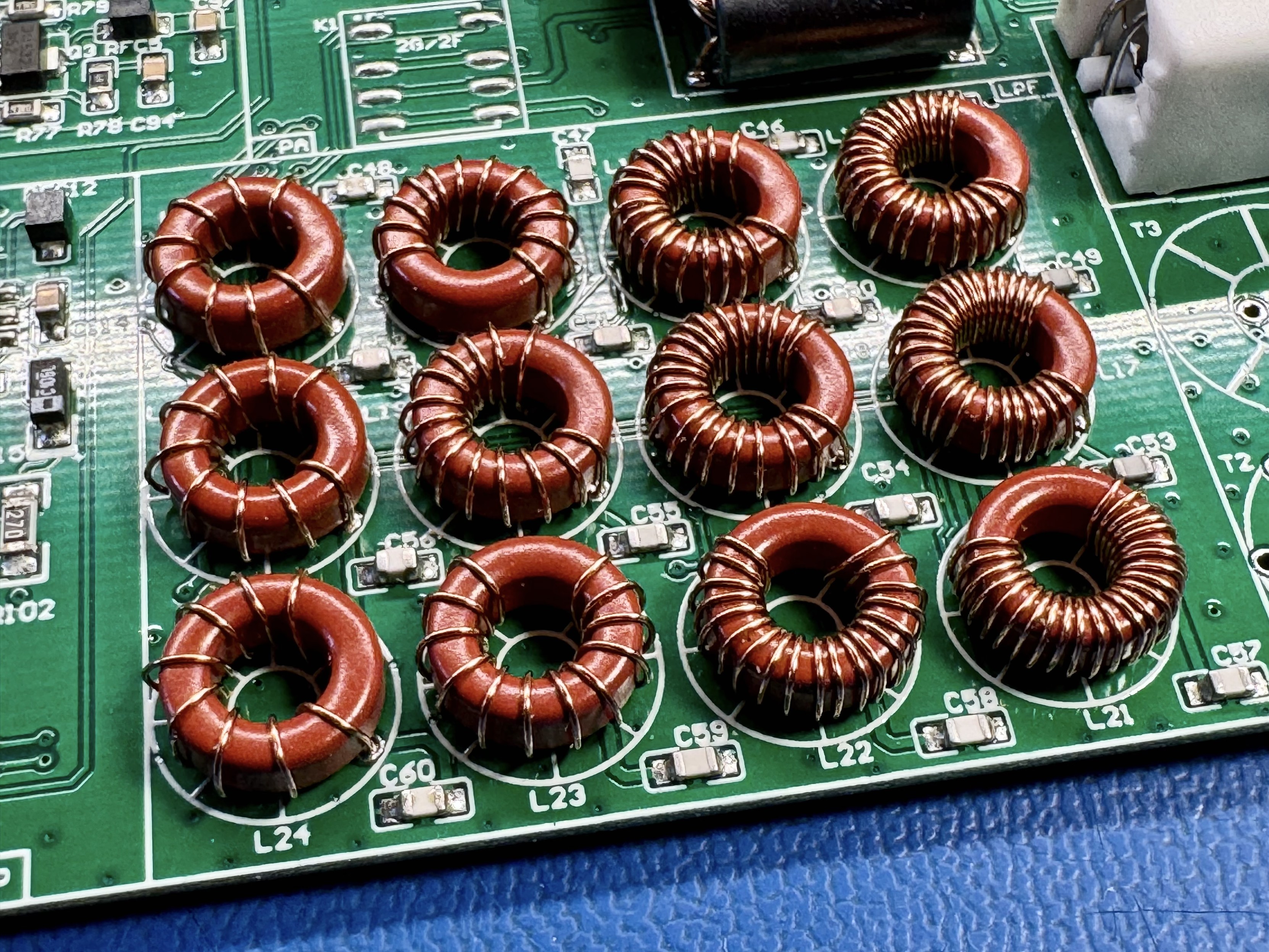
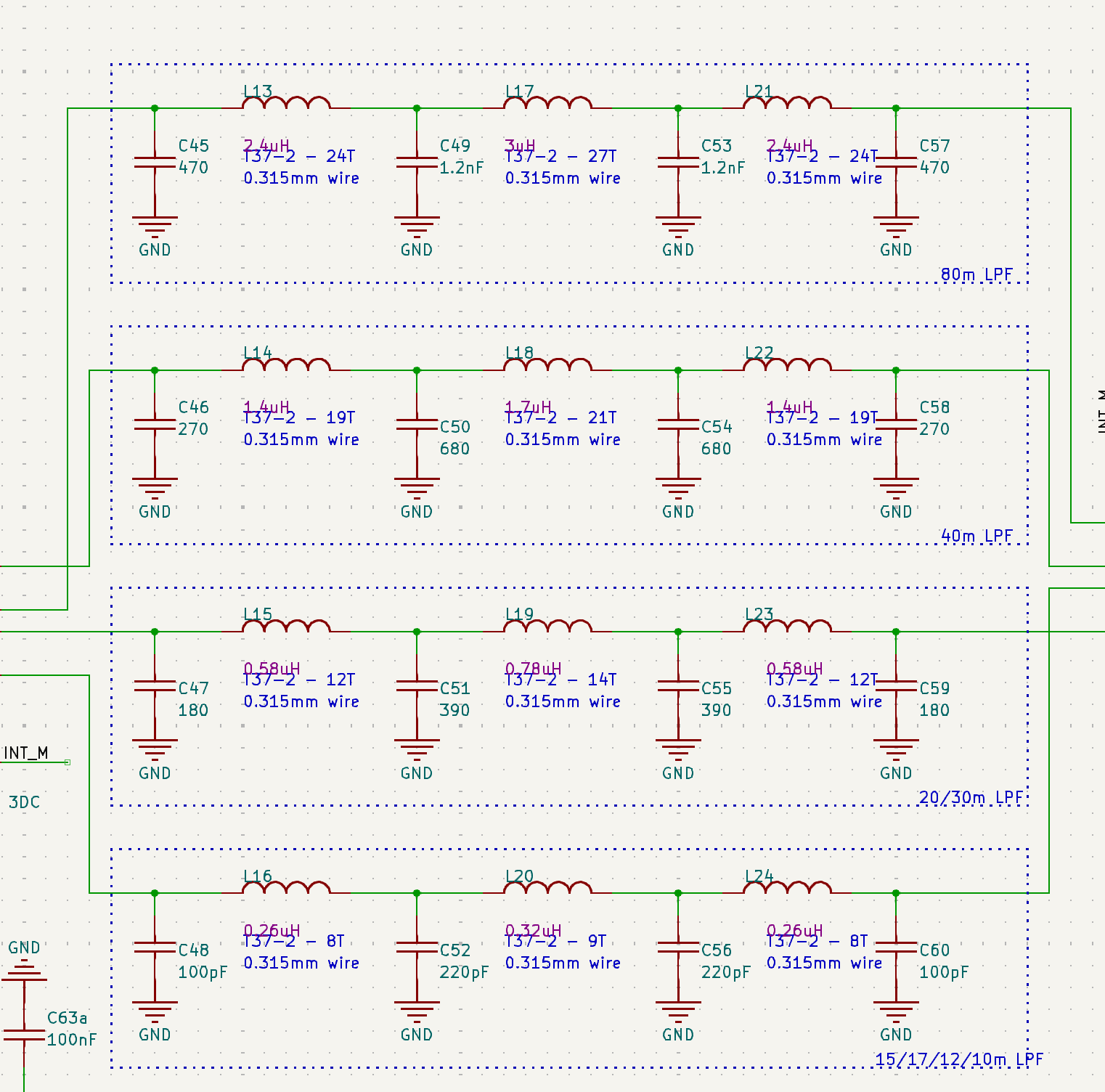
Here we go! All the filter inductors are wound and soldered in! I tried my best to do an even and clean job... I did check them with the low cost LCR meter I have and they seem to be in the ballpark of the specified values. #hamradio #kitradio #mchf

The mcHF RF pub with 12 toroidal inductors. The winding count varies from left to right. On the left the inductors have less windings than on the right. The left most set of three inductors are for the roughly 10m bands, then 20m and 30m. The last two columns are 40m and 80m bands.
Piotr Esden-Tempskiesden@chaos.social
2024-12-07

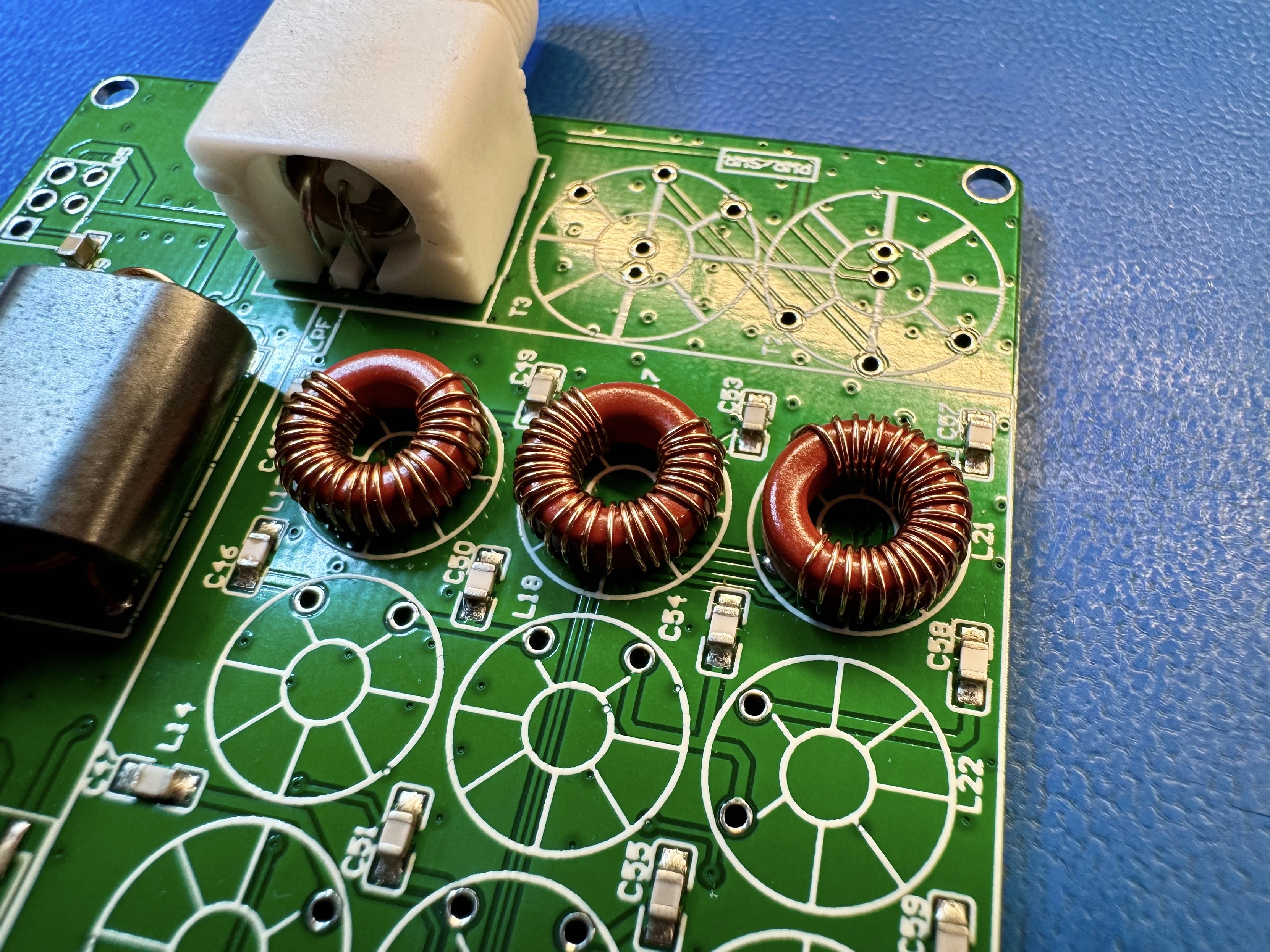
Now I need to wind all the inductors for the Lowpass filters. Each filter consists of 3 inductors. I started with the 80m band toroids. 24, 27 and 24 turns each. #hamradio #kitradio #mchf #kicad

The green mcHF RF PCB. In the center there are three red ferrite toroids with copper enameled wire wound around them. From left to right they have 24, 27 and 24 windings each.Schematic of the mcHF filter circuit. There are four groups of filters. For 80m, 40m, 20/30m and 15/17/12/10m bands. Each group of filters is a series of three inductors with capacitors connected to ground between each stage.
Piotr Esden-Tempskiesden@chaos.social
2024-12-06

As a side-quest. To make my life a bit easier. I have taken the mcHF design files and imported them to KiCad. You can find them on my GitHub. github.com/esden/mchf-kicad and yes they open in KiCanvas!!! ;) UI Board: kicanvas.org/?github=https://g RF Board: kicanvas.org/?github=https://g #hamradio #kitradio #mchf #kicad

The mcHF power amplifier section schematic as viewed in KiCanvas.
Piotr Esden-Tempskiesden@chaos.social
2024-12-06

I have mounted the first few hand wound devices on the board. A balun, a choke and two transformers. They are part of the power amplifier circuit. (still getting the hang of hand winding and soldering these in…) #hamradio #kitradio #mchf

The mcHF RF board with three hand wound devices using multi aperture ferrite cores. (each core looks like a binocular) From left to right. Power input choke, 2T bifilar transformer and TX 2T/3T transformer.The mcHF RF board with one dual aperture ferrite core. This is the TX power amplifier input 4T/1T balun.
Piotr Esden-Tempskiesden@chaos.social
2024-12-05

Look at that quirky balun! LOOK AT IT! They soldered a ferrite onto the back of a blank SMD component! I love it! :D Yes this is an off the shelf product, I did not come up with it! digikey.com/en/products/detail #electronics #hamradio #mchf #rf

An SMD part soldered onto a green PCB. The SMD component has a ferrite ring stuck to its top. Multiple enameled wires in red and green color are wound through the ferrite ring and the wires are soldered to the legs of the SMD component. The SMD component also has lips at the end of the part to keep the ferrite ring in position.
Piotr Esden-Tempskiesden@chaos.social
2024-12-05

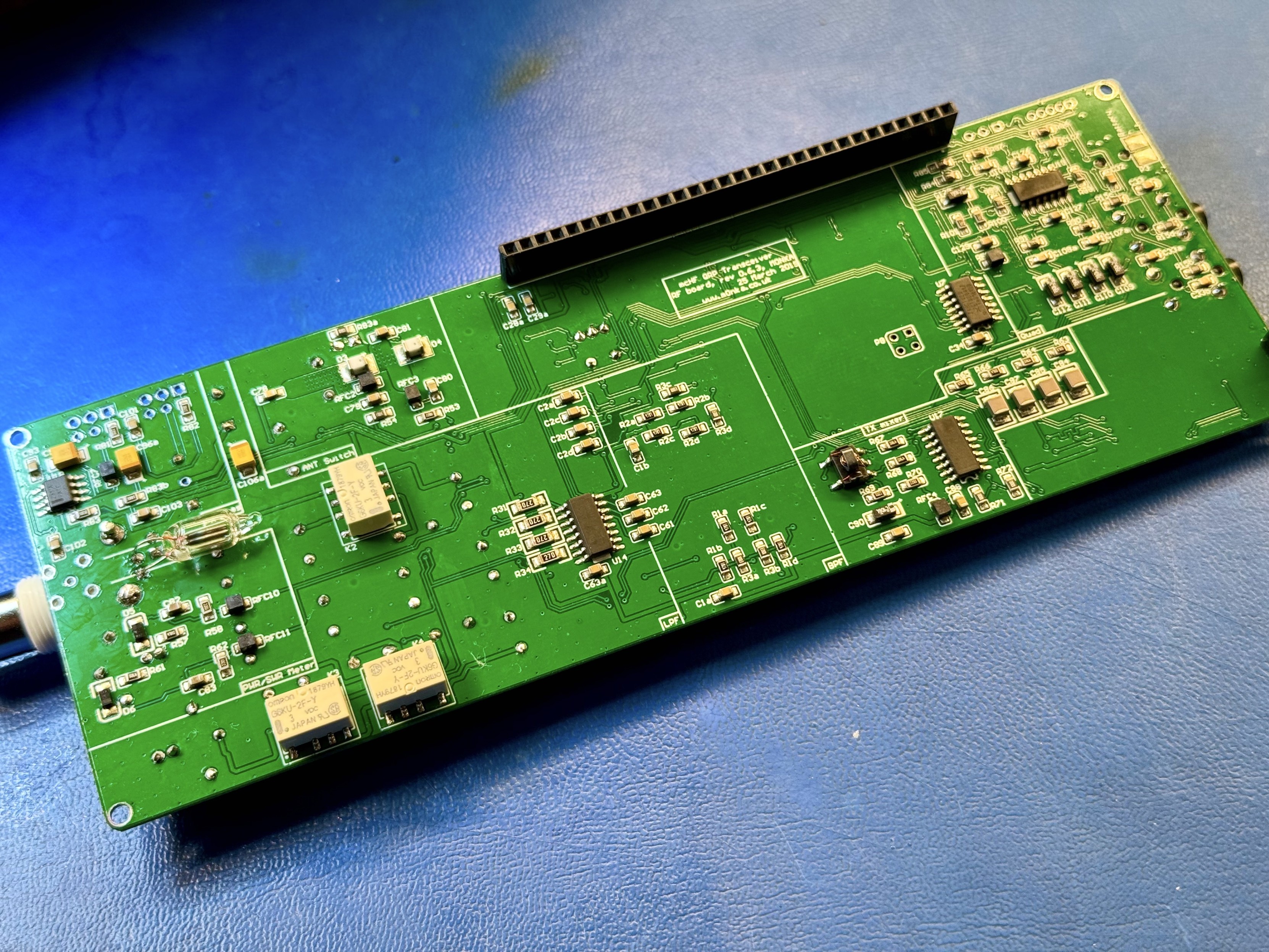
Now that we have the UI board assembled and tested it is turn to start on the RF board. Let's do the simple stuff first and solder on some connectors. Power jack, KEY and ACC, the BNC for the antenna, and an off the shelf balun. I have to order the temperature sensor chip that would be added in this step to for some extra TCXO temperature compensation stuff. #hamradio #kitradio #mchf

The mcHF board with the BNC, KEY, ACC, Power plugs soldered on. In the top middle of the board a small balun is also visible. The left lower corner is missing an SO-8 package that is meant for the temperature sensor.
Piotr Esden-Tempskiesden@chaos.social
2024-12-05

Now that the UI board is fully assembled we can test it! It is also time to update the bootloader and firmware! All we need is some jumper wires and a USB cable. And the verdict is… NO SMOKE! #hamradio #kitradio #mchf

First power up of the mcHF UI board. The firmware that the kit came with is quite old. V2.5.106 and the bootloader says “Unknown”. But NO SMOKE so that is great news so far!To power the board I used some jumper wires to connect the 5V supply to the board through pin 28 on the 30 pin connector. Then to force the board into the built in DFU bootloader I used a small grabber to short the P6 jumper. After the bootloader is updated we don’t need to use the jumper any more.After updating the bootloader I was able to flash the newest firmware onto the board. It is V2.12.2 from 2021, I have the feeling the firmware development slowed down a bit. ;) The new firmware immediately feels snappier and the encoders work more reliably.

Client Info

Server: https://mastodon.social
Version: 2025.04
Repository: https://github.com/cyevgeniy/lmst