
Aviation weather for Ponta Pelada airport in Manaus area (Brazil) is “SBMN 031600Z VRB04KT 9999 SCT025 BKN100 33/23 Q1010” : See what it means on https://www.bigorre.org/aero/meteo/sbmn/en #pontapeladaairport #airport #manaus #brazil #sbmn #pll #metar #aviation #aviationweather #avgeek vl
#pll

Les Inséparables Piou Piou célèbrent l’amour dans leur nouveau clip « PLL »
Le duo français Les Inséparables Piou Piou dévoile « PLL (Position Latérale de Love) », un single intime et lumineux inspiré du discours de mariage de Louis pour Solène. Avec une pop feel good à la croisée de Philippe Katerine et Richard Gotainer, ils invitent à célébrer l’amour simple et sincère à travers un clip innovant intégrant l’IA.
Une bulle créative et un duo authentique
Louis et Solène, les créateurs du bonheur
Les Inséparables Piou Piou, c’est avant tout l’histoire de Louis, anciennement connu sous le nom de Louis Piscine et lauréat des Inouïs du Printemps de Bourges, et de Solène, réalisatrice ayant collaboré avec Cléa Vincent. Dans leur maison, véritable foyer de création, le duo transforme le quotidien en univers musical et visuel. Pour eux, le bonheur n’est pas un hasard : c’est une énergie qu’ils cultivent et qu’ils transmettent à travers leurs chansons et images.
Une pop française feel good
Leur style, oscillant entre l’humour tendre et la sincérité, fait écho aux univers de Philippe Katerine et Richard Gotainer. Les deux artistes transforment des instants de vie banals en refrains lumineux et contagieux. Leur musique célèbre le quotidien tout en le sublimant, rappelant que le bonheur se construit et se chante avec authenticité.
« PLL » : de la déclaration intime à la chanson universelle
Une naissance dans l’intimité
Le premier single du duo, « PLL », est né d’un moment profondément personnel : le discours de mariage de Louis pour Solène. Captée sur le vif, la phrase « Mon amour, mon doudou, Solène, mon soleil, la première fois que je t’ai rencontrée j’ai été en PLL : Position Latérale de Love… » a été transformée en refrain universel, célébrant l’amour simple et sincère.
Une composition musicale rétro et tendre
Entre boîte à rythmes rétro, claviers des années 1980 et humour tendre, la chanson mélange sonorités nostalgiques et énergie contemporaine. « PLL » invite l’auditeur à partager un moment intime tout en restant léger et festif, reflétant l’esprit feel good et maison des Inséparables Piou Piou.
Un clip innovant et poétique
L’IA au service de l’amour
Pour le clip de « PLL », Louis et Solène ont choisi de plonger entièrement dans l’univers de l’intelligence artificielle. L’IA ne se contente pas d’illustrer la chanson : elle interprète leur quotidien, leurs courses à deux, leur enfance, leur première rencontre et tous les instants qui composent leur histoire d’amour. Le visuel devient ainsi une extension de leur vie et de leur poésie personnelle.
Une célébration de la vie et du temps
Le clip illustre l’idée que, lorsque l’on dit « oui » à l’être aimé, on accepte aussi l’enfant qu’il a été et le vieillard qu’il deviendra. À l’instar de la chanson, le clip transforme chaque instant en fête et en poésie visuelle, rappelant que l’amour véritable réside dans les détails du quotidien et dans les gestes simples partagés avec l’autre.
Un album à venir et une identité artistique forte
« Braqueur de bonheur », un projet attendu
« PLL » est le premier extrait du futur album du duo, intitulé « Braqueur de bonheur », attendu en 2026. Cette nouvelle étape promet de prolonger l’univers chaleureux et authentique des Inséparables Piou Piou, mêlant humour, tendresse et sensibilité artistique.
Un duo qui inspire
Avec leur approche sincère et créative, Louis et Solène incarnent un modèle de complicité et de joie de vivre. Leur musique et leur univers visuel rappellent que le bonheur peut se cultiver chaque jour et partagé avec les proches. L’alchimie entre les deux artistes rend chaque projet unique, entre intimité, humour et émotion.
https://www.youtube.com/watch?v=qmy375BDjFg
Les Inséparables Piou Piou offrent avec « PLL » une déclaration d’amour universelle, oscillant entre intimité et pop contagieuse. Le clip innovant, intégrant l’IA, sublime leur quotidien et illustre la poésie de l’amour simple. Avec ce premier single, le duo nous invite à célébrer la vie, le couple et la joie des petites choses.
#album2026 #clipMusical #declarationDamour #ia #lesInseparablesPiouPiou #louisPiscine #musiqueFeelGood #musiqueFrancaise #pll #popFrancaise #solene


FINAL FANTASY XIV Letter from the Producer LIVE Part LXXXIX https://www.yayafa.com/2606458/ #DAWNTRAIL #FF14 #FFXIV #FinalFantasyXIV(VideoGame) #Game #gaming #MMO #PLL #SQUAREENIX #スクウェア・エニックス #スクエニ #ファイナルファンタジー #黄金のレガシー


https://www.wacoca.com/games/1253258/ FINAL FANTASY XIV Letter from the Producer LIVE Part LXXXIX ##GAMING ##スクウェア・エニックス #Dawntrail #FF14 #FFXIV #FinalFantasyXIV(VideoGame) #Game #GameNews #games #GamingNews #GamingTrending #MMO #PLL #SQUAREENIX #TrendingGames #ゲーミング #ゲーム #ゲーム攻略 #ゲーム最新情報 #スクエニ #ドラゴンクエストV天空の花嫁 #ファイナルファンタジー #黄金のレガシー

FINAL FANTASY XIV Letter from the Producer LIVE Part LXXXIX https://www.playing-games.com/855242/ #Dawntrail #FF14 #FFXIV #FinalFantasyXIV(VideoGame) #games #gaming #GamingTrending #MMO #PLL #SQUAREENIX #TrendingGames #ゲーム #ゲーム攻略 #ゲーム最新情報 #スクウェア・エニックス #スクエニ #ファイナルファンタジー #黄金のレガシー


Fox sets Sunday NFL record; WNBA Playoffs start strong (even without Caitlin Clark)
Fox drew its best Sunday regular season NFL audience ever in Week 2, with a Super Bowl rematch…
#nflL #nflplayoffs #NFLPlayoffs #audience-analysis #data-and-insights #espn #Football #FoxSports #NFL #pll #WNBA
https://www.rawchili.com/nfl/379880/

Beautiful weather for takeoff from Ponta Pelada airport in Manaus area (Brazil) “SBMN 111400Z 13003KT CAVOK 30/23 Q1015” : See what it means on https://www.bigorre.org/aero/meteo/sbmn/en #manaus #brazil #pontapeladaairport #sbmn #pll #metar #aviation #aviationweather #avgeek #airport vl

Arduino and SP0256A-AL2 – Part 4
Having now tried both an Arduino and Raspberry Pi Pico as programmable clocks for the SP0256A-AL2, this post starts to look at some alternative solutions, starting with a HC4046 phase-locked loop, voltage-controlled oscillator clock.
- Part 1 – Basic introduction and getting started
- Part 2 – Arduino programmable clock
- Part 3 – Using a Raspberry Pi Pico as a programmable clock
- Part 4 – Using a HC4046 PLL as the clock
- Part 5 – Using an I2C SI5351 programmable clock
- Part 6 – Adding MIDI
https://makertube.net/w/8eRTaCvqb3bsmZEJFy94E3
Warning! I strongly recommend using old or second hand equipment for your experiments. I am not responsible for any damage to expensive instruments!
If you are new to microcontrollers, see the Getting Started pages.
Some Ideas
Whilst trawling around the Internet (and remembering a comment from my earlier posts), I found two existing projects where changing the frequency was used as a way to add pitch to the SP0256A-AL2:
- The previously mentioned MIDI Narrator: https://rarewaves.net/products/midi-narrator/
- A great blog post on SP0256A-AL2 pitch control: https://www.polaxis.be/2011/11/sp0256-al2-pitch-control/
Both use a VCO approach. The latter using a LTC6903 programmable oscillator; and the former using a CD4046 PLL device.
The LTC6903 looks like it would be a lot more complicated for me to use (especially being SMT), but I have some DIP 4046 devices already in the parts drawer so that is definitely an option for me.
I’ve also found (and now ordered) some breakout boards based on the SI5351 based programmable clock module. They all seem to follow Adafruit’s lead: https://learn.adafruit.com/adafruit-si5351-clock-generator-breakout/overview
One last thought – use a 555. No really! There are some versions that can go up o 3, 4 or even 5MHz apparently, see: https://en.wikipedia.org/wiki/555_timer_IC#Derivatives Of course having that in any way programmable might be a challenge, but it isn’t out of the question.
4046 VCO/PLL
A voltage-controlled oscillator is just what it sounds like. An oscillator whose frequency is related to the level of a control voltage on its input.
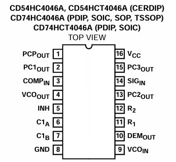
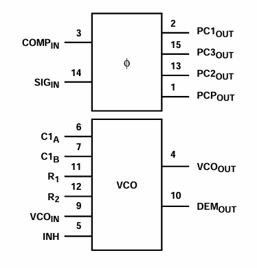
Here is a pinout and functional view of the 4046 from the TI 74HC4046/74HCT4046 datasheet. This provides several phase comparators and a voltage-controlled oscillator to create a phased-locked loop controller.
A key statement is the following:
“The VCO requires one external capacitor C1 (between C1A and C1B) and one external resistor R1 (between R1 and GND) or two external resistors R1 and R2 (between R1 and GND, and R2 and GND). Resistor R1 and capacitor C1 determine the frequency range of the VCO. Resistor R2 enables the VCO to have a frequency offset if required.”
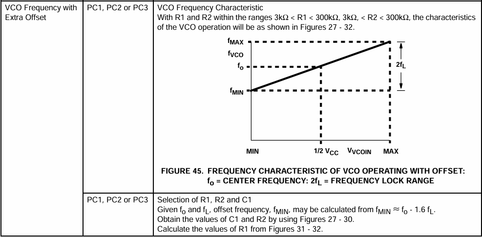
The “application information” section describes the “with offset” operation:
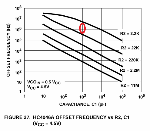
There are a lot of graphs of characteristics in the datasheet for the various combinations of R1, R2 and C1 – these are the “figure 27-32” mentioned above. Actually, to cover all options, there are figures 10 through to 43, but most of those cover other situations.
The criteria for selecting R1, R2 and C are:
- R1 Between 3kΩ and 300kΩ
- R2 Between 3kΩ and 300kΩ
- R1 + R2 Parallel Value > 2.7kΩ
- C1 Greater Than 40pF
For the MIDI Narrator, the values being used are as follows:
- R1 = 1.5K to 2.5K (adjustable)
- R2 = 12K
- C1 = 1nF
Which I believe puts it in the following areas of the performance curves, although they aren’t strictly within the state required ranges…:
So without detailed calculations and measurements, I think this puts the (centre) offset frequency at a low-number of MHz (extrapolating for 12K at 5V) and the Max/Min ratio (R2/R1) at something around 4 to 8.
I believe, from looking at the other charts, that a higher R1 or C value gives a lower frequency. There are graphs for the following with the stated approx frequency ranges at 4.5V:
- 1M5, 100nF: 0 < Freq <100Hz
- 150K, 100nF: 0 < Freq < 1kHz
- 5K6, 100nF: 0 < Freq < 20kHz
- 150K, 50pF: 0 < Freq < 1.5MHz
One last thing to note from figure 32 – it states that a Vin of 0.95 VCC will generate the maximum frequency and 0V for the minimum.
It turns out I have some CD4046 in my parts box, not a HC or HCT 4046. On initial inspection, there doesn’t seem to be a lot of difference that would significantly affects my messing around. Some of the pins (that I’m not using) have different functions:
But as I’m not using those pins, that probably won’t matter. But then on closer inspection, I can see a key difference that definitely will affect my messing about – the operating frequency ranges:
- HC/HCT4096: Up to 18MHz at VCC=5V.
- 4096: Up to 1.4MHz at VDD=10V.
And digging into the detailed spec for the CD4046, when running at 5V the maximum is down to just 0.8MHz typical.
So I could use them to test out some general principles but need a HC/HCT version to really achieve what I’d like to do.
At this point my understanding was starting to struggle, and those graphs weren’t helping much. So I just went ahead and built the version of the circuit from the Rarewaves MIDI Narrator. I really wasn’t having much luck with it as is however, so started fiddling about with different components and an oscilloscope to see if I could make any sense from it.
There is a good article about the basics of a 4046 based VCO-driven PLL oscillator output here: https://hackaday.com/2015/08/07/logic-noise-4046-voltage-controlled-oscillator-part-one/
I was finding that the output wasn’t a particularly clean square wave, and at higher frequencies was pretty much triangular. At this stage I don’t know how much of that is my measuring equipment. I have a scope probe with a 10pF capacitance apparently, so a 10K resistor and 10pF capacitor do create a low-pass filter that significantly rounds off the signal.
But more significantly, the peak to peak voltage was greatly reduced to around 1.5Vpp with a significant BC bias. That wasn’t much use as a clock signal for me – from Part 3 I know the SP0256A-AL2 requires <0.6V for a LOW and >2.5V for a HIGH. Basically scope or on scope the output was pretty unreliable for me.
I’d included the 10K resistor between the 4046 and SPA256A-AL2 as per the circuit for the MIDI narrator. But without that resistor, the clock is much cleaner and has much more useful levels, so I removed it. Later experiments show that a 1K resistor seems to work fine too.
I also found that the suggested 1nF capacitor wasn’t giving me a particularly useful range. In the end, 4.7nF seemed to work well for me. Eventually after testing a range of different resistor values, I went back to 12K and 1.5K + 1K pot from the original circuit. This gives me:
- The frequency range set by a combination of 4.7nF and 12K.
- A frequency offset of between 1K and 2.5K is configurable.
I believe this will pull the frequency offset down slightly from the previous values to something between 100kHz and 600kHz, according to the charts, but it gives me a very useful range between around 1MHz and 5MHz once tuned slightly with the trimpot.
When going through the LM358 the usable voltage range for the VCO seems to be between ~2V and 3V for the 1MHz to 5MHz range. 0V is currently giving me 120kHz, tweaking of the offset resistor (R2 = 12K) helps here – 3K3 makes that around 500kHz, making the useful input voltage now around 1.5V to 3V. The issue is that reducing R2 starts to get to the point where the condition that R1||R2 > 2K7 no longer holds true. But either seems fine for some experimenting for now.
My final circuit used for now is as follows:
The CLK output was plugged directly into the SP0256A-AL2 OSC 1 input, with OSC 2 connected to GND.
The control voltage pot goes through a LM358 which might not be strictly necessary in this case, but helps to at least stabilise the input voltage to the VCO. It might also be useful when I switch to programmatically driving the control voltage from a microcontroller.
The usable clock frequency range is adjusted using the trimpot. Eventually, as mentioned, I settled on a range of around 1MHz to 5MHz. It will go lower, but that isn’t so useful for driving the SP0256A-AL2.
Arduino PWM Voltage Control
To get the Arduino to set the control voltage, requires generating a PWM signal which can be pretty simply done with analogWrite().
The default PWM frequency is around 400kHz without messing about directly with Arduino timers. This will need filtering though, but a simple low-pass filter should easily work here, especially as the frequency won’t be changing very often.
I just went back to the MIDI narrator circuit and could see that a 100K/220nF filter was used. Putting these into a low-pass filter calculator gives a cut-off frequency of just under 8Hz. This generates a pretty smooth output.
There is a balance between the frequency range and offset chosen for the 4046 by the selection of R1, R2 and C, and the voltage range sent out of the Arduino. After a fair bit of messing around, I settled on the following:
- R1 = 3K3
- R2 = 10K
- C = 560pF
Then used analogWrite() with values between 60 and 200 to generate voltages and frequencies as follows:
- analogWrite() value range: 60 to 200
- PWM smoothed voltage range: 1.3V to 3.6V
- LM258 output voltage range: 1.3V to 3.3V
- Clock frequency range: 2.2MHz to 5MHz
Setting up the clock via PWM voltage control is done as follows:
#define SP0_CLOCK 10 // D10
void clockSetup () {
  pinMode(SP0_CLOCK, OUTPUT);
  analogWrite(SP0_CLOCK, 128);  // Approx 2.5V output
}

void setClock (int clock) {
  analogWrite(SP0_CLOCK, clock);
}
Closing Thoughts
This seems to work really well. The control using a pot isn’t particularly reliable, but that is quite different if generating a control voltage from a microcontroller.
I still need to do some calibrations to work out what voltages create which frequencies and then what pitch of voice reproduction that seems to produce, but that can come later. For now it is enough to know it appears to work albeit in still quite a hand-wavy kind of way.
As an aside, whilst trawling around the Internet for this one I stumbled across the CTS256A-AL2 device. This is a microcontroller (I think it is 8051 based, based on a PIC7041) that performs text to allophone conversion for pairing with a SP0256A-AL2 for a complete text to speech system.
There are some details, and an interesting DIY board, here: https://www.smbaker.com/cts256a-al2-text-to-speech-board and an older project here: https://8051bits.com/misc-projects/speech%20-%20music%20synthesizers/speech-mus-syn.html
Unfortunately these seem very hard to come by these days, but there is some interesting emulation code here: https://github.com/GmEsoft/SP0256_CTS256A-AL2
And a pretty thorough discussion about the device and its running code here: https://www.retrobrewcomputers.org/forum/index.php?t=msg&th=816&goto=10847
Kevin

Today's Hitting-the-Way-Back-Machine Show:
@GregMcElroy@twitter.com | @trevorbaptiste9@twitter.com | @andyholloway@twitter.com | @RodWoodson26@twitter.com
📺 https://therokuchannel.roku.com/watch/e25551b0…
📻https://audacy.com/stations/riche…
☎️ 844-204-RICH

#PLL
Boston - 140
@SportsGrid@twitter.com

FINAL FANTASY XIV Letter from the Producer LIVE Part LXXXVIII https://www.playing-games.com/733421/ #Dawntrail #FF14 #FFXIV #FinalFantasyXIV(VideoGame) #games #gaming #GamingTrending #MMO #PLL #SQUAREENIX #TrendingGames #ゲーム #ゲーム攻略 #ゲーム最新情報 #スクウェア・エニックス #スクエニ #ファイナルファンタジー #黄金のレガシー
https://www.wacoca.com/games/1188162/ FINAL FANTASY XIV Letter from the Producer LIVE Part LXXXVIII ##GAMING ##スクウェア・エニックス #Dawntrail #FF14 #FFXIV #FinalFantasyXIV(VideoGame) #Game #GameNews #games #GamingNews #GamingTrending #MMO #PLL #SQUAREENIX #TrendingGames #ゲーミング #ゲーム #ゲーム攻略 #ゲーム最新情報 #スクエニ #ドラゴンクエストV天空の花嫁 #ファイナルファンタジー #黄金のレガシー

How to Watch the 2025 PLL All-Star Game Live on Roku, Fire TV, Apple TV & More on July 5

‘Pretty Little Liars’: Where the Cast and Characters Are Now
#TV #TVNews #AshleyBenson #Evergreen #Evergreenpost #Freeform #IanHarding #KeeganAllen #LucyHale #MarleneKing #PLL #PrettyLittleLiars #SashaPieterse #ShayMitchell #TroianBellisario #TylerBlackburn
https://www.hollywoodreporter.com/lists/pretty-little-liars-cast-characters-now/
https://www.wacoca.com/games/1167914/ FINAL FANTASY XIV Letter from the Producer LIVE Part LXXXVII ##GAMING ##スクウェア・エニックス #Dawntrail #FF14 #FFXIV #FinalFantasyXIV(VideoGame) #Game #GameNews #games #GamingNews #GamingTrending #MMO #PLL #SQUAREENIX #TrendingGames #ゲーミング #ゲーム #ゲーム攻略 #ゲーム最新情報 #スクエニ #ドラゴンクエストV天空の花嫁 #ファイナルファンタジー #黄金のレガシー
FINAL FANTASY XIV Letter from the Producer LIVE Part LXXXVII https://www.playing-games.com/689376/ #Dawntrail #FF14 #FFXIV #FinalFantasyXIV(VideoGame) #games #gaming #GamingTrending #MMO #PLL #SQUAREENIX #TrendingGames #ゲーム #ゲーム攻略 #ゲーム最新情報 #スクウェア・エニックス #スクエニ #ファイナルファンタジー #黄金のレガシー
‘Pretty Little Liars’ at 15: Cast and Creator Spill Secrets — From “A” to Most Talked-About Couples — and Share Hopes for a Reunion Movie
#TV #TVFeatures #Anniversary #AshleyBenson #Freeform #IanHarding #LucyHale #MarleneKing #PLL #PrettyLittleLiars #SashaPieterse #ShayMitchell #TroianBellisario #TylerBlackburn


In 2025, for the first time, the Alfie Jacques Ambassador award will be presented to two recipients — Oren Lyons Jr. and Roy Simmons Jr. — alfieaward.com
#PLL #NLL #lacrosse #HHH #LikeNoOther
Client Info
Server: https://mastodon.social
Version: 2025.07
Repository: https://github.com/cyevgeniy/lmst