#programChange

Simple DIY Electronic Music Projectsdiyelectromusic.com@diyelectromusic.com
2025-06-29

XIAO ESP32-C3 MIDI Synthesizer – Part 6

Expanding on my previous posts, I thought it might be interesting to see how I might be able to add some additional IO to the MIDI Synth. This is an exploration of some options there.

  • Part 1 – Getting started and getting code running.
  • Part 2 – Swapping the ESP32-C3 for a SAMD21 to get USB MIDI.
  • Part 3 – Taking a deeper look at the SAM2695 itself.
  • Part 4 – A USB MIDI Synth Module using the SAMD21 again as a USB MIDI Host.
  • Part 5 – A Serial MIDI Synth Module using the original ESP32-C3.
  • Part 6 – Pairs the Synth with a XIAO Expansion board to add display and potentiometers.

Warning! I strongly recommend using old or second hand equipment for your experiments.  I am not responsible for any damage to expensive instruments!

These are the key tutorials for the main concepts used in this project:

If you are new to microcontrollers, see the Getting Started pages.

The Synth Grove Connector

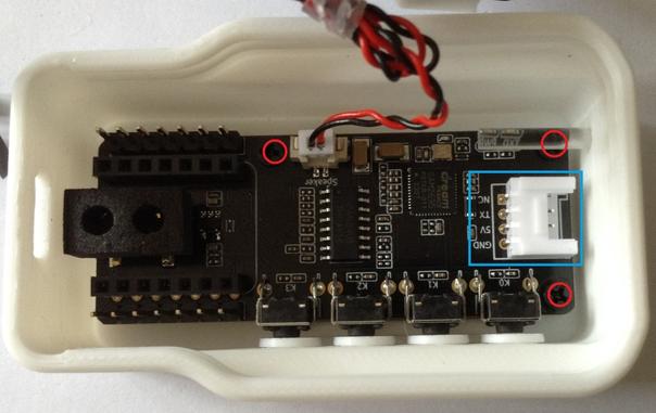
One option to immediately explore for me was the Grove connector on the Synth – highlighted by the blue rectangle in the photo below. I’m thinking at this stage of the XIAO Expander Module (more here) and how that might give some options for easily hooking up to the Synth.

There one obvious issue with this, and one not so obvious issue.

First, of course, there is no access to this connector through the case. My initial thought was to simply remove the PCB from the case and use it as a stand-alone board. On initial inspection it seemed that there were two screws holding it down. Not so, a more thorough inspection (after remove the two screws and still not being able to remove it), revealed a third screw underneath the “light pipe” for the LEDs.

Unfortunately that light pipe is pretty well wedged into the case making removal particularly tricky. But without removing the light pipe, it isn’t possible to get to the screw at all.

I did wonder about making a hole in the 3D printed case. A better option might be to get hold of the published 3D print files and add a hole and make my own (they are available via the product page).

But both options would probably end up changing the original case somehow – even if printing my own, I still need to get the original PCB out somehow and that brings me back to the light pipe issue.

The second issue isn’t quite so obvious. In that photo we can see that the pins for the Grove connector are labelled as follows (top to bottom):

  • NC
  • TX
  • 5V
  • GND

The UART on the XIAO expander board, which I’d like to use, is labelled:

  • RX7
  • TX6
  • 3V3
  • GND

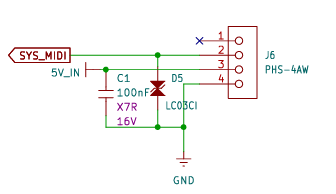
Checking in with the Synth schematic, the connector is wired as follows:

SYS_MIDI connects to the MIDI_IN pin of the SAM2695, so actually connecting “TX to TX” in this instance should be ok.

5V might be an issue though, as it really does look like (to me) that it really means 5V – it is the input to the TPL740F33 that generates the 3V3 power signal, as well as feeding the amplifier directly. The datasheet of the TPL740F33 does seem to imply that if receiving 3V3 it can still generate 3V3 so it might be ok? The amplifier obviously won’t be as powerful though running off 3V3.

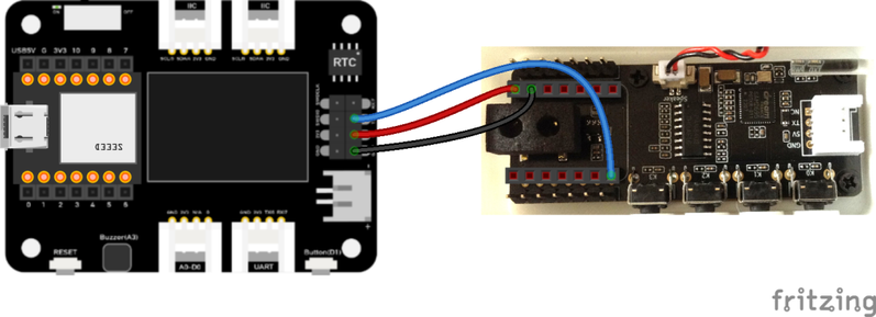
Anyway, for now, instead I’ve just opted to use the GPIO again, wired into the expansion sockets with the XIAO removed.

At the XIAO expander end, I’ve used the additional pins rather than the Grove connector, as they support a 5V output.

The downsides to this approach:

  • I’m not using the Grove connectors, which would have been really neat.
  • I have no access to the four buttons on the XIAO MIDI Synth.

But I do now have access to two I2C Grove connectors, a GPIO Grove, and the RX part of the UART Grove too as well as the on-board display.

If a XIAO SAMD21 is used, then the previous code for USB to the Synth can be used directly – see XIAO ESP32-C3 MIDI Synthesizer – Part 2.

If the XIAO ESP32-C3 is used, then an additional serial MIDI connection is required. This can be connected to the Grove UART connector (using the RX pin, and leaving TX unconnected) or the RX pin of the additional 8-way pin header on the expansion board. Then the code from this will work directly: XIAO ESP32-C3 MIDI Synthesizer – Part 5.

Adding a Display and Program Control

I already have some code that has done this for a XIAO on an expansion board here XIAO SAMD21, Arduino and MIDI – Part 6.

But for this to work usefully with the Synth module, I need to adjust the routing so that MIDI goes from USB to serial, but the program change messages are also sent via serial to the synth module. That has already been address in previous parts, to I just need to merge the code with that from XIAO ESP32-C3 MIDI Synthesizer – Part 4.

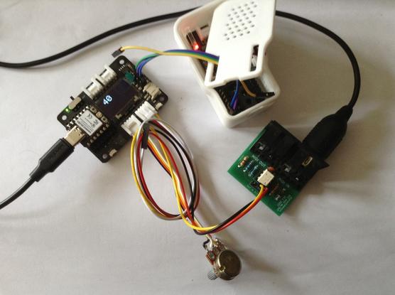
This is the result.

There is a bit of jitter on the analog pot, but that is only because I’m using the original fairly simplified algorithm to detect changes. If I was fussed about it, I’d reuse the averaging class from Arduino MIDI Atari Paddles. And to be honest, a capacitor on the pot would probably go quite a long way too…

As a test, I also powered the device from the Grove UART port connecting it as follows:

  • Expander GND – GND Synth
  • Expander 3V3 – 5V IN Synth
  • Expander TX – RX/D6 Synth
  • Expander RX – N/C

And this all worked fine. So I think a Grove to Grove lead would work fine if I had access to the Synth’s Grove port.

This does mean that the exact same code can work with the M5 Synth module using a Grove to Grove lead. The downside of this, even though it is a lot simpler in connectivity terms, is that there is now external audio out like there is on the XIAO Synth.

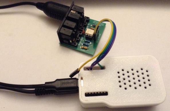
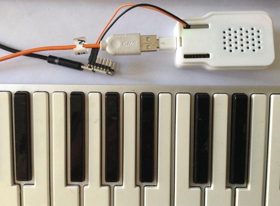
For completeness the same code can be used with the XIAO ESP32-C3 and serial MIDI, see the photo at the start of this blog.

To turn off all USB handling in the code, the following must be commented out:

//#define HAS_USB
//#define SER_TO_USB
//#define MIDI_USB_PCCC

For other parts of the code, the Arduino abstraction for A0 maps over to the ESP32-C3 fine. The only thing to watch out for is the increased analog resolution from 10 to 12 bits, but a call to analogReadResolution(10) drops that back to the expected 10 bits.

Oh and the Serial port to use is different:

  • XIAO SAMD21: Serial1
  • XIAO ESP32-C3: Serial0

Find it on GitHub here.

Closing Thoughts

If I can be bothered, it would be nice to actually display the General MIDI voice name on the display. The SAM2695 also has its MT-32 mode, so having some means of selecting that might be interesting too.

And so far I’ve largely only messed about with driving it on a single MIDI channel, so there is a lot more that could be done there.

Kevin

#controlChange #esp32c3 #midi #programChange #SAM2695 #samd21 #usbMidi #xiao
Simple DIY Electronic Music Projectsdiyelectromusic.com@diyelectromusic.com
2025-06-28

XIAO ESP32-C3 MIDI Synthesizer – Part 5

So I was somewhat guilty that I’d replaced the XIAO microcontroller in the last couple of parts to get USB MIDI, so in this one I put the original ESP32-C3 back in and now have a version of Part 4 for serial MIDI.

  • Part 1 – Getting started and getting code running.
  • Part 2 – Swapping the ESP32-C3 for a SAMD21 to get USB MIDI.
  • Part 3 – Taking a deeper look at the SAM2695 itself.
  • Part 4 – A USB MIDI Synth Module using the SAMD21 again as a USB MIDI Host.
  • Part 5 – A Serial MIDI Synth Module using the original ESP32-C3.
  • Part 6 – Pairs the Synth with a XIAO Expansion board to add display and potentiometers.

https://makertube.net/w/wez7y8WrxrNgkF1F1QX2AX

Warning! I strongly recommend using old or second hand equipment for your experiments.  I am not responsible for any damage to expensive instruments!

These are the key tutorials for the main concepts used in this project:

If you are new to microcontrollers, see the Getting Started pages.

The Circuit

This goes back to adding a 3V3 compatible serial MIDI board using the XIAO GPIO breakout pins as described in Part 1.

This is powered from 3V3 and GND and connected to D6/RX (which may or may not be GPIO 6).

The Code

This is all the same code from Part 4 but with the USB handling removed and the bespoke serial port writing replaced with calls into the Arduino MIDI Library using Serial0 as the MIDI device:

MIDI_CREATE_INSTANCE(HardwareSerial, Serial0, MIDI);

void midiSendProgram (uint8_t prog) {
MIDI.sendProgramChange(prog, MIDI_CHANNEL);
}

void midiSendControl (uint8_t cmd, uint8_t d) {
MIDI.sendControlChange(cmd, d, MIDI_CHANNEL);
}

void setup() {
MIDI.begin(MIDI_CHANNEL);
...
}

void loop() {
MIDI.read();
...
}

Once again I’m relying on the fact that the serial MIDI transport has an automatic MIDI THRU enabled between RX and TX.

Find it on GitHub here.

Closing Thoughts

Whilst the USB MIDI host solution is a lot more convenient in terms of being able to plug in MIDI controllers, the serial MIDI version is a lot easier when it comes to programming and powering the device.

The video shows a PC streaming a MIDI file to the XIAO Synth whilst I’m changing volume and voice.

Kevin

#controlChange #midi #programChange #SAM2695 #xiao

Simple DIY Electronic Music Projectsdiyelectromusic.com@diyelectromusic.com
2025-06-27

XIAO ESP32-C3 MIDI Synthesizer – Part 4

In Part 2 I looked at how to add USB MIDI to the XIAO MIDI Synthesizer and in Part 3 I looked at some of the properties of the SAM2695 synth chip itself. This post combines the two into a relatively simple, but playable, synth.

  • Part 1 – Getting started and getting code running.
  • Part 2 – Swapping the ESP32-C3 for a SAMD21 to get USB MIDI.
  • Part 3 – Taking a deeper look at the SAM2695 itself.
  • Part 4 – A USB MIDI Synth Module using the SAMD21 again as a USB MIDI Host.
  • Part 5 – A Serial MIDI Synth Module using the original ESP32-C3.
  • Part 6 – Pairs the Synth with a XIAO Expansion board to add display and potentiometers.

https://makertube.net/w/kaZT6zPjKUmGQp17J15fMM

Warning! I strongly recommend using old or second hand equipment for your experiments.  I am not responsible for any damage to expensive instruments!

These are the key tutorials for the main concepts used in this project:

If you are new to microcontrollers, see the Getting Started pages.

The Circuit

I’m wanting to plug a USB MIDI keyboard into my XIAO Synth, so I’m going to swap the XIAO ESP32-C3 out once again for a XIAO SAMD21 as described in Part 2. A future post will go back and create a serial MIDI version using the unmodified XIAO Synth.

Recall that a source of 5V power is required, and below I’m just using the 5V USB passthrough from the original XIAO ESP32-C3.

There is one issue to watch out for in this kind of configuration. Depending on how the USB power is provided, there might not be a common ground point between the XIAO’s power and any audio amplification used.

Apparently GND is always passed through many USB charger blocks.

To prevent interference and noise, it may be necessary to ground the USB connection providing power.

The Code

I’m using a combination of the SAMD21 USB Host Library “USB MIDI Converter” example and some GPIO and MIDI handling.

The general thread of the code will be as follows:

loop():
Do any USB host processing (e.g. plug-and-play)
IF USB MIDI messages received THEN
Send to serial MIDI
IF any buttons pressed THEN
Handle button IO
Generate any additional MIDI messages as required
Send to serial MIDI

In particular it should be noted that the MIDI “listening” is one-way only USB to serial MIDI; and that any internal control events that generate MIDI are also only going one way – to serial MIDI.

The buttons will be used to do the following:

  • Button 0 and 1: Program Select Up/Down
  • Button 2 and 3: Channel Volume Up/Down

A much more sophisticated interface could be developed – e.g. using one of the buttons to change modes for the other buttons, to allow the selection of different things, but for now, this is plenty.

There are several layers to the code to allow this however, so I’ll cover them briefly here.

  • Main Loop button IO: Checks for the main H->L, L->H, L->L, H->H events and calls functions for all but the last (buttons are pulled high so H->H means “nothing happening).
  • Event functions for Pressed, Released, Hold which call program or volume handling functions as required.
  • Program/volume handling functions that update the values and then trigger the appropriate MIDI messages to be sent.
  • Functions to send a MIDI Program Change or Control Change message as required.

In the end I’ve only triggered events on button Pressed, so the Release and Hold functions don’t cause any further action to take place, but the model is there for use in the future if required.

Note: as I’m not using the Arduino MIDI Library, I just build PC or CC messages directly and call out to Serial1.Write as shown below.

void midiSendControl (uint8_t cmd, uint8_t d) {
uint8_t buf[3];
buf[0] = MIDI_CC | (MIDI_CHANNEL-1);
buf[1] = cmd;
buf[2] = d;
Serial1.write(buf, 3);
}

Simple, but it works. Note PC are only two bytes in size not three.

If performance seems to be an issue, then I have a few things to adjust in the scheduling:

  • I can split the digitalRead() of each button over several scans to allow MIDI processing to happen in between.
  • I can switch to the XIAO equivalent of direct PORT IO to try to read all IO pins at the same time. I don’t know what this looks like for the SAMD21 however and it would make it hardware specific, so I’d really rather not do that.
  • I can remove the waiting of 1mS. This was in the original USB converter, so I kept it in here too. I ought to measure the free running loop() time to see if it is needed.

Find it on GitHub here.

Closing Thoughts

In the video I cycle through a few of the programs whilst controlling the synth from a keyboard.

At one point I remove the external audio connection (yes, I should have turned it down first!) to contrast the sound with the internal speaker. Yes, it is a bit “tinny” but it isn’t too bad.

This really is just the very “tip of the iceberg” given the whole range of parameters available that were mentioned in Part 3.

Kevin

#controlChange #midi #programChange #SAM2695 #samd21 #usbHost #xiao

Simple DIY Electronic Music Projectsdiyelectromusic.com@diyelectromusic.com
2024-09-10

I’ve wanted to create a non-microcontroller, discrete logic MIDI circuit for some time. I thought it would be interesting to have a few chips that could generate a specific sequence of bytes corresponding to a MIDI message. Note: I’m still talking individual chips here, not just gates and definitely not individual transistors, so perhaps “discrete logic” is a bit of a stretch…

I’ve toyed with various ideas, but not actually properly experimented with anything, but the use of 4017 counters was always there as a possibility.

People have wound up the clocks on a CV step sequencer like these to audio frequencies and created a simple wavetable oscillator.

So seeing as I have a number of “Baby8” CV Step Sequencer PCBs that I’ve just reworked, that will only really work in cascade mode – and seeing as each has 8 switches that control the level of the output GATE signal I thought I would wind the clock up even further and see if I could get it to generate MIDI.

Just don’t ask why.

https://makertube.net/w/oQtoQ4Dgx3rcfBugzr6cyu

Warning! I strongly recommend using old or second hand equipment for your experiments.  I am not responsible for any damage to expensive instruments!

If you are new to electronics, see the Getting Started pages.

Parts list

  • 3x 4017 decade counters.
  • 1x 4093 quad NAND gate (or a dual INVERTER of some sort).
  • 3x failed “Baby8” CV Step Sequencer PCBs (!) with the following:
    • 27x pcb mount SPDT slider switches (2.54mm pitch).
    • 24x 1N4018 small signal diodes.
    • 12x 100K resistors.
    • 3x 100nF capacitors.
    • 3x 100pF capacitors.
    • 3x 8-way right angle pin headers.
    • 3x 8-way right angle pin header sockets.
  • 31250Hz clock signal, e.g.:
    • 1x NAND gate from the 4093.
    • 1x 300R resistor (1% accuracy).
    • 1x 33nF capacitor.
  • 2x 220R resistors.
  • 1x 10K resistor.
  • 1x 5 pin MIDI DIN socket.
  • Solderless breadboard and jumper wires.

The Circuit

I’m not going to go through the core circuit, as the whole point is to reuse the V1 PCBs from my “Baby8” CV Step Sequencer. I only need to use them as a GATE sequencer – no pitch (CV) or trigger is required, so I can ignore the pots, LEDs, the NAND circuitry, and in most cases the clock too.

I also don’t actually need the rotary switch to select the number of steps – I’m going to be fixing it at 8. I could solder in a clock on one of the boards, but the component values would need changing to give me a steady 31250 Hz clock. I’ve opted to use the same circuit but externally on breadboard to achieve this.

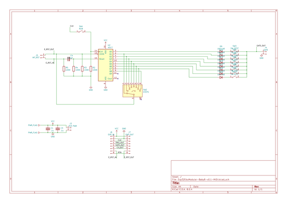
Here is the part of the Baby8 schematic I’m actually using.

To generate the clock, I put some values in an online Schmitt trigger oscillator calculator and with some trial and error came up with the use of a 330R resistor and 68nF capacitor for my 31,250 Hz oscillator. But in practice it turns out that 300R and 33nF is much better for what I need. I don’t know where the discrepancy lies – my circuit or the calculator, but with these values I have a good enough (for a couple of bytes) MIDI clock.

The MIDI OUT circuit could possibly have been driven directly off the GATE signal but seeing as I have some inverters kicking around (well, actually several NAND gates from my 4093) I thought I’d buffer the signal and then send it to a standard MIDI OUT circuit.

I’ve only used one inverter, so the MIDI signal will be the inverse of the GATE driving it.

During use, I found I had to pull the GATE signal to GND via a 10K resistor to keep it effective, so again that backs up the idea of using a buffer for the MIDI side to me to keep the two parts independent.

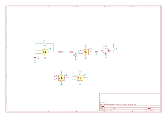
Here is the rest of the schematic with the extras I require:

The whole thing is powered directly from a 5A power supply (in my case actually a DIY circuit using a L7805 – a spare from my MIDI Matrix Patch Bay).

Basic Functionality

The general idea is to have three of these boards cascaded. MIDI consists of several 8-bit values per message, but each of the 8-bits is also accompanied by a START and STOP bit. This means a typical three-byte message (i.e. most of them) consists of 30 bits and a two-byte message (e.g. Program Change) is 20 bits.

I’ve opted to implement something that can generate two-byte, Program Change messages using the 8 switches on three Baby 8s and hooking that up to the GATE signal. The switches will determine if the signal is HIGH or LOW for that stage in the sequence which will be clocked at the MIDI baud rate of 31,250 Hz.

The Baby 8’s will need to start, cascade through an entire sequence of 24 steps (to cover the required 20 bits), and then stop. To do this I’m going to use the “RST return” feature of my PCBs and the RUN switch on the first Baby 8.

Once everything is wired up to the external clock and MIDI OUT circuit, the basic sequence will be as follows. Note I have to power OFF if this is the first use to ensure everything starts in the right place. Further uses do not require a power cycle.

  • Set RUN to STOP on the first Baby 8. It will always be left on RUN on the other two.
  • Power ON if this is the first use.
  • Set the byte values to be sent via the switches.
  • Press the RESET button which temporarily completes the RST chain and ensures the sequencer cycles round to the first step, outputs that GATE value which it will hold and then halts.
  • Set RUN to RUN which then runs through all 24 steps setting the GATE level according to the switch settings.
  • Repeat sequence from the beginning to send further messages.

Assembly and Build

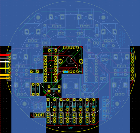
I don’t need to build complete Baby 8 boards – as already indicated I only really want the counter and GATE outputs. These are the sections of the V1 PCB I need to be populated:

As I’m not using the rotary switch, and all the components I’m adding still leave me the option of populating the rest of the components at some point in the future to restore the full (albeit with issues) “Baby 8” functionality, I’ve used the “fishing line trick” to add a non-soldered link between the switch’s step #8 and the return (as indicated in cyan above).

Note that a jumper is required on the last Baby 8 to route the RST signal back through the boards to connect to a manual RESET switch.

Generating MIDI from Discrete Logic

In order to produce a MIDI Program Change message, the following sequence of bytes is required.

MIDI Msg = CMD + DATA
0xCn 0xdd
!! ++--- 7 bit data byte for program number (1..128 = 0x00..0x7F)
!+-------- MIDI channel (1..16 = 0x0..0xF)
+--------- MIDI Program Change command (0xC)

So for MIDI channel 1, the sequence, including START (S) and STOP (E) bits, will be as follows. Note MIDI has the least significant bit sent first, just after the START bit, so reading from left to right is the sequence in which the bits are sent too – time flows to the right (just like an oscilloscope trace).

0xC0 0x04  -> Program Change to voice 5

0 0000 0011 1 0 0010 0000 1
S Ch1 PC E S Data=4 E

This requires the switches set as follows:

HLLL LLLL HHHL LLLH LLLH HHHH
+------- STOP and remain HIGH to finish
++++-+++-------- 7 bits of data to encode 0x04
+----------------- START
+------------------ STOP
++ ++------------------- 4 bit command 0011 = 0xC (PC)
++ ++------------------------ 4 bit channel 0000 = 0x0 (Ch 1)
+----------------------------- START
+------------------------------ Preamble starts HIGH

Due to the use of the inverter as a MIDI OUT buffer, a H is generated from the GATE being LOW – i.e. having a step skipped (switch down).

In order to ensure I get a good START bit, the first switch (which is the “hold” step until the RUN is started) is set to generate and therefore hold a H level.

The program number to be set is chosen by encoding a number between 0 and 127 (corresponding to programs 1 to 128) backwards (the step sequence is also left to right) on the appropriate 7 switches – four on the second Baby 8 and three on the last.

Here are some traces of the boards in action. Both traces show selecting voice 5 (sending byte 0x04 as data).

The first is a trace from my Arduino MIDI Logic Analyser, which also gives an estimate of the baud rate in use. I had to modify it slightly to cope with two-byte messages – it was only dealing with three-byte messages before. I’ll update the code and message handling one day.

We can see that the baud rate is still a little high compared to what is required, but it seems close enough for just a two-byte message.

And here is an oscilloscope trace of the clock signal (blue) and the MIDI OUT signal (yellow) for the same message.

The first drop is the START bit. The two highs are the end of the PC byte and the STOP bit. Then there is another START bit and then binary 0010 – which is 4 when encoded LSbit first (on the left) followed by more zeros until the final high STOP bit and a few trailing highs.

Conclusion

I’ve wanted to do something like this for a while now so actually really quite enjoyed this somewhat pointless activity. Of course, using PCBs like these is massive overkill and the utility of the result is very questionable.

The video shows me selecting different patches on a MiniDexed. You can just about see the voice name change on the display, but hopefully you hear the difference going from Brass 1 to Strings 1, Strings 3, Strings 2 and back to Brass 1 again.

But the V1 PCBs were sitting on my bench, and for the sake of soldering on a few cheap components provided an easy way to test the idea.

And I’ve not soldered anything on that means I couldn’t turn these back into full (but limited) Baby 8 sequencers if I wanted.

So I’d say this is a win. But as I say, just don’t ask me why.

Kevin

https://diyelectromusic.com/2024/09/10/baby8-discrete-logic-midi/

#8 #baby8 #midi #programChange #sequencer

Client Info

Server: https://mastodon.social
Version: 2025.04
Repository: https://github.com/cyevgeniy/lmst