#controlChange

Simple DIY Electronic Music Projectsdiyelectromusic.com@diyelectromusic.com
2025-04-27

Duppa I2C MIDI Controller 3D Print Case

This is a simple 3D printed case for my Duppa I2C MIDI Controller PCB.

https://makertube.net/w/nf7u1sYBRRzj2TUBRduQC2

Warning! I strongly recommend using old or second hand equipment for your experiments.  I am not responsible for any damage to expensive instruments!

If you are new to microcontrollers, see the Getting Started pages.

Parts list

OpenSCAD Design

This uses some of the techniques from my Raspberry Pi 2,3,4 A+/B+ Synth Cases to define a basic box, then some cut-outs, and then to split the box and add some overlapping “lips” for a snap-fit.

There a number of functions to achieve this, but some of them are just collecting together the others in the right sequence.

  • rounded – a basic “rounded” box module.
  • standoff – the PCB supports.
  • build_lips/build_lip – as expected, creates the overlapping lips. There is a parameter (solid) which determines if the lip is added to or subtracted from the case.
  • base – the main box shape, less the actual top.
  • top – the top plate that includes holes for the potentiometer and the LED ring.
  • box – uses base() and top() to build a complete box.
  • box_base/box_top – uses box and an intersection to produce the two halves of the main box.

At the top level box_base, box_top and standoff (four times) actually builds the complete case.

In terms of assumptions about the build:

  • Most importantly, this assumes the use of PH5.0 headers to mount the Waveshare Zero device.
  • It also assumes the use of a serial MIDI TRS socket.
  • It should allow for M3 spaces and is build to assume two sets of 10mm spacers as described in the Build Guide.

Notes on printing:

  • I found getting adhesion for the top with all those circular holes quite a challenge. In the end I increased the bed temperature and slowed the print right down to around 40% for the first layer and that seemed to improve thing quite a bit.
  • Once complete I had to tidy up the LED holes a little by hand with a 2.5mm drill bit.
  • The additional tag above the USB socket is quite delicate, so care is needed when snapping the case together.

Errata/Improvements:

  • For my own build, the potentiometer shaft doesn’t stick out as much as I’d like. It is hard to find a knob that doesn’t have to be altered to fit and stay in place.
  • I did wonder about using a thinner layer of 3D print over the LEDs rather than complete holes. I might still try that as an option to see how it works.

Find it on GitHub here.

Closing Thoughts

This is a little tall, but I’m not sure what, in reality I could do about that. There might be some option for shrinking it a little, especially if the Waveshare Zero RP2040 is soldered directly to the PCB. But it would only save, maybe up to 6 mm in height, so it is probably not worth the effort.

But apart from that, this seems to have come out really well. The holes the LEDs I thought were perhaps a bit of a compromise, but actually they seem to work fine.

Kevin

#controlChange #duppa #midi #potentiometer #WaveshareZero

Simple DIY Electronic Music Projectsdiyelectromusic.com@diyelectromusic.com
2025-04-27

Duppa I2C MIDI Controller PCB Build Guide

Here are the build notes for my Duppa I2C MIDI Controller PCB.

Warning! I strongly recommend using old or second hand equipment for your experiments.  I am not responsible for any damage to expensive instruments! 

If you are new to microcontrollers, see the Getting Started pages.

Bill of Materials

  • Duppa I2C MIDI Controller PCB (GitHub link below)
  • Waveshare Zero format dev board
  • 1x Duppa Small RGB LED Ring
  • 10KΩ potentiometer
  • 5-pin plug and lead (see photo).
  • 1x 100nF ceramic capacitor
  • Optional: 1×10Ω, 1×33Ω resistor
  • Optional: 1x 3.5mm stereo TRS socket – PCB mount (see footprint and photos)
  • Optional: 2x 9-way header sockets. Ideally low-profile, PH5.0 sockets.

There are a range of possibilities for the potentiometer, so one has to consider if mountings are required or if a knob will be used. These are some of the pots I could have used:

I used the one with a nut in the end and plan to add a knob at some point.

On that lead… The Duppa ring is described as requiring a “5-way Molex Picoblade, 1.25mm pitch” connector. The lead I ended up with was described on an online, overseas marketplace, as “JST 1.25mm” which I’m not sure is strictly a thing, but that is what worked for me.

Build Steps

Taking a typical “low to high” soldering approach, this is the suggested order of assembly:

  • Resistors and diode.
  • Disc capacitors.
  • TRS socket (if used).
  • If using headers for the devboard, now is a good time to solder those.
  • Potentiometer.
  • Duppa connector cable.

Be sure to get the connector cable the right way round. For the colouring of the cable above, and orientation of the pins, the I2C connectors ended up being the red and black ones for me. More about that in a moment.

Here are some build photos.

The cable has to be cut and then positioned to correctly align with the positions of the wires on the Duppa connector. The following shows which wires align to which solder pads and the position in the connector.

Once all soldering is complete, I used 8x 10mm M3 spacers as shown below.

I’m planning on designing an enclosure that the above posts will slot into. You may need different senses and sizes of spacers depending on your final arrangements.

Testing

I recommend performing the general tests described here: PCBs.

Note that the LED ring is configured using solder jumpers as described previously, for S1, S5 and to use pull-ups, as shown below.

PCB Errata

There are the following issues with this PCB:

  •  None at this time.

Enhancements:

  • The schematic already supports MIDI IN in addition to MIDI OUT, so at some point I could add that too. 

Find it on GitHub here.

Sample Applications

This is designed for use with my Duppa I2C MIDI Controller – Part 4. The Arduino code for that works directly when used with a Waveshare Zero RP2040 with the following configuration:

#define WAVESHARE_RP2040

#define MIDI_USB
#define MIDI_SER

#define LED_PER_CC
#define LED_SCALE_TO_RING

#define CC_POTENTIOMETER
#define PIN_ALG A3
#define MAX_POT_VALUE 1023

The full code is available on Github here.

Closing Thoughts

I’m really pleased with how this turned out. These LED rings are really neat!

Now on to that case…

Kevin

#controlChange #define #midi #pcb #potentiometer #WaveshareZero

Simple DIY Electronic Music Projectsdiyelectromusic.com@diyelectromusic.com
2025-04-27

Duppa I2C MIDI Controller PCB Design

This is the design for a simple carrier PCB for a Waveshare Zero format microcontroller and a Duppa small LED Ring. It is essentially a PCB version of Duppa I2C MIDI Controller – Part 4.

Warning! I strongly recommend using old or second hand equipment for your experiments.  I am not responsible for any damage to expensive instruments! 

If you are new to microcontrollers, see the Getting Started pages.

The Circuit

This connects a Waveshare Zero format board to a MIDI IN and OUT interface and a potentiometer. There is a header required to connect to the Duppa Small LED ring.

The following IO pins are used:

Physical PinGPIO: C3, S3, RP2040Function1Power5V2GroundGND3Power3V34GP0, GP1, A3Potentiometer13GP9, GP10, GP5LED SCL14GP10, GP11, GP4LED SDA17GP20, RX, GP1MIDI RX18GP21, TX, GP0MIDI TX

For the RP2040 this is using I2C0 and UART0.

PCB Design

I’ve actually opted not to include MIDI IN functionality in order to keep within a minimal PCB footprint. I’m aiming to have it occupy essentially the same space as one of the small Duppa LED rings itself. I’m also only support MIDI OUT via a TRS jack.

But I have attempted to ensure that both the Waveshare USB socket and TRS socket will protrude enough to be brought out to the edge of a case.

I’ve included a 2.54mm pitch set of header pads that I plan to solder a connecting wire to for the Duppa ring.

Closing Thoughts

I was in two minds about including MIDI IN. It is nice to be able to use this to merge into an existing MIDI stream, but then I also considered that it would probably be used just as a controller in most cases, so went with the small PCB footprint.

I also considered the four control options I’ve experimented with so far. In the end I decided I still liked having an absolute-value potentiometer for a MIDI Controller like this over either a rotary encoder or an endless potentiometer, so that is what I’ve used.

Kevin

#controlChange #midi #pcb #potentiometer #WaveshareZero

Simple DIY Electronic Music Projectsdiyelectromusic.com@diyelectromusic.com
2025-04-06

Duppa I2C MIDI Controller – Part 4

This is revisiting my Duppa I2C MIDI Controller this time using a Waveshare Zero format device.

  • Part 1 – getting to know the devices and testing them out.
  • Part 2 – adding MIDI to the LED ring and I2C encoder.
  • Part 3 – adding normal encoder, plain potentiometer, and endless potentiometer control.
  • Part 4 – revisits the idea with Waveshare Zero format devices and adds USB MIDI.

Warning! I strongly recommend using old or second hand equipment for your experiments.  I am not responsible for any damage to expensive instruments!

If you are new to Arduino, see the Getting Started pages.

Parts list

  • Waveshare Zero ESP32-S3 or RP2040.
  • DuPPa small RGB LED Ring.
  • 10K potentiometer.
  • Bespoke hook-up wires (available from duppa.net).
  • Optional: 3V3 MIDI Interface.
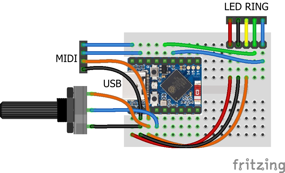
  • Breadboard and jumper wires.

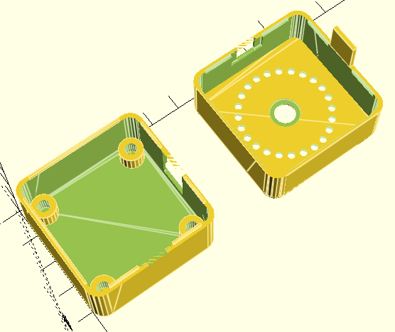
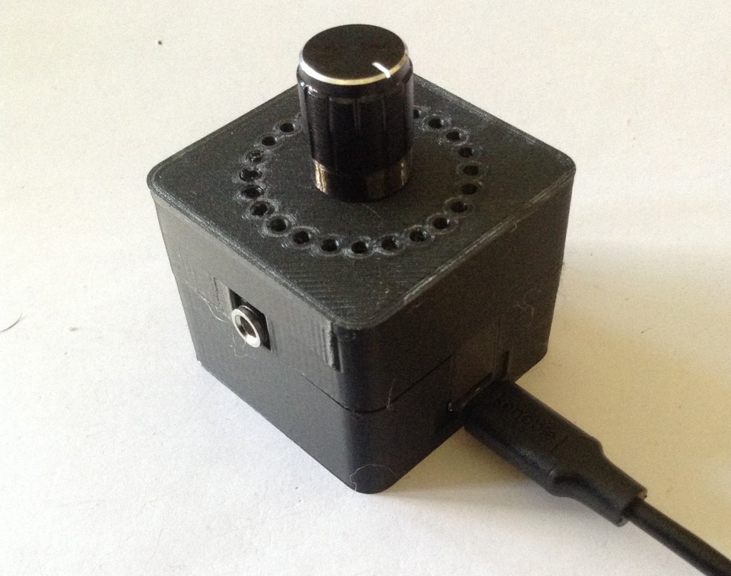
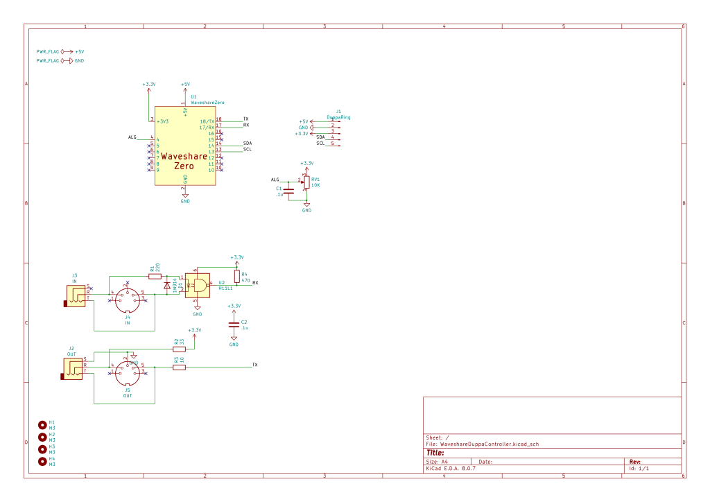
Waveshare Zero, Duppa LED Ring, Potentiometers

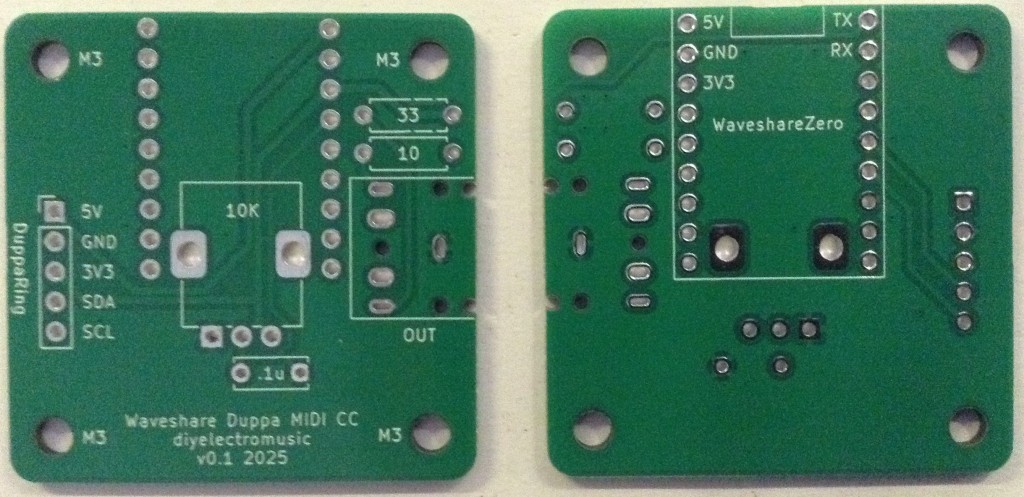
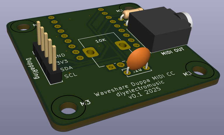
I’m planning on being able to use any Waveshare Zero format board that I have (so that includes ESP32-S3, ESP32-C3 and RP2040) with the Duppa Ring so that means finding common pins to support I2C.

From the various pinouts (see Waveshare Zero, Pimoroni Tiny, and Neopixels) I can see I can use two pins in the bottom right-hand (with the USB connector at the top) corner of the board.

I’ll also need an analog connection and potentially connecting RX/TX to MIDI.

The various pins I’ll be using are as follows:

PinFunctionESP32-S3ESP32-C3RP204015V2GND33V34ADCGP1GP0GP29/A313SCLGP10GP9GP514SDAGP11GP10GP417RXGP44GP20GP118TXGP43GP21GP0

Note, I’m not using physical pins 11 and 12, even though they also support I2C, as for the RP2040, these are on I2C bus 1, not 0 (see note later).

As the Pimoroni Tiny2040 is largely compatible too, that could also be used, but it will be physical pins 11 and 12, corresponding to GP5 and GP4, and 15 and 16 for GP1, GP0 (RX,TX).

The LEDs on the LED ring are powered from 5V, which comes directly off the Waveshare Zero USB port. The logic “VIO” is powered from 3V3.

The Code

I2C LED Ring

As the I2C pins to be used are configurable, this means changing the Duppa example code (and any other Arduino code) to initialise the I2C bus on specific pins as follows:

Wire.begin(11,10);    // SDA, SCL for ESP32-S3
Wire.begin(10,9); // SDA, SCL for ESP32-C3

Using the ESP32 Arduino Core, there is a specific board entry for the Waveshare Zero ESP32-S3. There isn’t one for the ESP32-C3 so I just used “ESP32C3 Dev Module”.

I used the Arduino core for RP2040 from here rather than the official core: https://github.com/earlephilhower/arduino-pico

But the I2C initialisation is a little different.

  Wire.setSDA(4);
Wire.setSCL(5);
Wire.begin();

If I’d have been using GP6 and GP7, then these would have required the initialisation of Wire1 rather than Wire with the RP2040 core.

Note: to use the serial port once a sketch has been loaded onto the board, requires the following to be set (via the Arduino Tools menu):

USB CDC On Boot -> Enabled

Once again, I’ve soldered the jumpers on the LED ring to enable pull-ups and set the address for S1 and S5, so that has to be changed in the demo code too.

Analog Potentiometer

In terms of analog read, the ESP32 has a resolution of 0..4095 compared to the Arduino’s 0..1023, so that has to be taken into account when calculating the MIDI CC values.

To do this, the reading has to be divided by the ratio of Pot Range / 128.

int newpot = algpot.avgeAnalogRead(PIN_ALG) / ((MAX_POT_VALUE+1)/128);

Serial MIDI

For these boards, the serial port has to be specified. There are different options depending on the board being used (more here).

To use the pins nominally designated as RX/TX on all of these boards, use:

// ESP32-S3 GP43,GP44 or ESP32-C3 GP20,GP21
MIDI_CREATE_INSTANCE(HardwareSerial, Serial0, MIDI);
// RP2040 GP1,GP0
MIDI_CREATE_INSTANCE(HardwareSerial, Serial1, MIDI);

It is a quirk of the RP2040 Arduino core that UART0 appears on Serial1 and UART1 on Serial2. Serial0 does not exist but USB is Serial (more here).

Also, for the RP2040 the pins can be changed prior to calling MIDI.begin() if required as follows:

Serial1.setRX(rxpin);
Serial1.setTX(txpin);
MIDI.begin();

MIDI USB

I want to make this a fairly stand-alone MIDI USB device, so for the ESP32 and RP2040 this means using the TinyUSB stack. There is an Adafruit library for Arduino that supports both and also works with the Arduino MIDI Library. References:

I’ve cribbed most of the code from: https://github.com/adafruit/Adafruit_TinyUSB_Arduino/blob/master/examples/MIDI/midi_test/midi_test.ino

And added the appropriate parts to my own midiSetup() and midiLoop() functions.

MIDI USB – ESP32-S3

For this to work on the ESP32-S3, the board settings (via the Arduino Tools menu) need to be changed as follows:

USB CDC On Boot -> Enabled
USB Mode -> USB-OTG (TinyUSB)
USB Firmware MSC On Boot=Disabled
USB DFU On Boot=Disabled

Naturally this means USB can’t be used for serial output anymore.

It also means that automatic sketch reset and download often didn’t work for me. It was quite normal to now have to use the BOOT and RESET buttons to get the ESP32 back into listening for a new sketch – not always, but also not uncommon. But this might be some serial port remapping weirdness that often occurs when the USB stack is running on the same microprocessor as the main code…

MIDI USB – RP2040

For the RP2040, the USB stack needs to be changed from the Pico SDK to TinyUSB, so in the Tools menu:

USB Stack -> Adafruit TinyUSB

There are some other RP2040 specific notes here, but I don’t believe they apply unless one is interested in rebuilding the core, default TinyUSB support directly.

USB MIDI – ESP32-C3

I don’t believe USB MIDI works on the ESP32-C3

Adafruit TinyUSB doesn’t seem to anyway and I haven’t looked into what the options might be yet.

Other Notes

I’ve left in all the conditional compilation from Duppa I2C MIDI Controller – Part 3 but for now am just working with potentiometer control.

Pretty much everything is configurable, but the most important config option is to specify the board at the top:

//#define WAVESHARE_ESP32S3
//#define WAVESHARE_ESP32C3
#define WAVESHARE_RP2040

I could probably auto detect from the build settings but for now, this will do.

Other options include GPIO pins, whether to include serial or USB MIDI (or both), and whether to enable MIDI THRU or not.

Find it on GitHub here.

Closing Thoughts

This is the first go at getting my Duppa controller working on 3V3 Waveshare Zero format boards, and so far it looks pretty good.

For the ESP32-S3 and RP2040 being able to enable MIDI USB is particularly useful. I might see if I can support MIDI THRU across the interfaces, which might be handy for a built-in USB to serial MIDI converter, but for now MIDI THRU is on the same port only.

I’ve not tested this with encoders or the endless potentiometer, but in theory it ought to work. I’d have to add some conditional compilation for GPIO numbers if I want to keep the same physical pins again.

Kevin

#controlChange #duppa #endlessPotentiometer #esp32c3 #ESP32s3 #i2c #midi #potentiometer #rgbLed #rotaryEncoder #rp2040 #WaveshareZero

Client Info

Server: https://mastodon.social
Version: 2025.04
Repository: https://github.com/cyevgeniy/lmst