I KISSed my Antenna – Here’s Why …
Many years ago I learned about a design technique called KISS. It was an acronym for “Keep It Sweet and Simple”. Somewhere along life’s journey I started seeing the acronym change to the rather offensive “Keep It Simple Stupid” which I entirely dislike. There are many sound reasons for simplifying a design but none of them imply a lack of intelligence on the part of the designer. Designs evolve and, in the process, become very complicated to the point where the probability of failure becomes critical.
A case in point is the Saturn V rocket that first took astronauts to the Moon. If I recall correctly, the Saturn V had something like 10 million components. If each component had been designed so that it had a 1 in 10 million chance of failure, the rocket would probably have failed at every launch. The reason is straightforward – failure probabilities in a complex machine are additive.
Every mistake is a learning opportunity. The designers of early rockets were certainly not stupid, but their rockets exploded on the launchpad, or during the early phases of launch. Even when rocketry had advanced sufficiently to repeatedly land men on the Moon, terrible disasters still happened.
There is a temptation to be so focused on an objective that errors slip into the design. Reviewing my own antennas, many of which have been featured in this blog, and the feedback I have received from some very knowledgeable Ham Radio Outside the Box followers, caused me to stop and re-think my designs. Every antenna discussed here in this blog has worked, meaning I have personally made contacts with each and every one of them. But, at the same time, some of the designs had flaws caused by too narrow a focus on end objectives. So, I made a decision to adopt a KISS approach.
These are my principle objectives based on my personal interest in operating backpack portable out in the Big Blue Sky Shack:
- Rapid deployment – an antenna must be ready to transmit as quickly as possible upon arrival at an operating site.
- Field expedient – An antenna must be specifically designed and constructed for temporary field operation. This necessarily implies that efficiency is not the prime objective. A “compromise” antenna is acceptable if it works well enough to make contacts.
- A small footprint – the entire station should occupy as small a footprint as possible, keeping in mind that many operating sites are in public spaces where other people may be present.
- Ham-made, meaning I don’t buy commercial antennas. I prefer antennas I have constructed myself. It saves money and allows more scope for experimentation.
- Stealthy – the mission objective is to make contacts, not educate curious people passing by. Ham radio equipment may look suspicious to some people; better to look inconspicuous and not be noticed.
- Self-contained – the antenna must not be dependent on anything I didn’t bring with me. This includes trees, vehicles or any other kind of antenna support.
- Everything must fit in, or on, a backpack that is sufficiently lightweight to be hiked into a remote operating site, or transported using a wheeled cart.
- Ancillary equipment, any chairs, tables, shelter, spare cables, spare battery, water and food must be part of the backpack portable package.
Softly, softly, catchee monkey
The “Stealthy” objective may sound unfriendly but it is very practical, especially when working a pile-up as is often the case with POTA. If somebody stops to ask questions I give them a very simple, but polite explanation. Usually they are just curious with no particular interest in ham radio. I was set up in a local park recently and had just completed a POTA activation when an official Ontario Parks vehicle pulled up in front of me. A young park warden got out and came over to ask me what I was doing. She told me she saw my big whip antenna and wondered what it was for and seemed interested when I told her I was contacting people by radio using Morse Code. She asked me how long I had been doing this. I was tempted to reply “oh, only about a half hour” but I overcame my frivolous inner self and replied “25 years”.
And another consideration; CW ops have a stealth advantage over phone ops – our operation is silent if we wear headphones – or ear buds which look less suspicious. If they can’t hear me they are more likely to pass on by. “He must be tracking wildlife, or something, best not to disturb him”.
It’s okay to be an ambassador for the hobby, that’s what Field Day is for. If it’s a quiet day on the bands I might be happy to have a nice conversation with a passer-by, but when the ether is overflowing with chasers and hunters the focus is on the mission’s prime directive.
We gotta get out of this place
There are many reasons for wanting a rapidly deployable portable rig. Out in the great outdoors the weather can change suddenly necessitating a fast teardown of antenna and radio. In a public space – such as a park – other people may gather in close proximity to our operation creating a disturbance or becoming susceptible to tripping over wires or being electrically excited by the high voltage at the end of a wire. In the backcountry there is also the possibility of a representative of the ursus americanus community paying us a visit. For these reasons, among others, having a portable rig that can be set up, or moved, in a couple of minutes is a great advantage.
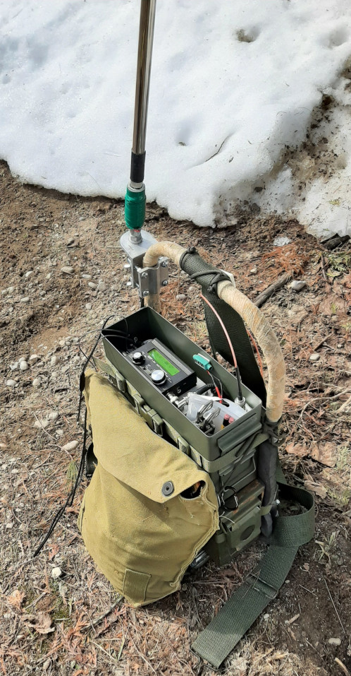
All these factors led me to build and deploy many of the antennas described in this blog. One in particular has led to a lot of discussion – the Coil-Loaded End-Fed Half-Wave (CLEFHW). This antenna comprises an 18.5ft telescopic stainless steel whip with a small loading coil at the base and a very short (0.05 wavelength) counterpoise.
What is “Electrical Length”
I made the claim that the loading coil changes the physical length from 18.5ft to an electrical length of a half wavelength on the 20m band. The choice of words is very important here. The physical length is measured in feet but the electrical length is measured in wavelengths.
Wikipedia defines electrical length thus:
In electrical engineering, electrical length is a dimensionless parameter equal to the physical length of an electrical conductor such as a cable or wire, divided by the wavelength of alternating current at a given frequency traveling through the conductor. In other words, it is the length of the conductor measured in wavelengths.
The purpose of the design was to eliminate long radial wires laying on the ground. A very short length of coax terminated in a common mode current choke acts as sufficient counterpoise. I wrote once before about a nice lady who stopped by to inquire, in a friendly manner, what I was doing. I was using a different antenna at the time and cautioned her to be careful of the wires on the ground. She responded by entertaining me with a little dance as she attempted to avoid stepping on them. Wires on ground in public spaces – ungood!
Another design objective of the CLEFHW was to be integral with a self-contained backpack kit occupying a ground footprint of only a couple of square feet. The backpack rig is its own operating table, so dump it on the ground, erect self-contained antenna, transmit. If I didn’t have worn out knees I wouldn’t even need a chair, but I did have to add an ingenious collapsible plastic stool to the kit.
Time for confessions
Now it’s mea culpa time … while the CLEFHW has performed successfully in more than one POTA activation and numerous casual QSOs, it does have a couple of design flaws. First, the biggest and baddest. A full-size vertical EFHW has a current maximum point half way up the antenna, far away from the power gobbling greedy green ground. But the CLEFHW cheats; it is not a physical half wavelength long, it is an electrical half wavelength long so the current maximum point remains at the base of the antenna. That results in high radiation around about head height. I checked with the ARRL RF exposure calculator and found that shouldn’t fry too many brain cells while operating at QRP levels. Proximity to ground also increases power loss. I mitigated this loss by raising the base of the antenna to about 1 meter above the terra firma. A few hundred milliwatts may still slip away to warm the worms, but heck, that’s the fun of QRP, so they say.
Another, shall we call it flaw, is the double impedance conversion. An email correspondent whose views I much respect advised me to think of loading coils as impedance matching devices. Using that way of thinking the CLEFHW’s loading coil converts the impedance of the whip to an R+jX value resembling that of a full-length EFHW. The 49:1 impedance transformer then reduces the impedance down close to 50+j0. There is almost certainly some inefficiency in that double transition. But, one of the design parameters already listed calls for Field Expedience above efficiency so I guess there is no free ride here. As somebody else once said: “every antenna is a compromise”.
The big, overriding objective of the CLEFHW design was to work as an integral element of a backpackable, rapid deployment portable ham radio kit. Despite some unusual quirks in its conception it gets the job done. Is it overly complex? Does the bizarre double impedance conversion cause more chaos than a monkey in a china shop? Should I abandon the design based on its assault on sound antenna physics? I seriously considered scrapping the project in favor of a Sweet and Simple tunable whip, but I am uncertain whether that would be an improvement.
The direction in which I am heading at the moment is to replace the 49:1 transformer with an L-match “tuner”, that is capable of dealing with the vagaries of terrain I experience in my itinerant portable operations. Despite widespread opinions describing End-Fed Half-Wave antennas in less than flattering language, the advantages for a portable operator outweigh any negatives so future endeavors will remain on that course.
As always, your feedback is much appreciated.
Help support HamRadioOutsidetheBox
No “tip-jar”, “buy me a coffee”, Patreon, or Amazon links here. I enjoy my hobby and I enjoy writing about it. If you would like to support this blog please follow/subscribe using the link at the bottom of my home page, or like, comment (links at the bottom of each post), repost or share links to my posts on social media. If you would like to email me directly you will find my email address on my QRZ.com page. Thank you!
The following copyright notice applies to all content on this blog.
This work is licensed under a Creative Commons Attribution-NonCommercial-NoDerivatives 4.0 International License.
#AmateurRadio #Antennas #CLEFHW #Counterpoise #CW #OutdoorOps #Portable #POTA