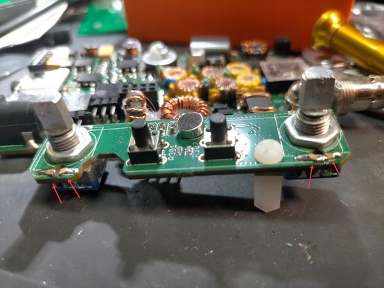
#happy #captainpicardday #picardday #jeanlucpicard #picard #startrek #thenextgeneration #generations #firstcontact #insurrection #nemesis #startrekpicard #startrek58 #actionfigures #qmx #macfarlanetoys @trekcore
#QMX
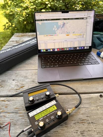
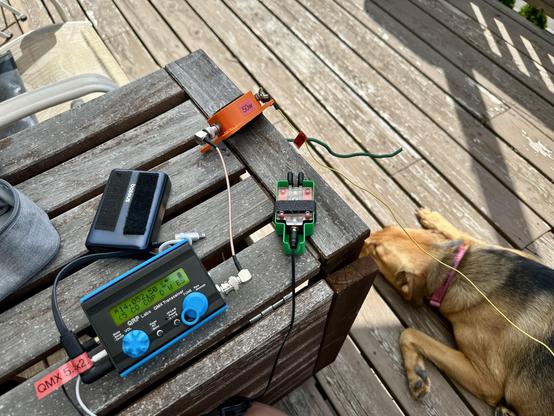
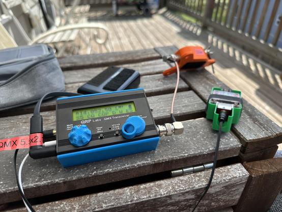
Just playing with QRP labs radios today. Vertical MC-750, 3-4W and 20m got a good reach even the sun is throwing tantrums.
First time listened the QMX SSB and it sounds really nice!
#qrp #qrplabs #qmx #qcx #mc750 #chelegance #hamradio #amateurradio
My radio is tiny. So why is my POTA backpack so heavy?
We have mountains in Ontario. We call them mountains, but they are really just small hills. So I have never had to actually hike for miles up steep slopes carrying a backpack with all my radio gear, plus anything else I might need for a mountaintop activation. To all those who operate in this fashion, you have my sincere admiration.
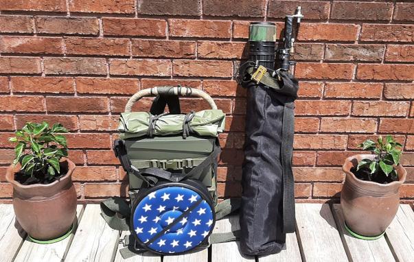
VA3KOT’s POTA kit packed and ready to go.Get your kicks on fourteen zero six
At the other end of the scale we have what has been called PLOTA (Parking Lots On The Air) activators. These operators perform their activations while sitting in their vehicles. It is tempting to think they probably grab their morning coffee at the a drive-thru en route to the activation. I confess that I have done this too, but only when the temperature drops down to double digits with a minus sign in front. I imagine that, in southern states, when it gets hot enough to cook eggs on the sidewalk, operating in air-conditioned comfort is almost a necessity. If this style of operating works for you, or is necessary in your environment, then you are doing your part to keep outdoor radio operations alive and thriving.
Mr Blue Sky
In between hiking up an inhospitable mountain, exposed to the elements, and being welded to a car seat is another option. Maybe this is the true expression of operating outdoors – leaving your vehicle and carrying your station into the back country, or even a local park. This is my personal choice. It combines a love of the great outdoors with a love of radio – what I have dubbed operating in the Big Blue Sky Shack.
There are options even within that. Do you carry your gear from your vehicle to the nearest picnic table, or do you backpack everything you need (seat and table included) down a trail, blatting the bugs that are intent on drinking your blood, admiring the wildlife while avoiding large mammals intent on eating you, to find a clearing in the trees where you can set up.
Oh Yuck!
Let me tell you a story about picnic tables that may discourage you from regarding them as a comfortable, convenient place to operate. I used to be an RV camper; it was fun but for several reasons I eventually sold my trailer. During one camping trip a neighboring camper was packing up his giant fifth wheel. I watched as he laid his sewage hose out to dry on a picnic table. For those who have never owned an RV (or caravan as it is known in many parts of the world), a sewage hose is used for emptying the contents of the “black tank” at the “dump station” on the way out of the campground. But I am sure you always use a plastic table cloth, don’t you? Well consider this, your table cloth is going to pick up millions of bacteria from the picnic table surface and transfer them to your food. Yuck!
Little boxes
Going back to the supremely fit, energetic types who climb real mountains to operate. They tend to carry extremely lightweight radios; often the whole station packs away into a tough, rugged plastic case that slips into the pocket of a backpack. I have often thought of emulating this idea. But instead, not being quite as fit as I could be, and with age-related physical limitations, I have chosen a different approach. My backpack station is a little on the heavy side (not to be confused with the Heaviside which is a layer of the ionosphere that makes our hobby possible).
Say, friend, I got a heavy load
At the heart of it all is a QRP-Labs QMX transceiver. This tiny device is so light it almost defies gravity – but it is not a complete portable radio station. So I built a backpack frame that can carry everything I need – and it is surprising what that includes when you can’t pop back to your vehicle to grab something else. Here is a list of what I carry:
- Transceiver – QRP-Labs QMX (low band version)
- Talentcell 6500 mAh LiFePo4 battery
- Drok buck converter to regulate the voltage fed to the transceiver
- Putikeeg CW paddle key
- Earbuds
- Ham made line isolator (common mode current choke)
- Selection of RG-316 coax cables
- Rite in the Rain log book, pencils
- UTC wristwatch
- Reading glasses
- Selection of wire antennas and radials
- 18.5ft telescoping stainless steel whip
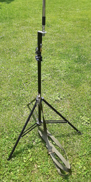
- Lightweight tripod for supporting the whip on rocky ground
- Spiderbeam 7m telescoping fiberglass pole
- Telescoping plastic seat
- Multitool
- Small tarp
- Selection of cordage
Of course there are even more things that must be carried such as water, bug spray, snacks etc. Those little hardened plastic boxes with a tiny radio, key and wire antenna are impressive to behold, but they are not a complete and independent station incorporating everything needed for personal comfort and survival far from shelter and the means of egress.
Experience has taught me not to rely on commercial backpacks to carry all my gear. Most are intended to carry the typical range of items needed by a hiker. I bought a rugged, military style, cotton canvas backpack from a local supplier and was disappointed when I tried to use it to carry my radio equipment. There was no padding, no frame; it was very uncomfortable to carry. Clearly it was made for lighter, softer loads than mine.
Another alternative is real backpacks made for the military. They are built tough but are also very tough on the budget. I just couldn’t justify spending many times more on a backpack than the radio equipment inside it.
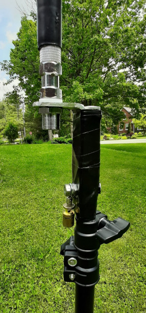
Custom antenna bracket secured with a quarter inch nut and bolt – and Gorilla tape! Note the radial attachment point.Just in case
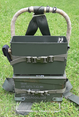
The solution involved a little bit of work in my garage workshop using many items I had already hoarded ready for future project ideas. I had to purchase two 30-cal steel ammo cases, but they were very inexpensive. One was sold for storing hunting ammunition, but the other was a bona-fide military surplus case with markings indicating it was intended for storing 200 cartridges of 7.62mm rounds and other items. I plan to repaint it sometime before it gets me into trouble. Why steel ammo cases? They are built tough for protecting delicate equipment, they are cheap, and they provide sufficient heft to create a firm operating platform.
Vertically stacked cases are the right height for field operations while the operator is seated on a camping stool.Both steel cases are stacked vertically on a modified aluminum backpack frame. The bottom case holds antennas, cables etc. The top case holds radio, battery, key etc. Everything is pre-assembled inside the radio case – just pop the lid, insert the earbuds, turn on, tune in and go.
Telescoping plastic stool from AmazonMy Putikeeg CW key has very strong magnets on its base and holds very securely to the steel case. I use it in vertical fashion, with the paddles peeking up above the rim of the steel case. The assembly sits at a very comfortable height for operating the radio without the need for a table. My seat is a lightweight, plastic, telescoping thing with a padded cushion on top. It is an ingenious design with many latches holding it up. I was very cautious about trusting my posterior atop this perch at first, but it supports my weight just fine. The pictures tell a lot more than many more words can convey.
Whatever style of outdoor operating you prefer you are helping keep amateur radio alive. This post describes the way I operate and is not meant to be judgemental about any other style. There is room enough in our hobby for whatever way you like to operate. In fact, I invite you to comment or send me a description of your outdoor radio equipment – even if it is mounted on a set of four wheels 😉
All tuned up on fourteen zero six. The antenna connects to the BNC on the right. The Putikeeg paddles are secured by strong magnets. Earbuds are on the right. Beneath the radio are the 6500 mAh LFP battery, Drok buck voltage regulator and a line isolator.My POTA gear is constantly evolving so what you see and read here may not be what you see if we meet on a trail sometime. I like to experiment and try out different ideas. Some call me nuts; maybe they are right but I’m having fun.
Help support HamRadioOutsidetheBox
No “tip-jar”, “buy me a coffee”, Patreon, or Amazon links here. I enjoy my hobby and I enjoy writing about it. If you would like to support this blog please follow/subscribe using the link at the bottom of my home page, or like, comment (links at the bottom of each post), repost or share links to my posts on social media. If you would like to email me directly you will find my email address on my QRZ.com page. Thank you!
The following copyright notice applies to all content on this blog.
This work is licensed under a Creative Commons Attribution-NonCommercial-NoDerivatives 4.0 International License.
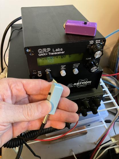
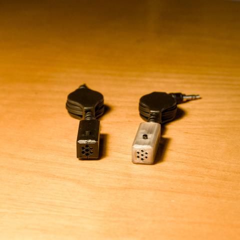
Mic in purple so I can get appropriately funky in QRP SSB. Now I have to get serious about updating the QMX+ firmware to add SSB functionality.
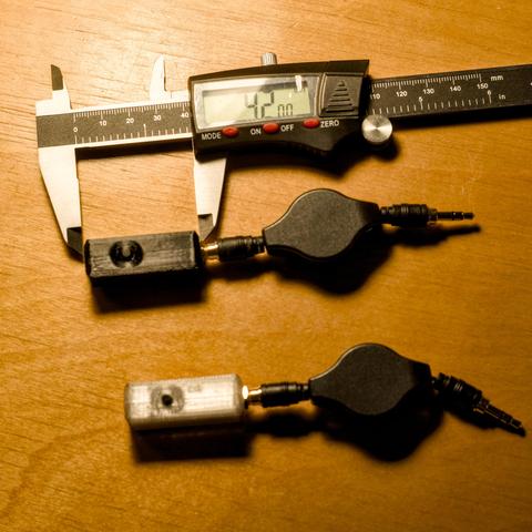
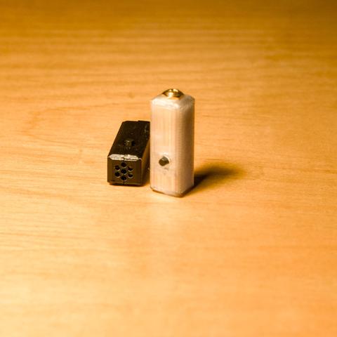
These two *little* mics were printed and assembled by AD7OV based on the K6ARK plan...so close to cost that it's being allowed under the non-commercial CC license 😂. Info is in the https://groups.io/g/QRPLabs archives.
3D model: https://www.printables.com/model/320559-mini-microphone-for-qmx-trusdx-usdx-kx2-and-kx3
#prince #QMX #3dprint #SSB #QRP #microphones #RigPix #KeepSSBfunky
@bgarfoot if I can have only one, then it must do everything.
The IC-705 never appealed to me but the #ftx1 does.
If I can bring along an HT, then I would opt for the #lab599 #tx500 because of its ruggedness, and it being light weight and having a very low RX current draw.
If I want to go realy light weight, I grab the #qrplabs #qmx. Very high quality radio for small a price.
#hamradio #radioamateur
Beta firmware for #QMX transceivers. It should now better works in SSB. Very interesting video :
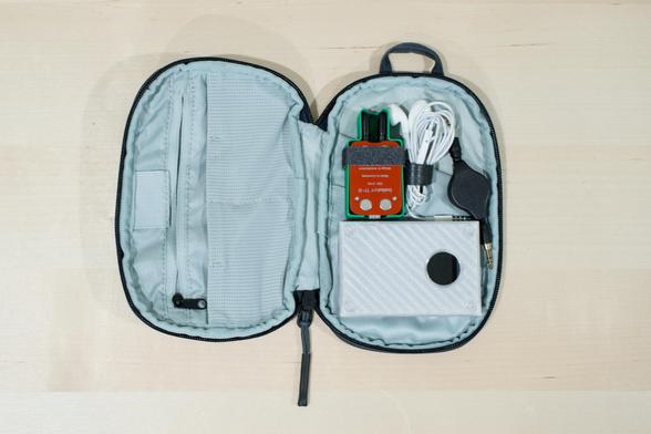
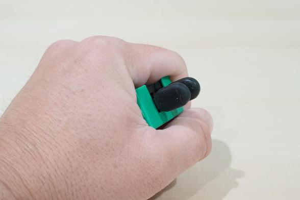
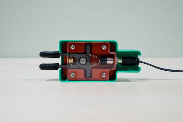
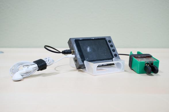
Just finished building my #CW practice kit. Also nicely turns into my #POTA / #SOTA travel kit for CW. I designed the cases for the BaMaTech - BaMaKeY TP-III and the HAMCUBE Mini so that they provide more ergonomics and comfort while in use.
Whatcha think?
#bamatech #bamatechtpiii #cwmorse #hamradio #amateurradio #radio #icom #yaesu #qmx
Made some micrphones for my #qmx setup. I think Josh KI6NAZ is going to make the same ones tonight! Many thanks to Adam Kimmerly for designing these and allowing a ludite like me to make them at home! I figured I'd make 2 just in case one was a dud! All good though, both work! #pota #sota #qrp #hamradio #amateurradio
https://www.printables.com/model/320559-mini-microphone-for-qmx-trusdx-usdx-kx2-and-kx3
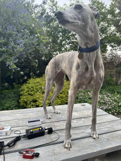
Finally got round to getting acquainted with my #QRPLabs #qmx. For reasons known only to her, Pippi the #whippet has decided to get involved and is currently “helping”.
#AmateurRadio #HamRadio #dogsofmastodon
EFHW matching: 49:1 Impedance Transformer or L-Network?
What is the best way to match the very high impedance of an End-Fed Half-Wave antenna to the 50 ohm impedance of a transceiver? There are various ways to do this but this week’s post is going to focus on just two – a 49:1 impedance transformer (or UNUN if you prefer) and an L-network.
We are dealing with QRP devices but the same issues arise with QRO devices. In fact some of the complexities may be exacerbated at higher power – especially core overheating.
49:1 impedance transformer
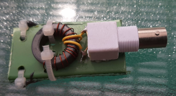
QRP 49:1 impedance transformer. Note the separate primary and secondary windingsThis is by far the most widely used matching device but many claim it is inefficient. I have used an “Outside the Box” winding method that I have seen described as “Fuchs style”. The primary and secondary windings are entirely separate instead of being twisted together. This method isolates the windings and is said to prevent static from traveling back down the coax to damage the transceiver. But it also requires a separate 0.05WL counterpoise connected to the bottom of the secondary winding.
Pros
- Broadband operation
- Easy to construct
- No calculations needed
Cons
- Lower efficiency claimed
- Can be used on even harmonics but the antenna is only a half-wave on its fundamental frequency
- Potential for losses due to core overheating
- Leakage flux due to poor coupling between windings
- May require capacitance across primary and/or secondary to compensate
L-network
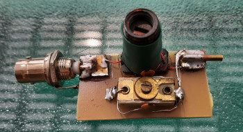
QRP L-network featuring both a variable inductor and variable capacitorSome claim that an L-network is more efficient than an impedance transformer. While I don’t dispute the claim I would respond “show me the math”. An L-network is usually constructed from a fixed value serial inductor and a fixed value parallel capacitor (although there are other topologies depending on the matching parameters involved). I built one using a slug-tuned variable inductor and a ceramic trimmer capacitor.
Pros
- Higher efficiency claimed
- Easy to construct
- Avoids complex issues with transformer cores and winding coupling
Cons
- Single band only
- Calculations required to establish correct values of L and C
The Ham Radio Outside the Box laboratory (a grand name for my basement workbench) has built many 49:1 impedance transformers for both QRP and QRO operation. The QRP units are deployed in backpack portable operations and the QRO units have seen service both in the field and in the home shack. Both the conventional “twisted” coupling method and separate windings have been used.
Which winding method is best?
One of the issues with 49:1 transformers is “leakage flux” which means not all of the energy in the primary winding is coupled to the secondary. The conventional winding method is to twist the first two turns of the primary and secondary together to improve coupling. The remaining turns are only coupled to the primary by the flux in the core. Furthermore, there is often a “crossover” turn to bring the far end of the secondary out on the opposite side of the core from the primary. This may further reduce the coupling efficiency.
An alternative method is to wind the secondary, without a crossover turn, around the core. The separate primary is then wound around the center of the secondary. Should the secondary be spread around the core, or closely spaced? Opinions vary on this. I now favor keeping the secondary turns closely spaced. The reason? A closely spaced secondary winding should improve inter-winding coupling and reduce leakage flux.
What about the turns ratio?
Should it be 49:1, 64:1 or …? There is an easy answer to that: just divide your antenna impedance by 50 and bingo, there’s your answer. Oh, but what is the impedance of your antenna, 2000 ohms, 2319.647 ohms, 3000 ohms? We don’t actually know and it may vary depending on how the antenna wire is erected (which for portable operators may be different every time). A ratio of 49:1 provides a good enough match to most every value of End-Fed Half-Wave (and multiples) we are likely to experience.
Or just build an L-network!
We have seen that 49:1 impedance transformers have many variables that impact efficiency. Leakage flux has been discussed so it is relevant to note that placing a small capacitor (typically 100pF) across the primary winding is recommended to somehow compensate. Conventional 49:1 transformers are wound as autotransformers, so we have a series inductor between the antenna and the radio, and a parallel capacitor. Doesn’t that sound very similar to one of the topologies of an L-network?
My initial experiments with building L-networks involved a fixed series coil and a parallel capacitance made from a short length of thin coax – like RG-174. I experienced the problem that the calculated values of L and C did not provide the best possible match to 50 ohms. I still needed a “touch-up” tuner to bring the SWR down to a safe level for my QRP Labs QMX transceiver. I realized that a field portable antenna was going to need slightly different component values depending on whether my temporary station was setup on exposed ancient bedrock, or over the moist ground at the edge of one of the Great Lakes. What I needed was an L-match “tuner”, i.e. an L-network with variable inductors and capacitors.
42 years ago …
A long, long time ago (42 years to be precise) I was a penniless SWL foraging for food in the forest – alright that’s an exaggeration, but I had a young family and couldn’t spare the cash to buy a decent shortwave receiver. A friend told me about a design in Practical Wireless magazine for a shortwave converter that would work with a regular domestic AM receiver. I had the components shipped over from the recommended UK suppliers and built the converter. It worked splendidly and I spent many happy hours listening to the busy shortwave bands. Then I became fabulously wealthy (i.e. I could at last afford shoes and to eat every day of the week), bought a real HF radio and the converter was relegated to the back of a closet.
The point of the story is that I was able to scavenge that converter for the components I needed to build an L-match for an End-Fed Half-Wave antenna. The inductor shown in the picture above is wound over an adjustable slug-type ferrite core of unknown mix. The capacitor is a ceramic trimmer with a couple of fixed ceramic capacitors in parallel to bring its value into the range that was needed. The only comment I can make on the efficiency of that unknown core is that it didn’t get hot (or even warm) after an extended period of transmitting at 5 watts. Tuning is quite sharp but I was able to get a 1.5:1 SWR from my Shortened Sloping End-Fed Half-Wave antenna (see last week’s post). I probably could have obtained an even lower SWR by adjusting the length of the high Q top section of the SSEFHW.
QSO’s?
As a recent convert to L-networks I have only made enough QSOs to be countable on fingers and toes. On the other hand, over the years, I have made thousands of QSOs with a 49:1 impedance transformer. Both the devices shown in the pictures above accompany me on every field portable outing so I have options and can compare their performance.
Does it matter, really?
Sometimes I give my head a shake and tell myself to put the physics textbooks back on the shelf and just enjoy the experience of being out in the Big Blue Sky Shack with my radio. At other times, after calling CQ ’til the cows come home and getting no responses, I ponder the question of whether my antenna is doing its job or, as sailors used to say, is idly “swinging the lead”.
What are your experiences with either impedance transformers/UNUNs or L-networks? Your opinions are very welcome either by adding a comment below, or if you prefer, by email (QRZ.com).
Help support HamRadioOutsidetheBox
No “tip-jar”, “buy me a coffee”, Patreon, or Amazon links here. I enjoy my hobby and I enjoy writing about it. If you would like to support this blog please follow/subscribe using the link at the bottom of my home page, or like, comment (links at the bottom of each post), repost or share links to my posts on social media. If you would like to email me directly you will find my email address on my QRZ.com page. Thank you!
The following copyright notice applies to all content on this blog.
This work is licensed under a Creative Commons Attribution-NonCommercial-NoDerivatives 4.0 International License.
#AmateurRadio #Antennas #Counterpoise #OutdoorOps #Portable #QMX
SSEFHW – Another Shortened End-Fed Half-Wave Antenna for 20m
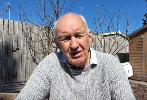
Peter Waters G3OJV Screen grab from YouTubeI was browsing through ham radio videos on YouTube recently as I often do (daily!) when I came across one from Peter Waters G3OJV on the Waters & Stanton video channel. The title of the video immediately caught my attention: “Shortened Vertical Half Wave Antenna”. End-fed antennas are a favorite of portable operators because of the ease with which they can be erected. End-Fed Half-Wave antennas have the added advantage of needing a counterpoise that is 5 times shorter than required by an End-Fed Random Wire.
Another attribute that is appealing to portable operators is a small station footprint, so a vertical antenna, combined with a very short counterpoise, results in a stealthier station that is less likely to interfere with other people using the same park or trail, or attract unwelcome attention.
I achieved this already with the 20m CLEFHW (Coil-Loaded End-Fed Half-Wave) which has performed very well, although it has also attracted consternation from antenna physics experts. Sometimes we just have to shrug and accept the principal that “if it works, it works” and move on.
When I watched Peter’s video I realized I had overlooked another very simple way of shortening a half-wave antenna. Peter took a commercial helically loaded quarter-wave antenna and put it at the top of a pole. Beneath it he connected a full-length quarter-wave wire to create an electrical half-wave fed at the bottom through a 49:1 impedance transformer.
I realized I had used this technique once before to fit an 80m EFHW into the restricted space of a campsite. I built a 40m EFHW, added a coil and then a short pigtail wire. The 40m EFHW comprised one half of an 80m EFHW while the coil and short pigtail made up the other half. Yes, it was a compromise with lower efficiency than a full-length 80m EFHW but it got me into my weekly CW rag chew with friends who are often over a hundred miles away when I am traveling.
SSEFHW (Shortened Sloping EFHW) version 1A Shortened Sloping End-Fed Half-Wave antenna
I built the G3OJV shortened EFHW for 20m using the same loading coil I had built for the CLEFHW with a 57-inch whip from an old hamstick as the radiating element. A 17ft wire was added below it to make up the other half of a 20m EFHW. It worked – well to be precise, I made contacts with it using just 5 watts.
I did make one change to the G3OJV design. The whip, loading coil and mounting arrangement are a little too heavy for my 29ft fiberglass pole (a damaged MFJ 33ft pole repaired with sections of a Crappie fishing pole). So I erected a kludge pole that was only 15ft tall and routed the bottom wire out an angle to a point a few feet away from the pole. This resulted in a strong front-to-back gain ratio at elevation angles above 35 degrees, but also, unfortunately, expanded the footprint on the ground. From my QTH in southern Ontario, the front-to-back ratio is an advantage since most of my contacts are to the south. I point my wire at Texas to cover most of CONUS.
But, this arrangement resulted in a set of gear that is not very convenient to carry down a trail. I had to come up with a better idea. So I built SSEFHW version 2.
SSEFHW version 2SSEFHW version 2 is a Shortened Sloping EFHW made entirely of one single length of 26ga silicone coated wire, wound around a short section of 2-inch diameter PVC built-in vacuum cleaner pipe, 57 inches from one end. Approximately 28 feet of wire was used in its construction.
The coil section is approximately 7.7 microhenries to match the original heavier coil used in version 1. The whole antenna is so light it almost defies gravity and fits in a small plastic freezer bag.
Another kludge 17ft pole was made from the remains of two 13ft Crappie poles (after being scavenged to repair my damaged MFJ pole) and a short piece of half-inch Schedule 40 PVC plumbing pipe. It all fits over, and is supported by, a driveway marker pole stuck in the ground.
You may notice the dramatic difference in weather between the two pictures taken only a day apart. The image to the right was electronically color enhanced to improve its contrast.
Side note: Kludge is cheap and cheerful but a Spiderbeam pole is now on order from Vibroplex. Spiderbeam poles, engineered in Germany, have a good reputation for strength and robustness. Ham Radio Outside the Box will review the product when it has been received.
SSEFHW with “Fuchs style” 49:1 transformerI was entirely unsure how Version 2 would perform and was pleasantly surprised when the SWR, measured using my RigExpert antenna analyzer, turned out to be 1.8:1 at the output of the 49:1 impedance transformer. That is already an acceptable SWR but, to preserve the legendary immortality of the PA transistors in my QRP Labs QMX transceiver, I added my “Old Barebones” ham-made Z-match and brought the SWR down further to 1.05:1.
Does it QSO?
No, absolutely not. I make the QSOs; the antenna is just a dumb bit of wire [smile]. My first contact using the SSEFHW was with a station in Kansas about 900 miles away. He gave me a 559 RST report and I received him at 599. Not bad for a QRP CW contact and typical of the kind of reports I have been receiving using other antennas. The SSEFHW (sounds like the name of a ship doesn’t it) can be supported by a pole, or even a low tree branch. My feeble throwing skills will not be overly challenged launching this antenna into a tree.
Ontario’s Bruce Peninsula (courtesy Open Street Map)Kudos where it belongs
I cannot claim originality for this antenna, that belongs to Peter Waters G3OJV. I simply massaged Peter’s idea to suit my own backpack portable operating style.
You will find me in remote clearings at the end of a trail on the Bruce Peninsula or elsewhere along the Niagara Escarpment.
Cliff edge operating site on the Georgian Bay coast of the Bruce Peninsula. The lake is 300 feet below the cliff edge. No parking here, in fact no road! This site is a 1km hike through black bear country.The Bruce Peninsula is approximately 100km long and forms part of the Niagara Escarpment which runs from Niagara Falls at the border between Ontario and New York State to Tobermory, Ontario at the top left of the map.
The west coast of the peninsula is bounded by Lake Huron while the east coast runs along Georgian Bay and comprises dramatic scenery with tall cliffs plunging down to the lake. With scenery like this who would want to sit inside a vehicle to play radio?
Help support HamRadioOutsidetheBox
No “tip-jar”, “buy me a coffee”, Patreon, or Amazon links here. I enjoy my hobby and I enjoy writing about it. If you would like to support this blog please follow/subscribe using the link at the bottom of my home page, or like, comment (links at the bottom of each post), repost or share links to my posts on social media. If you would like to email me directly you will find my email address on my QRZ.com page. Thank you!
The following copyright notice applies to all content on this blog.
This work is licensed under a Creative Commons Attribution-NonCommercial-NoDerivatives 4.0 International License.
@passthejoe #zbitx is not a good portable QRP radio until it has more efficient finals though. Over 30 watts in for less than 5 watts out!?! come on. You run down your batteries too fast, just to overheat the radio and its insufficient flat-plate heatsink. I added a fan to mine to try to cope with that. But yeah, the rest of it is pretty cool. As with most things, there are disadvantages to be an early adopter, that's all. I ordered a #qmx+ kit in the meantime; too bad it's not open source.
Played some radio, but oh boy am I unfit. 23km on the bicycle and I am absolutely shattered. How do people do 150km a day? Steroids?
https://youtu.be/g56AFGz2zhI?si=4XpkEy2KJRi5vx4_
#hamradio #amateurfunk #qmx
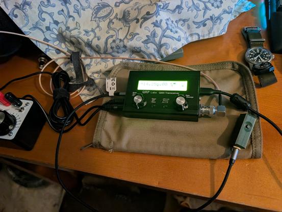
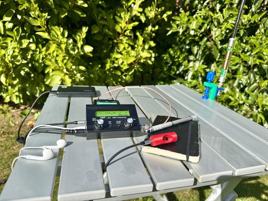
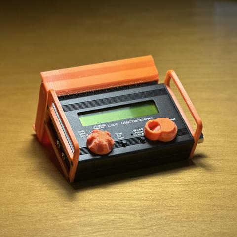
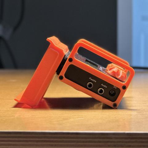
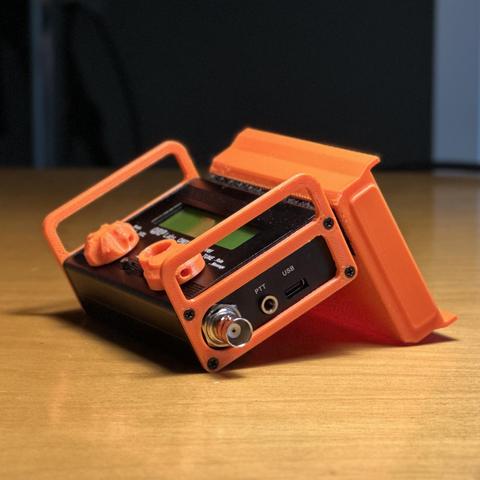
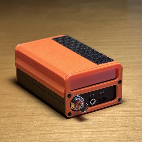
Received my #QMX and printed some bits and bobs to make it mine. My world consists of lots of Velcro and 3D Printed Goods :D What else should I print for this rad radio? #qrp #hamradio #amateurradio #sota #pota #3dprinting #3dprint #3dprinted #velcro

