#OutdoorOps

2025-06-11

My radio is tiny. So why is my POTA backpack so heavy?

We have mountains in Ontario. We call them mountains, but they are really just small hills. So I have never had to actually hike for miles up steep slopes carrying a backpack with all my radio gear, plus anything else I might need for a mountaintop activation. To all those who operate in this fashion, you have my sincere admiration.

VA3KOT’s POTA kit packed and ready to go.

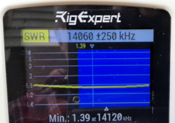
Get your kicks on fourteen zero six

At the other end of the scale we have what has been called PLOTA (Parking Lots On The Air) activators. These operators perform their activations while sitting in their vehicles. It is tempting to think they probably grab their morning coffee at the a drive-thru en route to the activation. I confess that I have done this too, but only when the temperature drops down to double digits with a minus sign in front. I imagine that, in southern states, when it gets hot enough to cook eggs on the sidewalk, operating in air-conditioned comfort is almost a necessity. If this style of operating works for you, or is necessary in your environment, then you are doing your part to keep outdoor radio operations alive and thriving.

Mr Blue Sky

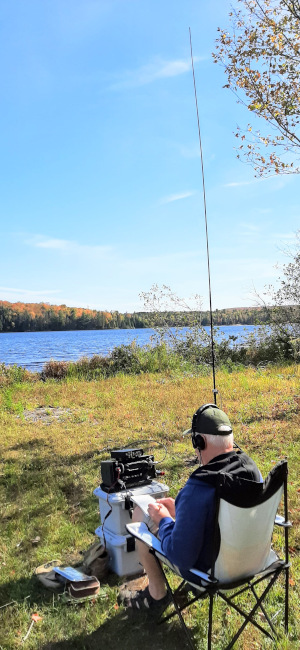
In between hiking up an inhospitable mountain, exposed to the elements, and being welded to a car seat is another option. Maybe this is the true expression of operating outdoors – leaving your vehicle and carrying your station into the back country, or even a local park. This is my personal choice. It combines a love of the great outdoors with a love of radio – what I have dubbed operating in the Big Blue Sky Shack.

There are options even within that. Do you carry your gear from your vehicle to the nearest picnic table, or do you backpack everything you need (seat and table included) down a trail, blatting the bugs that are intent on drinking your blood, admiring the wildlife while avoiding large mammals intent on eating you, to find a clearing in the trees where you can set up.

Oh Yuck!

Let me tell you a story about picnic tables that may discourage you from regarding them as a comfortable, convenient place to operate. I used to be an RV camper; it was fun but for several reasons I eventually sold my trailer. During one camping trip a neighboring camper was packing up his giant fifth wheel. I watched as he laid his sewage hose out to dry on a picnic table. For those who have never owned an RV (or caravan as it is known in many parts of the world), a sewage hose is used for emptying the contents of the “black tank” at the “dump station” on the way out of the campground. But I am sure you always use a plastic table cloth, don’t you? Well consider this, your table cloth is going to pick up millions of bacteria from the picnic table surface and transfer them to your food. Yuck!

Little boxes

Going back to the supremely fit, energetic types who climb real mountains to operate. They tend to carry extremely lightweight radios; often the whole station packs away into a tough, rugged plastic case that slips into the pocket of a backpack. I have often thought of emulating this idea. But instead, not being quite as fit as I could be, and with age-related physical limitations, I have chosen a different approach. My backpack station is a little on the heavy side (not to be confused with the Heaviside which is a layer of the ionosphere that makes our hobby possible).

Say, friend, I got a heavy load

At the heart of it all is a QRP-Labs QMX transceiver. This tiny device is so light it almost defies gravity – but it is not a complete portable radio station. So I built a backpack frame that can carry everything I need – and it is surprising what that includes when you can’t pop back to your vehicle to grab something else. Here is a list of what I carry:

  • Transceiver – QRP-Labs QMX (low band version)
  • Talentcell 6500 mAh LiFePo4 battery
  • Drok buck converter to regulate the voltage fed to the transceiver
  • Putikeeg CW paddle key
  • Earbuds
  • Ham made line isolator (common mode current choke)
  • Selection of RG-316 coax cables
  • Rite in the Rain log book, pencils
  • UTC wristwatch
  • Reading glasses
  • Selection of wire antennas and radials
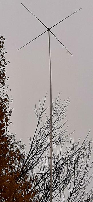
  • 18.5ft telescoping stainless steel whip
  • Lightweight tripod for supporting the whip on rocky ground
  • Spiderbeam 7m telescoping fiberglass pole
  • Telescoping plastic seat
  • Multitool
  • Small tarp
  • Selection of cordage
Modified lighting tripod – a bargain purchase at a charity store. Shoulder strap was added later.

Of course there are even more things that must be carried such as water, bug spray, snacks etc. Those little hardened plastic boxes with a tiny radio, key and wire antenna are impressive to behold, but they are not a complete and independent station incorporating everything needed for personal comfort and survival far from shelter and the means of egress.

Experience has taught me not to rely on commercial backpacks to carry all my gear. Most are intended to carry the typical range of items needed by a hiker. I bought a rugged, military style, cotton canvas backpack from a local supplier and was disappointed when I tried to use it to carry my radio equipment. There was no padding, no frame; it was very uncomfortable to carry. Clearly it was made for lighter, softer loads than mine.

Another alternative is real backpacks made for the military. They are built tough but are also very tough on the budget. I just couldn’t justify spending many times more on a backpack than the radio equipment inside it.

Custom antenna bracket secured with a quarter inch nut and bolt – and Gorilla tape! Note the radial attachment point.

Just in case

The solution involved a little bit of work in my garage workshop using many items I had already hoarded ready for future project ideas. I had to purchase two 30-cal steel ammo cases, but they were very inexpensive. One was sold for storing hunting ammunition, but the other was a bona-fide military surplus case with markings indicating it was intended for storing 200 cartridges of 7.62mm rounds and other items. I plan to repaint it sometime before it gets me into trouble. Why steel ammo cases? They are built tough for protecting delicate equipment, they are cheap, and they provide sufficient heft to create a firm operating platform.

Vertically stacked cases are the right height for field operations while the operator is seated on a camping stool.

Both steel cases are stacked vertically on a modified aluminum backpack frame. The bottom case holds antennas, cables etc. The top case holds radio, battery, key etc. Everything is pre-assembled inside the radio case – just pop the lid, insert the earbuds, turn on, tune in and go.

Telescoping plastic stool from Amazon

My Putikeeg CW key has very strong magnets on its base and holds very securely to the steel case. I use it in vertical fashion, with the paddles peeking up above the rim of the steel case. The assembly sits at a very comfortable height for operating the radio without the need for a table. My seat is a lightweight, plastic, telescoping thing with a padded cushion on top. It is an ingenious design with many latches holding it up. I was very cautious about trusting my posterior atop this perch at first, but it supports my weight just fine. The pictures tell a lot more than many more words can convey.

Whatever style of outdoor operating you prefer you are helping keep amateur radio alive. This post describes the way I operate and is not meant to be judgemental about any other style. There is room enough in our hobby for whatever way you like to operate. In fact, I invite you to comment or send me a description of your outdoor radio equipmenteven if it is mounted on a set of four wheels 😉

All tuned up on fourteen zero six. The antenna connects to the BNC on the right. The Putikeeg paddles are secured by strong magnets. Earbuds are on the right. Beneath the radio are the 6500 mAh LFP battery, Drok buck voltage regulator and a line isolator.

My POTA gear is constantly evolving so what you see and read here may not be what you see if we meet on a trail sometime. I like to experiment and try out different ideas. Some call me nuts; maybe they are right but I’m having fun.

Help support HamRadioOutsidetheBox

No “tip-jar”, “buy me a coffee”, Patreon, or Amazon links here. I enjoy my hobby and I enjoy writing about it. If you would like to support this blog please follow/subscribe using the link at the bottom of my home page, or like, comment (links at the bottom of each post), repost or share links to my posts on social media. If you would like to email me directly you will find my email address on my QRZ.com page. Thank you!

The following copyright notice applies to all content on this blog.


This work is licensed under a Creative Commons Attribution-NonCommercial-NoDerivatives 4.0 International License.

#CW #OutdoorOps #Portable #POTA #QMX

2025-06-04

Shark’s Teeth and Canadian Jam – a tall story

I recently purchased a Spiderbeam mast from a vendor in the United States. The list price was US$78 – a great price for a high quality product. But the story didn’t end there – not by a long shot. The cost for shipping via courier was an additional US$44. I expected there would be more to pay once the product crossed the border into Canada and that expectation couldn’t be more true. There was plenty more to pay! I received an email from the courier telling me I owed them a further CDN$90 and that to expedite delivery would I like to send them the loot in advance. I paid the ransom and received another email saying thanks for the cash, now your delivery is going to be delayed by three days!

I began to feel that I was being treated like a sucker; I was charged brokerage fees, handling fees, processing fees and, of course, taxes owed to the Canadian government. Then along came the credit card bill from the bank advising me of their extortionate exchange rate to convert US dollars into Canadian dollars. In the end my US$78 mast cost well over CDN$250! I am going to take very good care of this most precious piece of ham radio gear.

What did I buy with that small fortune?

I chose the Spiderbeam 7m (23ft) mast, primarily because it collapses down to a very manageable 28 inches and, although heavier than most, is still light enough to backpack into a field operating location. Is 7m tall enough? Well I thought about that for a while and decided it would be quite sufficient for my needs. Spiderbeam masts are built from heavier gauge fiberglass tubing than other similar products. Many telescoping fiberglass poles – especially those intended for fishing – are very flexible. When deployed for ham radio purposes they tend to bend which reduces their effective height. Spiderbeam masts remain fairly straight – a 7m mast supports a wire at 7m; it doesn’t bow down under the weight of the wire.

Crash prevention

Many years ago I invested in an MFJ 31ft telescoping fiberglass pole. One day, while testing an antenna in my yard, a gust of wind blew the mast over. It crashed against the wall of my house destroying several sections near the top of the mast. Fortunately I was able to restore it to a shortened length of 29ft by replacing the broken sections with those scavenged from a Crappie fishing pole. It has served me well since but it is heavy and collapses to a length of around four feet.

Everything packs into a camping chair bag

My new Spiderbeam mast is going to be very well protected – it cost far too much to replace if it became damaged. So here is a short account of what I have done to protect it during transit and while in use out in the Big Blue Sky Shack.

First, in transit, I pack it inside a length of 2-inch (50mm) PVC plumbing pipe. That all goes inside an expanding document tube which, in turn, goes inside a carry bag previously used for a camping chair. The bag is also used for packing tent pegs and guy lines.

What is the plumbing pipe for?

Well I guess I could just set the Spiderbeam mast down on the ground and guy it in place. However, by slipping it inside the plumbing pipe it can be easily removed for adjusting the antenna wire when needed.

Shark’s teeth?

“Shark’s teeth” cut into support tube to prevent the base from slipping

Experience has taught that tall masts have a tendency to slip at the bottom. It is simple physics; 23 feet of mast supported 2 feet from the base provides enough leverage to topple the mast in windy conditions, or when a long wire under tension is attached at the top.

In the past I have dug a small divot to hold the base in place – effective but with a tendency to generate disapproval from park wardens. Now, to protect my precious Spiderbeam from catastrophic collapse I cut a set of “shark’s teeth” at the base of the support tube. It works and, if I ever encounter a growling bear on the trail, I can show it my shark’s teeth to intimidate it into retreat.

Guy lines secured to support tube using Canadian Jam Knots

The top of the support tube has a small section of enhanced diameter created by slipping several strong rubber bands covered in electrical tape. It’s purpose is to prevent the guy lines from slipping – simple and effective. The guy lines made from 550 paracord are secured using Canadian Jam knots. I have no idea why Canada is credited with this particular style of knot, but it is a very secure way of tightening a guy line around the support tube. Canadian Jam knots are also very easy to release when it is time to pack up the station.

Modified Taut Line Hitch – sliding knot to tighten guy lines Super light aluminum pegs hold the guy lines to the ground

At the other end of the guy line I use modified taut line hitches to create an adjustable loop around lightweight “aircraft grade” aluminum tent pegs. The modified taut line hitch involves a couple of extra wraps of cord to make it more secure. I have found standard taut line hitches tend to loosen a little when tied on paracord.

Finally, at the top of the pole, I attached a small loop of very thin, but strong, cord. I took a few inches of cord, formed a loop and tied a simple knot at the end. The knot was fat enough to fit tightly in the top, hollow section of the Spiderbeam mast. It was secured with hot melt glue and is very secure. I don’t think it could be dislodged even if I wanted to remove it.

The loop can be wrapped around an antenna wire, then slipped over the top of the mast as seen in the picture. To remove the wire I simply lift the wire above the top section of mast to release it quickly and easily.

Cord loop at top of Spiderbeam pole for holding antenna wire

So far, all is well. The small fortune I have invested from my meager retirement savings into this excellent Spiderbeam mast is going to be very well protected!

Releasing the antenna wire is easy – simply lift the wire to the top of the pole and the cord loop releases

Help support HamRadioOutsidetheBox

No “tip-jar”, “buy me a coffee”, Patreon, or Amazon links here. I enjoy my hobby and I enjoy writing about it. If you would like to support this blog please follow/subscribe using the link at the bottom of my home page, or like, comment (links at the bottom of each post), repost or share links to my posts on social media. If you would like to email me directly you will find my email address on my QRZ.com page. Thank you!

The following copyright notice applies to all content on this blog.


This work is licensed under a Creative Commons Attribution-NonCommercial-NoDerivatives 4.0 International License.

#AmateurRadio #Antennas #OutdoorOps #Portable #Spiderbeam

2025-05-28

Testing and modifying the “POTA PERformer” antenna

What is the POTA PERformer? Greg Mihran KJ6ER has introduced us to an antenna that he calls the “POTA PERformer”. The capitalized PER in its name is an abbreviation for “Portable, Elevated, Resonant”. But what is it really? The POTA PERformer is an adjustable elevated vertical radiating whip with two adjustable elevated radials. In concept there is nothing really new about it, but the unique implementation devised by KJ6ER is quite interesting.

Get up off the ground

Tripod mounted whip at Ham Radio Outside the Box

Most hams will be aware that a quarter wave vertical antenna, mounted on the ground, requires an extensive system of radials to be efficient. I have successfully used such an arrangement with as little as four radials during a POTA activation out in the Big Blue Sky Shack. But, as they say, even a poor antenna will get you contacts when conditions are right. Some recommend as many as 120 radials although anything over 16 provides very little further improvement. In a portable situation laying out a lot of radials for a short-term temporary station doesn’t make a lot of sense. So what is the alternative?

Less is more

If the base of the antenna is raised above the ground, fewer radials are needed to form an effective counterpoise and make the antenna efficient. How many? KJ6ER has settled on two radials for the POTA PERformer. If the radials are arranged at 90 degrees to each other the antenna has a directional radiating pattern. But using two radials increases the footprint on the ground and that could be an important consideration if, for example, we are operating on a narrow trail. Could we get away with just one radial? I modeled a POTA PERformer using EZNEC and came up with a comparison, shown in the following table.

TABLE: 1 radial versus 2 radials

Now I’ll admit that I am no expert in computer modeling, but the results I obtained seem to differ from what KJ6ER found. In either case, whether two radials or just a single radial are used, we have a directional antenna that can be rapidly deployed in the field.

One radial or two? Now here’s a surprise!

The original POTA PERformer is a multiband antenna. It covers all the bands from 20m up to 6m with a 17ft telescopic stainless steel whip and adjustable length radials. KJ6ER suggests extending the band coverage to 30m and 40m by means of a loading coil at the base of the whip and then … surprise … combining the two radials to create one long radial wire. I suspect the 30m/40m version may lack some of the gain and efficiency of the higher band version due to the losses involved in base loading a vertical radiator. Perhaps a full length vertical wire supported by a pole, or a tree, might be better.

I have always felt there is something incongruous about using a counterpoise that is longer than the radiator. Perhaps that concern is unfounded if we consider that a raised radial wire also radiates.

Customizing the original clever idea

I have tried the POTA PERformer with both a single radial and two radials. Both versions “worked” and I made contacts. It is difficult to interpret which was better, but my own preference – for field expediency – is a single radial. The 20m, 30m and 40m bands are my preferred haunts, only for the reason that two of my QRP radios do not support the higher bands. Even though the POTA PERformer is a great idea with very positive reports from several sources on YouTube and elsewhere, it doesn’t fit well with how I like to operate. Here is why.

Please remain seated

A raised radial wire is a tuned counterpoise. Its length is important. That means band changes involve adjusting the length of the radial(s). One way of doing this is to insert a non-conducting link in the wire and move it between linked sections to set the conducting part of the counterpoise to the correct length for the band of operation. The overall length remains the same but the sections of the wire not being used are isolated from the rest of the antenna. Another way that I have tried is to use a metal measuring tape and unwind it to the correct length. Perhaps using multiple raised radials where each wire is adjusted for a different band would also work. Whatever method is used, getting out of your chair and fiddling with radials and whip lengths is a time consuming distraction. So what’s the alternative; how can you stay in your seat and change bands?

Get on the ground and spread ’em!

Sacrificing a little efficiency is required but it can be done. My own method is to spread out four radials wires in a fan pattern on the ground, facing the direction I want my signal to go. Are four ground radials enough? If the vertical element is ground-mounted then using only four radials results in efficiency loss. But, if the whip is elevated? Who knows, but it works.

Since ground radials are detuned their length is not critical. No adjustment is required whether operating on 20m, 30m or 40m. The only requirement is that there is sufficient copper on the ground to provide a good counterpoise; I use 4x13ft radials. Orienting all the radials in one particular direction does improve the signal in that direction to a small extent. How much efficiency is lost? That is very hard to quantify but the convenience factor is high.

A 17ft whip with an adjustable loading coil (bypassed for 20m) will cover all three of the bands that I need. I have also used a 9ft “tactical” whip whose fixed length sections are held together with bungee cord. This shorter whip uses a separate loading coil for each band and is usually only employed with my QROp rig (a 100 watt radio that is usually set to 20 watts or less). This radio gives the ability to transmit a little more power when needed.

“QRP when possible, QROp when needed”Ham Radio Outside the Box

Is there any real difference between 5 watts and 20 watts? Maybe not but it does give me a nice warm feeling – especially if I get too close to the antenna while keying up.

To better understand and learn more about the POTA PERformer it is worthwhile downloading and reading Greg KJ6ER’s PDF document. It may inspire you to build one or even devise your own variant to suit your unique operating needs.

Note to Fediverse readers: the formatting of this post may be presented better on the original WordPress site. Visit: https://hamradiooutsidethebox.ca/2025/05/27/testing-the-pota-performer-antenna/

Help support HamRadioOutsidetheBox

No “tip-jar”, “buy me a coffee”, Patreon, or Amazon links here. I enjoy my hobby and I enjoy writing about it. If you would like to support this blog please follow/subscribe using the link at the bottom of my home page, or like, comment (links at the bottom of each post), repost or share links to my posts on social media. If you would like to email me directly you will find my email address on my QRZ.com page. Thank you!

The following copyright notice applies to all content on this blog.


This work is licensed under a Creative Commons Attribution-NonCommercial-NoDerivatives 4.0 International License.

#AmateurRadio #Antennas #Counterpoise #Ground #OutdoorOps #Portable #POTA

2025-05-21

Reviving a Webster Band Spanner – a 1950s manual screwdriver antenna

About 20 years ago I was approached by a neighbor who, knowing that I am a ham, asked if I might be interested in looking at some of the old ham junque he had accumulated over many years. He was a fine gentleman, in his golden years, who was no longer active in the hobby. Hesitating for less than a microsecond I eagerly agreed. Among the treasures I acquired was a Signal Electric straight key. I believe it was an R48 model first introduced in 1920 when it sold for $2.80. But my prized acquisition was a Webster Band Spanner antenna.

The Band Spanner was produced in the 1950s and 1960s by the Webster company in San Francisco. It is a center-loaded manual screwdriver antenna intended for mobile operation. Unlike modern screwdriver antennas, like the popular Tarheels, that use an electric motor to make band changes, the Band Spanner has to be manually adjusted for each band by sliding the whip up and down.

Two models were produced; the A-61 and the A-62. The A-61 (that I acquired) has an extended length of 93 inches and a collapsed length of 60 inches. The longer A-62 model has an extended length of 117 inches and a collapsed length of 63 inches. Both models support the 75-40-20-15 and 10 meter bands. There is a mark on the whip indicating the mid-point of each band. I suspect the WARC bands could also be tuned although it would be necessary to locate the correct whip length by trial and error. The antenna is rated for “100 watts or more”.

Whip connection contact Coil section (top), lower radiating section (bottom)

The Band Spanner is constructed from a fiberglass support column with a 24-inch long internal loading coil. At the base of the whip is a circular contactor that connects with the windings of the loading coil. As the whip is raised or lowered, the contactor connects to individual exposed turns of the loading coil inside the support column. This type of continuous adjustment permits exact resonance to be achieved anywhere within a band. It is a very high Q antenna – moving the whip just one click up or down (one turn of the loading coil) makes a significant difference to the tuning.

Would the vibration of a vehicle change the tuning?

Whip locking screw

You might expect that a bumper-mounted antenna would be subjected to a lot of stress as a vehicle crashed through pot-holes and other rough ground, but there is a very tight connection between the whip and the loading coil. The connection is so tight that it requires some force to adjust the whip length and it is quite possible to skip a turn if too much force is used. The tight connection has a another positive benefit – it makes the connection point self-cleaning. There is also a locking thumb screw at the base of the whip to help secure it in place.

Stationary mobile operation

Bumper mount

I am not a mobile HF operator; there are enough distractions already to compromise driving safety, so I prefer to use the Band Spanner as a stationary mobile antenna. For those who do intend to use it as a mobile antenna, there is the H-200 ball mount (shown in picture).

I have tried several ways of mounting the Band Spanner as a temporarily fixed position portable antenna. The manufacturer suggests using a matching section of 21 feet of RG-8/U coax and grounding the shield of the coax to the vehicle body. I did once try using such a matching section with a Band Spanner on a tripod, but it didn’t seem to improve the tuning at all. Most recently I attached my Band Spanner to my “QROp” (5-100 watts) radio set. It is a Yaesu FT-891 mounted inside a mil surplus 50-cal ammo box. The Band Spanner was connected directly to the rear of the rugged steel case. My ham-made L-match tuner was used for fine adjustment of the SWR.

Ammo can radio set with FT-891 transceiver; ham-made L-match; CWMorse extruded aluminum paddles; Bioenno 12Ah LiFePO4 battery in canvas pouch (left of picture) and Webster Band Spanner antenna attached at rear.

Tuning was fairly easy. I set the radio to 20m and 5 watts power output. I threw a 17ft wire counterpoise on the ground behind the radio. A single wire counterpoise is not really sufficient ground for this antenna so additional inductance had to be added via the L-match. I would usually lay out at least 4 radials for a portable vertical antenna, but I was on a mission. I wanted to find out if the Band Spanner could be employed as the radiating element of a “POTA PERformer” type of antenna. Ham Radio Outside the Box will be exploring the “POTA PERformer” in more detail in an upcoming post. For now we can describe it as simply a raised quarter wave whip with raised tuned radials.

Now comes the surprise

Having tuned the antenna with one ground radial to less than 1.5:1 SWR I thought I was on a roll. Next step, I raised the radial so that it would not be detuned by contact with the ground. I now had the Band Spanner set for the 20m band, finely adjusted by means of the L-match to give a good SWR. I expected some further adjustment might be necessary with a raised 17ft counterpoise, so imagine my dismay when the radio flashed its “high SWR” warning.

The Band Spanner is intended to be used while mounted to a couple of tons of steel vehicle serving as its counterpoise. It is a very short, loaded vertical antenna with very high Q performance. A lesson I learned early in my ham career, but overlooked in this exercise, was that a short-loaded, high Q vertical whip requires a carefully tuned counterpoise – or a good ground. Simply using a raised 17ft wire isn’t good enough. I would have had to precisely trim the raised radial wire to get a good SWR. To make this even more complicated, a precisely trimmed radial wire counterpoise for each band would be required. So the mission objective to examine the Band Spanner’s suitability as a portable POTA PERformer was concluded. In future, the Band Spanner will be used with the best ground system I can erect during a temporary field installation.

Another thought

A Band Spanner (or even better – a motorized screwdriver antenna) could possibly be used in an HOA situation. If it were ground mounted, with a good system of buried radials, it could potentially be disguised to prevent detection by the HOA hounds.

And finally …

I am not sure of the actual age of my Webster Band Spanner. They were produced in the 1950s and 1960s so I estimate it to be at least 60 and maybe as much as 75 years-old. The bumper mount has entirely lost its plating and is now a dull rust color. The fiberglass support column is equally dull and has lost its identifying markings. But, the antenna still functions as the Webster company intended all those years ago, which is more than can be said for its owner who is of the same vintage!

Help support HamRadioOutsidetheBox

No “tip-jar”, “buy me a coffee”, Patreon, or Amazon links here. I enjoy my hobby and I enjoy writing about it. If you would like to support this blog please follow/subscribe using the link at the bottom of my home page, or like, comment (links at the bottom of each post), repost or share links to my posts on social media. If you would like to email me directly you will find my email address on my QRZ.com page. Thank you!

The following copyright notice applies to all content on this blog.


This work is licensed under a Creative Commons Attribution-NonCommercial-NoDerivatives 4.0 International License.

#AmateurRadio #Antennas #BandSpanner #Counterpoise #Ground #OutdoorOps #Portable #POTA

2025-05-14

Matching an EFHW antenna – a third way

There is no doubt about the popularity of the End-Fed Half-Wave antenna. It is used by a very large number of hams, especially during portable operations like POTA, SOTA, WWFF etc. Why is it so popular? The principal reason seems to be ease of deployment. The EFHW requires only a single support and can even be used without any kind of transmission line – i.e. it can be directly connected to a radio without any coax, so zero transmission line losses!

clipart-library.com

But despite those advantages the EFHW has its critics. There are two principle objections: first the commonly used 49:1 impedance transformer, or UNUN if you prefer, is claimed to be inefficient.

Secondly, the antenna wire is only a half wavelength long on its design band. Although it can be used on its even harmonics the antenna becomes multiple half-wavelengths long. Of course, we know that the impedance of the wire is theoretically replicated every half-wavelength so that shouldn’t be a problem.

It is even possible to get a 1:1 SWR match on other bands by pressing “the magic (Tune) button”. That doesn’t make the antenna any better but it does convince the transceiver that it shouldn’t roll back the power, or even worse, throw an exothermic hissy fit.

The disadvantage of using an EFHW as a broadband antenna is that the radiation pattern may change with each band. It may even break up into multiple lobes, making getting contacts a hit-and-miss affair.

If you are standing on the top of a wind swept mountain with a storm approaching and you need to get your 4 contacts to qualify a SOTA activation, you may not be entirely engrossed in the finer points of antenna physics. I have been an EFHW user for many years and have thousands of QSOs in the log. For a long time I was blissfully unaware of what a terrible antenna I was using while I battled countless pile-ups and enjoyed the thrill of operating my radio out in the Big Blue Sky Shack.

Those were the days my friend

As I read more and more about the theory of the End-Fed Half-Wave antenna I would deploy mine and agonize about efficiency and radiation patterns while reminiscing about the days when ignorance was bliss and I just enjoyed my hobby.

Keep It Sweet and Simple – Use a dipole

Critics often argue that a simple dipole is a good replacement for the EFHW. After all, both antennas are a half wavelength long; the main difference is where they are fed. A center fed dipole has a nominal impedance of 70 ohms, not 50 ohms, so still not perfect. It is usually erected as a “flat-top” which requires three supports. No problem in a quiet corner of the forest where nature benevolently provides ample leafy poles, but in a public park where zealous guardians of arboreal sanctuary patrol the greenwoods you may indeed have a problem.

A dipole can be erected in other ways, for example as a sloper. Now only one support is required but another tiny problemette arises – the feedline has to be kept at 90 degrees to the radiating wire. In either deployment fashion a long feedline is required. Let’s say we are operating a flat-top dipole on 20m. The antenna should be a half wavelength above ground so we need three 33ft/10m supports and 33ft/10m of coax feedline. The center support pole could be omitted but the weight of 33ft of coax plus a 1:1 UNUN at the feedpoint will drag the feedpoint down.

The long and winding (coaxial) road

Unless the operator is sitting right beneath the feedpoint, even more coax is needed to reach the radio. Two issues here, the coax will incur some loss although it is often too small to be significant. Secondly, the SWR will be changed by the coax loss – perhaps for the better, but it may create the illusion of a better SWR than is actually occurring up on the antenna wire.

Don’t leave home without it

You could connect the dipole feedpoint directly to the radio and operate the antenna in a “V” orientation. I did do exactly that during an emergency (I had inadvertently left my antenna at home) and successfully completed a POTA activation using a spare piece of wire. It must be realized that the feedpoint in such an arrangement is a high current point, and hence a point of maximum power radiation. Some of the radiated energy will be cooking the earthworms – and the operator!

Linked 20m, 30m, 40m EFHW arrangement

So back to the “horribly inefficient, avoid-at-all-costs, snake oil” End-Fed Half-Wave antenna. How can we overcome the problems exaggerated by its naysayers? First, make it a single band at a time antenna. What do I mean by that? Use a separate wire for each band? There is a very simple way to do that. I designed and built a 3-band EFHW for 20m, 30m and 40m. I started with a half wavelength of wire on the 20m band but added a 2mm banana connector at the end. I then attached an extension wire to make the the antenna a half wavelength on the 30m band – again with a 2mm banana connector at the end. Then another extension for the 40m band. Each section of wire is attached with a short piece of thin cord to allow the links to be adjusted for each band.

And now for something completely different

Now for the biggest objection to the EFHW – the matching device. Ham Radio Outside the Box has already discussed two different matching devices, the 49:1 impedance transformer and the L-network. Now we have a third competitor in the race to perfection – the tuned tank circuit. I have to credit two sources for the inspiration to try this method: Steve AA5TB and John M0UKD. Both these gentlemen have built what is essentially a parallel tuned circuit to match the very high impedance at the feedpoint of an End-Fed Half-Wave wire to the 50 ohms expected by a transceiver.

EFHW parallel tuned circuit matching device

Being an avid experimenter by nature I had to build one myself to see if it would work. I get the most enjoyment out of projects that go from adrenalin inspired enthusiasm to field trials in a half hour or less. As a result the finished product is often inelegant but hopefully functional. And so it was with this project. Having a collection of radio-junque accumulated over decades helps.

The picture shows a little project I threw together in a half hour to test whether AA5TB and M0UKD were promoting a good idea or snake oil. Both were using a variable capacitor to tune the tank circuit but, in my haste, I substituted a coax capacitor to make a matching device that would serve only a single band – I chose 20m.

**RED ALERT** **RED ALERT** **RED ALERT**

The parallel tuned circuit comprises, in addition to a variable capacitance (mine is variable by trimming its length with side cutters), the secondary winding of an impedance transformer. An impedance transformer? Isn’t that the weak link in the common 49:1 UNUN design employed by the unenlightened multitude?

I forged on regardless. A powdered iron toroidal core is used instead of the usual ferrite material. Why? To reduce the inductance to a level that can be resonated by the capacitor. As an experiment I tried winding 14 turns of magnet wire on a FT82-43 core but the inductance was way too high. The alternative is to use a powdered iron core and the only one I had in my junque box was a T200-2 so it would have to do. Another alternative is to wind an air core inductor. I soldered the coax capacitor in parallel with the secondary winding then wound two turns over the center of the secondary to create the primary winding.

Now, armed with my faithful side cutters I boldly went out onto my deck and hooked my new hastily built tank circuit matching unit to a piece of wire that I had previously established to be a true half wavelength on 20m. I attached a short coax between the matching device and my RigExpert AA55 Zoom antenna analyzer, fully expecting a “you gotta be kidding me” message on the display.

Surprise!

The RigExpert displayed a different message: “no snake oil here” craftily encoded by the numeric “1.8:1”. I was cheerily gobsmacked and, encouraged, I adjusted my “variable” capacitor with the side cutters a tiny bite at a time and watched as the SWR dropped inch-by-inch (2.54cm-by-2.54cm?). When the SWR dropped below 1.5:1 I laid down the side cutters and declared the match “good enough”.

Like a bridge over troubled waters

It all seemed too easy. The troubled waters of the End-Fed Half-Wave antenna have now been crossed by three different bridges: the traditional 49:1 UNUN, an L-match and now a tuned tank circuit. If the inefficiency of the traditional 49:1 UNUN arises in the flux leakage between its windings then the tuned tank circuit approach replicates that weakness. Perhaps flux leakage is even worse when using a powdered iron toroid or air core design. In one of AA5TBs projects the tank circuit inductance comprises an air core inductance with an 8-turn secondary and only a single turn primary which I found very surprising.

There are still more ways of matching the high feedpoint impedance of an EFHW antenna that may be explored later on Ham Radio Outside the Box, but for now the simple L-network seems to offer the best hope for a high efficiency matching device. What is your opinion? Let me know in the comments or, if you prefer, send me an email (good on qrz.com). I reply to all email received.

Help support HamRadioOutsidetheBox

No “tip-jar”, “buy me a coffee”, Patreon, or Amazon links here. I enjoy my hobby and I enjoy writing about it. If you would like to support this blog please follow/subscribe using the link at the bottom of my home page, or like, comment (links at the bottom of each post), repost or share links to my posts on social media. If you would like to email me directly you will find my email address on my QRZ.com page. Thank you!

The following copyright notice applies to all content on this blog.


This work is licensed under a Creative Commons Attribution-NonCommercial-NoDerivatives 4.0 International License.

#AmateurRadio #Antennas #EFHW #OutdoorOps #Portable #POTA

2025-04-30

EFHW matching: 49:1 Impedance Transformer or L-Network?

What is the best way to match the very high impedance of an End-Fed Half-Wave antenna to the 50 ohm impedance of a transceiver? There are various ways to do this but this week’s post is going to focus on just two – a 49:1 impedance transformer (or UNUN if you prefer) and an L-network.

We are dealing with QRP devices but the same issues arise with QRO devices. In fact some of the complexities may be exacerbated at higher power – especially core overheating.

49:1 impedance transformer

QRP 49:1 impedance transformer. Note the separate primary and secondary windings

This is by far the most widely used matching device but many claim it is inefficient. I have used an “Outside the Box” winding method that I have seen described as “Fuchs style”. The primary and secondary windings are entirely separate instead of being twisted together. This method isolates the windings and is said to prevent static from traveling back down the coax to damage the transceiver. But it also requires a separate 0.05WL counterpoise connected to the bottom of the secondary winding.

Pros

  • Broadband operation
  • Easy to construct
  • No calculations needed

Cons

  • Lower efficiency claimed
  • Can be used on even harmonics but the antenna is only a half-wave on its fundamental frequency
  • Potential for losses due to core overheating
  • Leakage flux due to poor coupling between windings
  • May require capacitance across primary and/or secondary to compensate

L-network

QRP L-network featuring both a variable inductor and variable capacitor

Some claim that an L-network is more efficient than an impedance transformer. While I don’t dispute the claim I would respond “show me the math”. An L-network is usually constructed from a fixed value serial inductor and a fixed value parallel capacitor (although there are other topologies depending on the matching parameters involved). I built one using a slug-tuned variable inductor and a ceramic trimmer capacitor.

Pros

  • Higher efficiency claimed
  • Easy to construct
  • Avoids complex issues with transformer cores and winding coupling

Cons

  • Single band only
  • Calculations required to establish correct values of L and C

The Ham Radio Outside the Box laboratory (a grand name for my basement workbench) has built many 49:1 impedance transformers for both QRP and QRO operation. The QRP units are deployed in backpack portable operations and the QRO units have seen service both in the field and in the home shack. Both the conventional “twisted” coupling method and separate windings have been used.

Which winding method is best?

One of the issues with 49:1 transformers is “leakage flux” which means not all of the energy in the primary winding is coupled to the secondary. The conventional winding method is to twist the first two turns of the primary and secondary together to improve coupling. The remaining turns are only coupled to the primary by the flux in the core. Furthermore, there is often a “crossover” turn to bring the far end of the secondary out on the opposite side of the core from the primary. This may further reduce the coupling efficiency.

An alternative method is to wind the secondary, without a crossover turn, around the core. The separate primary is then wound around the center of the secondary. Should the secondary be spread around the core, or closely spaced? Opinions vary on this. I now favor keeping the secondary turns closely spaced. The reason? A closely spaced secondary winding should improve inter-winding coupling and reduce leakage flux.

What about the turns ratio?

Should it be 49:1, 64:1 or …? There is an easy answer to that: just divide your antenna impedance by 50 and bingo, there’s your answer. Oh, but what is the impedance of your antenna, 2000 ohms, 2319.647 ohms, 3000 ohms? We don’t actually know and it may vary depending on how the antenna wire is erected (which for portable operators may be different every time). A ratio of 49:1 provides a good enough match to most every value of End-Fed Half-Wave (and multiples) we are likely to experience.

Or just build an L-network!

We have seen that 49:1 impedance transformers have many variables that impact efficiency. Leakage flux has been discussed so it is relevant to note that placing a small capacitor (typically 100pF) across the primary winding is recommended to somehow compensate. Conventional 49:1 transformers are wound as autotransformers, so we have a series inductor between the antenna and the radio, and a parallel capacitor. Doesn’t that sound very similar to one of the topologies of an L-network?

My initial experiments with building L-networks involved a fixed series coil and a parallel capacitance made from a short length of thin coax – like RG-174. I experienced the problem that the calculated values of L and C did not provide the best possible match to 50 ohms. I still needed a “touch-up” tuner to bring the SWR down to a safe level for my QRP Labs QMX transceiver. I realized that a field portable antenna was going to need slightly different component values depending on whether my temporary station was setup on exposed ancient bedrock, or over the moist ground at the edge of one of the Great Lakes. What I needed was an L-match “tuner”, i.e. an L-network with variable inductors and capacitors.

42 years ago …

A long, long time ago (42 years to be precise) I was a penniless SWL foraging for food in the forest – alright that’s an exaggeration, but I had a young family and couldn’t spare the cash to buy a decent shortwave receiver. A friend told me about a design in Practical Wireless magazine for a shortwave converter that would work with a regular domestic AM receiver. I had the components shipped over from the recommended UK suppliers and built the converter. It worked splendidly and I spent many happy hours listening to the busy shortwave bands. Then I became fabulously wealthy (i.e. I could at last afford shoes and to eat every day of the week), bought a real HF radio and the converter was relegated to the back of a closet.

The point of the story is that I was able to scavenge that converter for the components I needed to build an L-match for an End-Fed Half-Wave antenna. The inductor shown in the picture above is wound over an adjustable slug-type ferrite core of unknown mix. The capacitor is a ceramic trimmer with a couple of fixed ceramic capacitors in parallel to bring its value into the range that was needed. The only comment I can make on the efficiency of that unknown core is that it didn’t get hot (or even warm) after an extended period of transmitting at 5 watts. Tuning is quite sharp but I was able to get a 1.5:1 SWR from my Shortened Sloping End-Fed Half-Wave antenna (see last week’s post). I probably could have obtained an even lower SWR by adjusting the length of the high Q top section of the SSEFHW.

QSO’s?

As a recent convert to L-networks I have only made enough QSOs to be countable on fingers and toes. On the other hand, over the years, I have made thousands of QSOs with a 49:1 impedance transformer. Both the devices shown in the pictures above accompany me on every field portable outing so I have options and can compare their performance.

Does it matter, really?

Sometimes I give my head a shake and tell myself to put the physics textbooks back on the shelf and just enjoy the experience of being out in the Big Blue Sky Shack with my radio. At other times, after calling CQ ’til the cows come home and getting no responses, I ponder the question of whether my antenna is doing its job or, as sailors used to say, is idly “swinging the lead”.

What are your experiences with either impedance transformers/UNUNs or L-networks? Your opinions are very welcome either by adding a comment below, or if you prefer, by email (QRZ.com).

Help support HamRadioOutsidetheBox

No “tip-jar”, “buy me a coffee”, Patreon, or Amazon links here. I enjoy my hobby and I enjoy writing about it. If you would like to support this blog please follow/subscribe using the link at the bottom of my home page, or like, comment (links at the bottom of each post), repost or share links to my posts on social media. If you would like to email me directly you will find my email address on my QRZ.com page. Thank you!

The following copyright notice applies to all content on this blog.


This work is licensed under a Creative Commons Attribution-NonCommercial-NoDerivatives 4.0 International License.

#AmateurRadio #Antennas #Counterpoise #OutdoorOps #Portable #QMX

2025-04-23

SSEFHW – Another Shortened End-Fed Half-Wave Antenna for 20m

Peter Waters G3OJV Screen grab from YouTube

I was browsing through ham radio videos on YouTube recently as I often do (daily!) when I came across one from Peter Waters G3OJV on the Waters & Stanton video channel. The title of the video immediately caught my attention: “Shortened Vertical Half Wave Antenna”. End-fed antennas are a favorite of portable operators because of the ease with which they can be erected. End-Fed Half-Wave antennas have the added advantage of needing a counterpoise that is 5 times shorter than required by an End-Fed Random Wire.

Another attribute that is appealing to portable operators is a small station footprint, so a vertical antenna, combined with a very short counterpoise, results in a stealthier station that is less likely to interfere with other people using the same park or trail, or attract unwelcome attention.

I achieved this already with the 20m CLEFHW (Coil-Loaded End-Fed Half-Wave) which has performed very well, although it has also attracted consternation from antenna physics experts. Sometimes we just have to shrug and accept the principal that “if it works, it works” and move on.

When I watched Peter’s video I realized I had overlooked another very simple way of shortening a half-wave antenna. Peter took a commercial helically loaded quarter-wave antenna and put it at the top of a pole. Beneath it he connected a full-length quarter-wave wire to create an electrical half-wave fed at the bottom through a 49:1 impedance transformer.

I realized I had used this technique once before to fit an 80m EFHW into the restricted space of a campsite. I built a 40m EFHW, added a coil and then a short pigtail wire. The 40m EFHW comprised one half of an 80m EFHW while the coil and short pigtail made up the other half. Yes, it was a compromise with lower efficiency than a full-length 80m EFHW but it got me into my weekly CW rag chew with friends who are often over a hundred miles away when I am traveling.

SSEFHW (Shortened Sloping EFHW) version 1

A Shortened Sloping End-Fed Half-Wave antenna

I built the G3OJV shortened EFHW for 20m using the same loading coil I had built for the CLEFHW with a 57-inch whip from an old hamstick as the radiating element. A 17ft wire was added below it to make up the other half of a 20m EFHW. It worked – well to be precise, I made contacts with it using just 5 watts.

I did make one change to the G3OJV design. The whip, loading coil and mounting arrangement are a little too heavy for my 29ft fiberglass pole (a damaged MFJ 33ft pole repaired with sections of a Crappie fishing pole). So I erected a kludge pole that was only 15ft tall and routed the bottom wire out an angle to a point a few feet away from the pole. This resulted in a strong front-to-back gain ratio at elevation angles above 35 degrees, but also, unfortunately, expanded the footprint on the ground. From my QTH in southern Ontario, the front-to-back ratio is an advantage since most of my contacts are to the south. I point my wire at Texas to cover most of CONUS.

But, this arrangement resulted in a set of gear that is not very convenient to carry down a trail. I had to come up with a better idea. So I built SSEFHW version 2.

SSEFHW version 2

SSEFHW version 2 is a Shortened Sloping EFHW made entirely of one single length of 26ga silicone coated wire, wound around a short section of 2-inch diameter PVC built-in vacuum cleaner pipe, 57 inches from one end. Approximately 28 feet of wire was used in its construction.

The coil section is approximately 7.7 microhenries to match the original heavier coil used in version 1. The whole antenna is so light it almost defies gravity and fits in a small plastic freezer bag.

Another kludge 17ft pole was made from the remains of two 13ft Crappie poles (after being scavenged to repair my damaged MFJ pole) and a short piece of half-inch Schedule 40 PVC plumbing pipe. It all fits over, and is supported by, a driveway marker pole stuck in the ground.

You may notice the dramatic difference in weather between the two pictures taken only a day apart. The image to the right was electronically color enhanced to improve its contrast.

Side note: Kludge is cheap and cheerful but a Spiderbeam pole is now on order from Vibroplex. Spiderbeam poles, engineered in Germany, have a good reputation for strength and robustness. Ham Radio Outside the Box will review the product when it has been received.

SSEFHW with “Fuchs style” 49:1 transformer

I was entirely unsure how Version 2 would perform and was pleasantly surprised when the SWR, measured using my RigExpert antenna analyzer, turned out to be 1.8:1 at the output of the 49:1 impedance transformer. That is already an acceptable SWR but, to preserve the legendary immortality of the PA transistors in my QRP Labs QMX transceiver, I added my “Old Barebones” ham-made Z-match and brought the SWR down further to 1.05:1.

Does it QSO?

No, absolutely not. I make the QSOs; the antenna is just a dumb bit of wire [smile]. My first contact using the SSEFHW was with a station in Kansas about 900 miles away. He gave me a 559 RST report and I received him at 599. Not bad for a QRP CW contact and typical of the kind of reports I have been receiving using other antennas. The SSEFHW (sounds like the name of a ship doesn’t it) can be supported by a pole, or even a low tree branch. My feeble throwing skills will not be overly challenged launching this antenna into a tree.

Ontario’s Bruce Peninsula (courtesy Open Street Map)

Kudos where it belongs

I cannot claim originality for this antenna, that belongs to Peter Waters G3OJV. I simply massaged Peter’s idea to suit my own backpack portable operating style.

You will find me in remote clearings at the end of a trail on the Bruce Peninsula or elsewhere along the Niagara Escarpment.

Cliff edge operating site on the Georgian Bay coast of the Bruce Peninsula. The lake is 300 feet below the cliff edge. No parking here, in fact no road! This site is a 1km hike through black bear country.

The Bruce Peninsula is approximately 100km long and forms part of the Niagara Escarpment which runs from Niagara Falls at the border between Ontario and New York State to Tobermory, Ontario at the top left of the map.

The west coast of the peninsula is bounded by Lake Huron while the east coast runs along Georgian Bay and comprises dramatic scenery with tall cliffs plunging down to the lake. With scenery like this who would want to sit inside a vehicle to play radio?

Help support HamRadioOutsidetheBox

No “tip-jar”, “buy me a coffee”, Patreon, or Amazon links here. I enjoy my hobby and I enjoy writing about it. If you would like to support this blog please follow/subscribe using the link at the bottom of my home page, or like, comment (links at the bottom of each post), repost or share links to my posts on social media. If you would like to email me directly you will find my email address on my QRZ.com page. Thank you!

The following copyright notice applies to all content on this blog.


This work is licensed under a Creative Commons Attribution-NonCommercial-NoDerivatives 4.0 International License.

#AmateurRadio #Antennas #CW #MorseCode #OutdoorOps #QMX

2025-04-16

I KISSed my Antenna – Here’s Why …

Many years ago I learned about a design technique called KISS. It was an acronym for “Keep It Sweet and Simple”. Somewhere along life’s journey I started seeing the acronym change to the rather offensive “Keep It Simple Stupid” which I entirely dislike. There are many sound reasons for simplifying a design but none of them imply a lack of intelligence on the part of the designer. Designs evolve and, in the process, become very complicated to the point where the probability of failure becomes critical.

A case in point is the Saturn V rocket that first took astronauts to the Moon. If I recall correctly, the Saturn V had something like 10 million components. If each component had been designed so that it had a 1 in 10 million chance of failure, the rocket would probably have failed at every launch. The reason is straightforward – failure probabilities in a complex machine are additive.

Every mistake is a learning opportunity. The designers of early rockets were certainly not stupid, but their rockets exploded on the launchpad, or during the early phases of launch. Even when rocketry had advanced sufficiently to repeatedly land men on the Moon, terrible disasters still happened.

There is a temptation to be so focused on an objective that errors slip into the design. Reviewing my own antennas, many of which have been featured in this blog, and the feedback I have received from some very knowledgeable Ham Radio Outside the Box followers, caused me to stop and re-think my designs. Every antenna discussed here in this blog has worked, meaning I have personally made contacts with each and every one of them. But, at the same time, some of the designs had flaws caused by too narrow a focus on end objectives. So, I made a decision to adopt a KISS approach.

These are my principle objectives based on my personal interest in operating backpack portable out in the Big Blue Sky Shack:

  • Rapid deployment – an antenna must be ready to transmit as quickly as possible upon arrival at an operating site.
  • Field expedient – An antenna must be specifically designed and constructed for temporary field operation. This necessarily implies that efficiency is not the prime objective. A “compromise” antenna is acceptable if it works well enough to make contacts.
  • A small footprint – the entire station should occupy as small a footprint as possible, keeping in mind that many operating sites are in public spaces where other people may be present.
  • Ham-made, meaning I don’t buy commercial antennas. I prefer antennas I have constructed myself. It saves money and allows more scope for experimentation.
  • Stealthy – the mission objective is to make contacts, not educate curious people passing by. Ham radio equipment may look suspicious to some people; better to look inconspicuous and not be noticed.
  • Self-contained – the antenna must not be dependent on anything I didn’t bring with me. This includes trees, vehicles or any other kind of antenna support.
  • Everything must fit in, or on, a backpack that is sufficiently lightweight to be hiked into a remote operating site, or transported using a wheeled cart.
  • Ancillary equipment, any chairs, tables, shelter, spare cables, spare battery, water and food must be part of the backpack portable package.

Softly, softly, catchee monkey

The “Stealthy” objective may sound unfriendly but it is very practical, especially when working a pile-up as is often the case with POTA. If somebody stops to ask questions I give them a very simple, but polite explanation. Usually they are just curious with no particular interest in ham radio. I was set up in a local park recently and had just completed a POTA activation when an official Ontario Parks vehicle pulled up in front of me. A young park warden got out and came over to ask me what I was doing. She told me she saw my big whip antenna and wondered what it was for and seemed interested when I told her I was contacting people by radio using Morse Code. She asked me how long I had been doing this. I was tempted to reply “oh, only about a half hour” but I overcame my frivolous inner self and replied “25 years”.

And another consideration; CW ops have a stealth advantage over phone ops – our operation is silent if we wear headphones – or ear buds which look less suspicious. If they can’t hear me they are more likely to pass on by. “He must be tracking wildlife, or something, best not to disturb him”.

It’s okay to be an ambassador for the hobby, that’s what Field Day is for. If it’s a quiet day on the bands I might be happy to have a nice conversation with a passer-by, but when the ether is overflowing with chasers and hunters the focus is on the mission’s prime directive.

We gotta get out of this place

There are many reasons for wanting a rapidly deployable portable rig. Out in the great outdoors the weather can change suddenly necessitating a fast teardown of antenna and radio. In a public space – such as a park – other people may gather in close proximity to our operation creating a disturbance or becoming susceptible to tripping over wires or being electrically excited by the high voltage at the end of a wire. In the backcountry there is also the possibility of a representative of the ursus americanus community paying us a visit. For these reasons, among others, having a portable rig that can be set up, or moved, in a couple of minutes is a great advantage.

All these factors led me to build and deploy many of the antennas described in this blog. One in particular has led to a lot of discussion – the Coil-Loaded End-Fed Half-Wave (CLEFHW). This antenna comprises an 18.5ft telescopic stainless steel whip with a small loading coil at the base and a very short (0.05 wavelength) counterpoise.

What is “Electrical Length”

I made the claim that the loading coil changes the physical length from 18.5ft to an electrical length of a half wavelength on the 20m band. The choice of words is very important here. The physical length is measured in feet but the electrical length is measured in wavelengths.

Wikipedia defines electrical length thus:

In electrical engineering, electrical length is a dimensionless parameter equal to the physical length of an electrical conductor such as a cable or wire, divided by the wavelength of alternating current at a given frequency traveling through the conductor. In other words, it is the length of the conductor measured in wavelengths.

The purpose of the design was to eliminate long radial wires laying on the ground. A very short length of coax terminated in a common mode current choke acts as sufficient counterpoise. I wrote once before about a nice lady who stopped by to inquire, in a friendly manner, what I was doing. I was using a different antenna at the time and cautioned her to be careful of the wires on the ground. She responded by entertaining me with a little dance as she attempted to avoid stepping on them. Wires on ground in public spaces – ungood!

Another design objective of the CLEFHW was to be integral with a self-contained backpack kit occupying a ground footprint of only a couple of square feet. The backpack rig is its own operating table, so dump it on the ground, erect self-contained antenna, transmit. If I didn’t have worn out knees I wouldn’t even need a chair, but I did have to add an ingenious collapsible plastic stool to the kit.

Time for confessions

Now it’s mea culpa time … while the CLEFHW has performed successfully in more than one POTA activation and numerous casual QSOs, it does have a couple of design flaws. First, the biggest and baddest. A full-size vertical EFHW has a current maximum point half way up the antenna, far away from the power gobbling greedy green ground. But the CLEFHW cheats; it is not a physical half wavelength long, it is an electrical half wavelength long so the current maximum point remains at the base of the antenna. That results in high radiation around about head height. I checked with the ARRL RF exposure calculator and found that shouldn’t fry too many brain cells while operating at QRP levels. Proximity to ground also increases power loss. I mitigated this loss by raising the base of the antenna to about 1 meter above the terra firma. A few hundred milliwatts may still slip away to warm the worms, but heck, that’s the fun of QRP, so they say.

Another, shall we call it flaw, is the double impedance conversion. An email correspondent whose views I much respect advised me to think of loading coils as impedance matching devices. Using that way of thinking the CLEFHW’s loading coil converts the impedance of the whip to an R+jX value resembling that of a full-length EFHW. The 49:1 impedance transformer then reduces the impedance down close to 50+j0. There is almost certainly some inefficiency in that double transition. But, one of the design parameters already listed calls for Field Expedience above efficiency so I guess there is no free ride here. As somebody else once said: “every antenna is a compromise”.

The big, overriding objective of the CLEFHW design was to work as an integral element of a backpackable, rapid deployment portable ham radio kit. Despite some unusual quirks in its conception it gets the job done. Is it overly complex? Does the bizarre double impedance conversion cause more chaos than a monkey in a china shop? Should I abandon the design based on its assault on sound antenna physics? I seriously considered scrapping the project in favor of a Sweet and Simple tunable whip, but I am uncertain whether that would be an improvement.

The direction in which I am heading at the moment is to replace the 49:1 transformer with an L-match “tuner”, that is capable of dealing with the vagaries of terrain I experience in my itinerant portable operations. Despite widespread opinions describing End-Fed Half-Wave antennas in less than flattering language, the advantages for a portable operator outweigh any negatives so future endeavors will remain on that course.

As always, your feedback is much appreciated.

Help support HamRadioOutsidetheBox

No “tip-jar”, “buy me a coffee”, Patreon, or Amazon links here. I enjoy my hobby and I enjoy writing about it. If you would like to support this blog please follow/subscribe using the link at the bottom of my home page, or like, comment (links at the bottom of each post), repost or share links to my posts on social media. If you would like to email me directly you will find my email address on my QRZ.com page. Thank you!

The following copyright notice applies to all content on this blog.


This work is licensed under a Creative Commons Attribution-NonCommercial-NoDerivatives 4.0 International License.

#AmateurRadio #Antennas #CLEFHW #Counterpoise #CW #OutdoorOps #Portable #POTA

2025-04-09

What 3 Words? – Maidenhead Grid Squares!

I was taking a walk in a local park recently. The Sydenham river flows through the park and plunges over the Niagara Escarpment creating a local attraction called Inglis Falls. Usually a very pretty sight, but during the spring thaw and following a heavy rainfall, it had become a raging torrent of water that was a sight to behold.

Following one of the trails I came across a new sign erected by conservation area staff. It contained a What 3 Words reference for use in emergency:

DEPLORABLE – IRRITATING – FRAGRANCE

I nearly fell down with laughter at the thought of calling 911 and telling the dispatcher “Deplorable, Irritating, Fragrance”. I can just imagine the response: “I am sorry sir, but a disagreeable smell does not constitute an emergency!” .

Spring meltwater roaring over the Niagara Escarpment at Inglis Falls near Owen Sound, Ontario

The What 3 Words system is gaining popularity in public events where ham radio volunteers attend to provide event communications. This grumpy old ham finds the whole idea “deplorable and irritating” and wonders why the good old Maidenhead Grid Squares system isn’t used instead. Maidenhead Grid Squares are not so easily confused by dialects and mispronunciation. If communication is hampered by background noise – like a roaring waterfall carrying spring meltwater downstream – we have ICAO phonetics to clarify the message.

I once read about a radio message sent by British forces during the Second World War. The message was “Send Reinforcements we’re going to advance” but due to poor propagation conditions it was received as “Send three and fourpence we’re going to a dance” (“Three and fourpence” refers to an old money system used in the UK). The story probably isn’t true, but it illustrates my point.

This prompted me to find out just how the Maidenhead Grid Squares system works. Most hams can probably remember the grid square for their home QTH, but how many really understand how those strange alternating alphanumerics are derived? It took me a while to figure it all out and the explanation is actually quite interesting.

I used the grid square reference for my own home QTH (EN94MO31) as an example. The first figure shows the overall construction of the grid square reference system. It might be a bit difficult to see the detail in this figure, but each element is separated in the other figures below.

Wikipedia was a great help in working out the basic concept, but I had to use some intuition to figure out the structure of the SQUARES, SUBSQUARES and the EXTENDED SQUARES. I checked my interpretation of the structure by examining the map on F5LEN’s locator site to ensure my QTH is actually where the figures suggest it should be. I believe this analysis is correct but I am open to correction if I am wrong. I thought I was wrong once before, but I was mistaken [smile].

Oh Planet Earth, our home and native land

So let’s start off with the big picture – our home and native land, the Earth. The Earth is divided up into a matrix of 18 divisions of latitude and 18 divisions of longitude. That makes for a grid of 18×18 or 324 FIELDS. The first character represents longitude and the second character represents latitude. Fields are separated by 20 degrees longitude and 10 degrees latitude. My home QTH within field EN encompasses a large area of both Canada and the United States.

Skip to “Inside each field are 100 squares”

Crevasse warning on the Athabasca Glacier, Alberta, Canada

Sidenote: It is an interesting fact about the Earth’s geometry that lines of latitude are parallel to each other, but lines of longitude meet at the poles. If you were to stand at the North Pole and face any direction you would always be looking south. You would also get quite cold, and since there is no land at the North Pole, you would be walking on ice that has a tendency to form large unpredictable cracks (called “leads”) and deep crevasses. It would spoil your entire walk if you were to fall into either of those hazards. Of course, there is also the possibility of meeting one of the local inhabitants who stand ten feet tall, weigh up to 2000 pounds, wear thick white coats and are always hungry.

A personal narrative: I was once young and intrepid enough to consider skiing to the North Pole. I inquired about an organized expedition that would meet in Moscow, then be taken by plane and helicopter to a point in the eastern Arctic Ocean 100 kilometers from the pole. We would ski to the pole from that point over the course of the next three days before being picked up by a chartered plane and returned to Moscow. I was seriously interested, but decided not to proceed. I had just recently had my article on decoding Russian military navigation satellite signals published in the United States and considered the possibility that Russian authorities might wish to engage with me about it. There was also the cost: twenty five thousand dollars.

Inside each field are 100 squares

Field EN covers the area from 80 degrees west to 100 degrees west and from 40 degrees north to 50 degrees north. It encompasses a large area in which three of the Great Lakes – Superior, Michigan and Huron – are located. Most of Lake Erie is also within field EN. The boundaries run from just west of the Greater Toronto Area in Canada to Nebraska and the Dakotas in the west and the city of Winnipeg in Canada to the north.

Every field is divided into 100 SQUARES each of which is 2 degrees of longitude by 1 degree of latitude. My own grid square is EN94 which is bounded by 80 and 82 degrees longitude, 44 and 45 degrees latitude and lies entirely within Canada. This is a much smaller area – one that I could drive all the way around in a single day (although perhaps not in a Southern Ontario winter). A significant portion of EN94 is covered by parts of Lake Huron and Georgian Bay (technically part of Lake Huron). This is a more manageable area of the planet’s surface, but still too large to readily locate somebody in an emergency, which is deplorable and perhaps a little irritating.

Each Square is divided into 144 Subsquares

But, the Maidenhead Grid Square system is further divided into 144 SUBSQUARES each of which is 5 minutes of longitude east to west and 2.5 minutes of latitude south to north. It should be noted that everything is measured east of the antimeridian of Greenwich and from the South Pole northwards and that dictates the organizational layout of Squares and Subsquares.

My home QTH lies within the Subsquare EN94MO which defines a fairly small area to the northwest of the City of Owen Sound, Ontario and includes the outer harbor of the Port of Owen Sound – not a busy port but we do enjoy the visits of several very large ships each year.

Each Subsquare is further divided into 100 Extended Squares

Subsquare EN94MO includes both urban and rural areas. The rural areas are heavily wooded with some quite challenging and dangerous trails to explore. The Niagara Escarpment runs right through it and there are some precipitous drops over sheer cliff edges as well as numerous wide chasms in the exposed rock of the escarpment. Search and Rescue teams still have quite a challenge to locate a hiker – or itinerant amateur radio operator like myself. Perhaps that is still deplorable, irritating and, close to the lake in the fall, fragrant with the smell of decaying fish during the annual salmon spawning run.

Not to worry though, the Maidenhead Grid Square system still has a few more aces up its sleeve. Each Subsquare is divided into 100 EXTENDED SQUARES each of which is 30 seconds of longitude east to west and 15 seconds of latitude south to north.

My home QTH lies within Extended Square EN94MO31. Now we are down to a very small suburban area in which it would be very easy for emergency services to find me if I should fall off a ladder while rescuing my antennas. Strangely though, emergency services don’t actually use the Maidenhead Grid Square system or the “deplorable, irritating” What 3 Words system. I think they should consider adopting Grid Squares; the road system in the City of Owen Sound can be very confusing with discontinuities in many roads that got me lost many times when I first moved here. Hams would be pleased to work with Emergency Services to explain the benefits of our grid squares system.

The Maidenhead Grid Square system can be infinitely divided into more accurately defined areas using alternating “base 10” and “base 12” definitions. One particular ham radio activity, RaDAR – Rapid Deployment Amateur Radio, calls for exchanging grid square locators down to 10 characters. Generally 4 or 6 character locators are used in ham radio and are useful when mapping contacts made during an activity like Parks on the Air (POTA).

Finally, the location identified by What 3 Words as “Deplorable Irritating Fragrance” is at grid square EN94MM86TD or Echo November Nine Four Mike Mike Eight Six Tango Delta. I know which reference I would prefer to be overheard shouting into a microphone!

Help support HamRadioOutsidetheBox

No “tip-jar”, “buy me a coffee”, Patreon, or Amazon links here. I enjoy my hobby and I enjoy writing about it. If you would like to support this blog please follow/subscribe using the link at the bottom of my home page, or like, comment (links at the bottom of each post), repost or share links to my posts on social media. If you would like to email me directly you will find my email address on my QRZ.com page. Thank you!

The following copyright notice applies to all content on this blog.


This work is licensed under a Creative Commons Attribution-NonCommercial-NoDerivatives 4.0 International License.

#AmateurRadio #MaidenheadGridSquares #OutdoorOps #POTA #What3Words

2025-03-26

A Ham with One Voltmeter Always Knows the Battery Voltage

Is this too high Hans?

There is a popular old saying about a man with one clock always knowing what time it is, but a man with two clocks is never sure. Well doesn’t that also apply to voltmeters and any other kind of meter in a ham’s kit bag?

The Ham Radio Outside the Box QRP field portable kit is powered by a Talentcell 3000mAh Li-Ion battery. It’s a nice little battery, but it has one rather annoying feature – an on/off switch. I am going to guess that the function of the switch is to prevent battery drain due to the LED capacity gauge on the battery. Problem is, I forget to switch the battery off when I have finished operating. Until recently the battery was buried deep in the bowels of my rapid deployment backpack radio kit – out of sight and out of mind.

To overcome this failing of the operator’s gray matter I connected one of those tiny LED voltmeters found at many hamfests, or online via the usual suspects. If the voltmeter is lit up, the battery is still turned on. It works fine business but how accurate is it? Should I care? It was just a quick and easy way to remind me to fish inside the radio box and turn off the battery when I’m done operating. Perhaps I should have used a simple LED instead.

During a recent outdoor operating session at a local park I found myself obsessing about the battery voltage. When I turn on the radio the tiny voltmeter shows a drop of one decivolt (cute word, means one tenth of a volt). Ok, the radio is drawing current so that’s to be expected. So what’s the problem?

Too much information?

The radio is the mighty but microscopic QMX from QRP Labs although these observations could equally apply to any other QRP radio with a restricted DC supply range. The QMX is a tiny little package that packs a powerful punch. It has proved it’s worth on a lot of POTA activations over the last year. The QMX has a small LCD screen that displays a lot of information – maybe too much in fact. Yes, some of the info displayed can be turned off in the user settings but who wants to keep fiddling with the settings when we could be pounding brass to get more contacts?

The paranoids are chasing me again!

The QMX tells me my frequency, signal strength on send and receive, ALC level, SWR and among other distracting data, the battery voltage. It can also decode and display the incoming CW but I turned that off. Call me paranoid, but if the radio can replace the need for the operator to copy CW, how long before a future firmware update incorporates AI and does the sending for me too?

Now here’s the problem: when this ham had just one voltmeter he was happy in the knowledge that all was well. But now there are two voltmeters – one on the QMX and another one whose job is to remind me to turn off the battery before packing up. The two voltmeters do not agree – which one is right? Are they both right but measuring the supply voltage in different places? Is it important?

There is much discussion in the QMXverse about the sensitivity of the PA transistors to excessive voltage, or high SWR, or both. In the world of big radios 12 volts means well alright, try to keep the DC supply voltage down below maybe 15 volts. Twelve volts, 13.8 volts, what’s the difference? But in QMXville, 12 volts means 12 volts. How strictly must we QMXheads adhere to 12 volts? No guarantees there and no hard and fast rule. Those four eensy-weensy BS170 transistors that pump power into the big, blue sky are as unpredictable as the weather.

Here comes my 19th nervous breakdown

So maybe you can understand why the obsession with the state of the battery. Which voltage is the one that is going to fry the finals – the voltage at the battery terminals, the voltage displayed on the QMX in receive mode, the voltage during transmit?

And … after sending out CQs for a half hour or so, the QMX display tells me the radio is no longer pumping out a full gallon. OMG, will the battery outlast the activation or will it die on me before I get “my ten”?

Don’t worry, be happy

Before “running for the shelter of mother’s little helper” anxiety can be overcome through understanding the discharge curve of a typical Li-Ion battery. But before we delve into that let’s talk about how to wrap our QMX baby in electronic swaddling clothes.

Note the “Goldilocks Zone” marked in orange and yellow.

A freshly charged 3S (3 cells in series) Li-Ion battery will have a voltage of 12.6 volts which represents 4.2 volts per cell. The nominal voltage is a little less at 11.1 volts or 3.7 volts per cell. As the battery discharges it will hold its voltage fairly steady in the Goldilocks Zone of 10.8 to 12 volts. Eventually, when the battery is nearly fully discharged, the voltage will drop precipitously and the internal BMS (Battery Management System) will shut it down to prevent damage due to over-discharging.

The only external protection needed is to curtail the excess voltage at the start of the discharge. This can be achieved by series diodes or (as I and others have adopted) a Buck Converter. The job of the buck converter is to limit the voltage to a preset value, for example 12.0 volts. When the battery voltage depletes to lower than the preset value the buck converter has no effect (except perhaps a very small voltage drop across the device). A buck converter is preferred over diodes because the latter will reduce the voltage by 0.6V per diode even in the Goldilocks Zone.

That makes the job of the buck converter very easy. With reference to the discharge diagram above, the buck converter only plays a role during the first 10% of the battery discharge cycle. A Talentcell 3000mAh battery has a nominal capacity of 36Wh. So the excess voltage is only a problem during the first 3.6Wh of operations. In theory that represents about three quarters of an hour of operation at 5 watts, although my own experience is that the battery voltage drops more quickly. I suspect this may be due to improper charging. Although I have been using the charger supplied by Talentcell, I have been leaving the load (i.e. the buck converter) connected. This creates a small “parasitic load” which may confuse the charger.

Is battery voltage regulation really necessary?

Are the radio’s final transistors in jeopardy at 12.6 volts? Some users have reported using an unregulated 12.6 volts with no damage to the radio. Perhaps the magic smoke is waiting for a later time to be released – who can tell? It’s a gamble.

What is the impact of operating the radio at 11.1 instead of 12.0 volts?

When I received my QMX a year ago, it came with a test sheet from the factory. The lab results showed my radio produces 4.8 watts on 20m with a 12 volt DC supply. Since the output power is proportional to the square of the voltage we can calculate the expected output power at any supply voltage. A quick and dirty back-of-an-envelope calculation suggests that at 10.8 volts (at the end of the yellow/orange Goldilocks zone in the diagram) the expected power output will have dropped to 3.9 watts. Let’s round that number to 4 watts.

So, after discharging the battery until it is almost fully depleted we can expect to lose less than 1 watt of output power. Even that could be compensated for by replacing the buck converter with a buck/boost converter. A buck/boost converter will ensure a constant voltage right up to the point where the BMS turns off the lights and says goodnight.

Is it really necessary to become paranoid about battery life, or output power? Before reaching for the “little yellow pill” prescribed by Messrs Jagger and Richards, maybe we should just relax and enjoy playing radio out in the Big Blue Sky Shack. It doesn’t matter if we run out of battery power, or our puny signal gets eaten by the D-layer on its round trip into space because QRP is such fun (isn’t it?).

Addendum: I have recently made a couple of small changes to my kit to overcome the issues identified above. First, I relocated the battery to make the on/off switch more accessible and allow the load to be disconnected during charging. Second, I eliminated the tiny voltmeter since I have convinced myself not to become paranoid about the supply voltage. Third, I have invested in a CC/CV (Constant Current/Constant Voltage) bench power supply to charge the battery. Now I can see the changes in charge voltage and current and verify that the battery is indeed reaching full charge.

Help support HamRadioOutsidetheBox

No “tip-jar”, “buy me a coffee”, Patreon, or Amazon links here. I enjoy my hobby and I enjoy writing about it. If you would like to support this blog please follow/subscribe using the link at the bottom of my home page, or like, comment (links at the bottom of each post), repost or share links to my posts on social media. If you would like to email me directly you will find my email address on my QRZ.com page. Thank you!

The following copyright notice applies to all content on this blog.


This work is licensed under a Creative Commons Attribution-NonCommercial-NoDerivatives 4.0 International License.

#AmateurRadio #Battery #OutdoorOps #Portable #POTA #QMX

2025-03-19

A Simple Antenna that is Omnidirectional, Directional and NVIS?

Our winter weather may have a few weeks to run yet, but a relatively warm spell gave me the opportunity to get out into the Big Blue Sky Shack to try out another antenna idea. Destination: MacGregor Point Provincial Park on the Ontario shore of mighty Lake Huron. The shore ice still stretched quite a long way out onto the lake in the direction of Michigan, about 100 miles away and a cold wind was blowing in off the lake. Not perfect weather for outdoor operations – but good enough.

Purpose: to find out whether a simple idea could turn a humble vertical whip antenna into something more versatile. Could this be used as a directional antenna to focus a signal into a desired target area? Could it even be used as a cloud burner to shoot a Near Vertical Incidence Skywave (NVIS) signal straight up to the F2 layer for strong local coverage? I decided to find out.

The antenna was actually not quite a simple vertical, but close. It was the Ham Radio Outside the Box Coil-Loaded End-Fed Half-Wave (CLEFHW). Its advantage over a quarter-wave vertical is that no separate counterpoise wire is required – just a short length (about 18 inches) of coax terminated in a 1:1 unun.

This was also the first outing for a new ham-made radio backpack. The radio is a QRP Labs QMX (low band), built into a steel 30cal ammo box along with a Talentcell 3000mAh Li-Ion battery, Drox buck converter (to keep the voltage down to 12 volts – the QMX gets unhappy with excessive supply voltage). The Putikeeg paddle key has strong magnets on its base that lock it into place on the steel ammo box which keeps my keying from getting too erratic!

A second identical ammo box sits below the first one and contains all the spare parts that might be needed during an outdoor ops session (standby battery, spare cables, connectors etc).

Both boxes sit on a custom aluminum frame, secured by 1-inch webbing straps. The whole pack is carried by means of a set of 2-inch webbing shoulder and waist straps. In use the radio and key sit at just the right height when the operator is perched on a camping stool so no table is needed.

Why the military look?

Well, a couple of reasons there. First, I actually like the appearance of military style radio gear. Probably nostalgia because I was first introduced to ham radio in the 1960s and the first “amateur” radio I saw was a converted WW2 surplus No.19 Wireless Set. But second, and more importantly, the military and I have similar objectives – we both need rugged gear that can withstand the rigors of rough handling out in the field. Snow, mud, wind and rain all be damned – comms must continue regardless <smile>.

The canvas parachute bag at the front contains a selection of coax cables, as well as other wire antenna options.

The radio box at the top can be sealed by replacing the detachable lid. It has a rubber gasket to keep out the elements when the radio is not in use.

The radio box can be removed from the pack frame quickly and easily. I keep a wire bail for picnic table operation, although that luxury is a rare occurrence for me.

Orienting the antenna

The whip and loading coil are attached to the pack frame by means of an aluminum bracket with a 3/8×24 to SO-239 adapter. I wish they made a 3/8×24 to BNC adapter; instead I made up a short cable with a PL-259 on one end and a BNC on the other.

The bracket is the secret to the antenna’s versatility. As you can see in the picture, the pack frame has curved shoulders. By mounting the bracket on the straight portion of the pack frame, the whip remains vertical and vertical whip antennas have an omnidirectional radiation pattern.

Now, if the bracket is mounted on the curved shoulder of the pack frame the whip becomes oriented at an angle. As we shall explore in a moment, this creates a major lobe in the radiation pattern in a direction away from where the whip is pointing.

But doesn’t the weight of a leaning 18.5ft whip cause the whole pack to topple? Actually no. It was discovered that the weight of the two steel ammo boxes and contents are sufficient to counteract any potential gravitational instability. In fact during the field trial on the shore of Lake Huron the whole pack remained entirely stable, which is vital for this operator who cannot operate a set of paddles properly unless they are very securely mounted.

It is not necessary to set the antenna bracket too high on the curve of the pack frame because the whip itself is quite flexible which enhances the lean angle.

To operate in NVIS mode all we have to do is raise the bracket a little higher on the curve of the pack frame so that the top section of the whip lays almost horizontal a few feet above the ground. This method has been used on vehicles by the military so I have to credit them as the originator of the idea. It probably won’t perform as well as a low dipole, but it benefits from being self-supporting and quick to deploy.

How did the directional antenna perform?

The Huron shore trial tested the directional properties of the antenna. The wind coming off the lake was a little too cold for a long operating session and besides I had to find a small corner of the operating area that was sheltered and clear of snow and the vast expanse of thick mud created by the early spring thaw. So, the test was focused on checking the performance of the whip oriented as a sloper. A sloper is a simple, well-established way of getting directionality out of an antenna, but is usually achieved with a wire antenna. This unique version of that method gets the same effect with an entirely self-contained whip antenna in a rapid deployment portable radio pack.

A simple antenna such as this could not be expected to rival a Yagi-Uda beam but it does exhibit a very pronounced directional radiation pattern as EZNEC reveals in detail.

The elevation pattern shows a strong low angle lobe in the direction opposite to the lean of the whip. This should produce good DX results when the propagation conditions are favorable.

If we look at the azimuth propagation we can see that it is almost omnidirectional at low angles. The front/back is only about 2dB which is less than half an S-unit.

The real power of this antenna orientation can be seen when we examine the azimuth propagation at higher angles. In the third image we can see the radiation pattern at 60 degrees elevation. The front/back is now at around 13dB which is approximately 2 S-units.

60 degrees elevation is almost in NVIS territory and should provide excellent propagation over quite a wide area.

NB: For simplicity, these results were modeled using a full-length EFHW on 20m. If anybody wishes to model the exact configuration please note that the base loading coil is 6.6 microhenries and the whip is 18.5ft long. I chose not to go this route because the curve of a sloping telescopic whip is unpredictable (especially in the wind).

Could a puny 3.5 watt signal into a compromised whip antenna cut the mustard? On the principle that you can work DX with a wet noodle on the right day, then yes. Propagation conditions were moderate with a K-index of 3 on the day of the trial, but among my other contacts I did work a station in North Dakota (from my QTH is southern Ontario). That’s a distance of a little less than 2000km; not outstanding but encouraging.

Help support HamRadioOutsidetheBox

No “tip-jar”, “buy me a coffee”, Patreon, or Amazon links here. I enjoy my hobby and I enjoy writing about it. If you would like to support this blog please follow/subscribe using the link at the bottom of my home page, or like, comment (links at the bottom of each post), repost or share links to my posts on social media. If you would like to email me directly you will find my email address on my QRZ.com page. Thank you!

The following copyright notice applies to all content on this blog.


This work is licensed under a Creative Commons Attribution-NonCommercial-NoDerivatives 4.0 International License.

#AmateurRadio #Antennas #hamRadio #OutdoorOps #Portable #QMX

2025-03-13

An End-Fed Half Wave Antenna – with no impedance transformer?

One of the great benefits of being a ham radio blogger is that it opens up a new door to learning. Through that door comes valuable input from readers of Ham Radio Outside the Box. Let me state one thing very clearly: I am not an expert; the intent of this blog is to report experiments I have performed in the hobby. When I err I humbly accept corrections proferred by other hams. In that vein I am going to give a shout out to Dale WB6BYU who commented on my post “An Off-Center Fed Sleeve Dipole” to correct my misconception regarding the relationship between impedance and SWR. Dale is the owner of the excellent website at practicalantennas.com.

Another contributor, via email, is Edwin DK2TY. Edwin contacted me to tell me about his project involving an L-match to tune an end-fed wire. The project sounded very interesting and will be discussed in a future post here on Ham Radio Outside the Box. Edwin also pointed me to a very interesting article written by Martin Blustine K1FQL published on the website of the Nashua Area Radio Society in 2022.

K1FQL’s article provides a very detailed description of how to build an L-network to match the very high impedance at the feed end of a half-wave antenna. End-Fed Half-Wave antennas are usually matched to 50 ohm feedlines by way of an impedance transformer – typically 49:1 – but, as we have previously discussed here on Ham Radio Outside the Box, despite the enormous popularity of these “49:1 ununs”, many dispute their efficiency. By contrast, an L-network is heralded as much more efficient. If any reader can expand on why impedance transformers are inefficient while L-networks are the opposite, your input would be most welcome.

Where’s the Gotcha?

An impedance transformer is a broadband device. As Ham Radio Outside the Box has discussed in the past, it could possibly be used on multiple bands – with some reservations. An L-network, on the other hand, is a single band device. If you like to band hop this may not be for you.

I decided to pursue the idea of building my own L-network following the guidelines in K1FQL’s article. Here is the basic simple schematic:

VA3KOT’s interpretation of K1FQL’s L-network schematic

There is a lot more detail of the construction technique in the original article which is recommended reading. My own build of the L-network is based closely on K1FQL’s design. Rather than repeating what has already been written in that article I will focus on the details of my own build and how it performs.

A little wire and a bit of coax

I chose to build an L-network for the 20-meter band since that is where I spend most of my operating time. The first task was to establish component values for the inductance and capacitance required. The equations are provided in K1FQL’s article so I built a LibreOffice spreadsheet to experiment with different transformation ratios and frequencies. It is important to note that the only essentials required to build this L-network are a length of wire and a short piece of coax. To make it pretty and more practical you can also add a project box and some connectors.

Let the computer do the math

The spreadsheet showed an inductance of 3.36 microhenries and a capacitance of 37.36 picofarads is needed to transform the impedance of my Coil-Loaded End-Fed Half-Wave (CLEFHW) from 1800 ohms down to 50 ohms. Out of curiosity the component values for a more standard 2500 ohms EFHW impedance were also calculated; they turned out to be 3.98 microhenries and 31.83 picofarads – very little difference! Of course these are only guideline values because there are differences between computer models and the real world. In the real world there is stray capacitance and inductance that may vary based on construction techniques.

Aha, that’s why that didn’t work!

For my test L-network, the component values from the spreadsheet did indeed differ slightly from the computed values. It was interesting to understand why my previous attempts to tune an EFHW with an L-match I had built a long time ago was not successful. It was never able to get an SWR below about 5:1 despite having a variable inductor and variable capacitor. The problem arose because the switched variable inductor had increments of around 1 microhenry – too coarse – and the variable capacitor had a fully-meshed capacitance of 350pF which meant it would be very difficult to get the fine adjustments needed.

Winding the coil

Winding the air-core coil is not as easy as one might think. The required inductance is very small so it is advisable to choose a small diameter coil former so that more turns are required. In that way it is easier to tap the coil at the precise inductance values required. My own technique involved several tap points along the coil because – in the real world – surprises are inevitable.

Trimming the capacitor

How can you get a precise value of capacitance that can also withstand the high voltages involved at RF? The solution is very simple: use coax. Coaxial cable has a characteristic capacitance by virtue of its construction and it’s designed to carry high RF voltages. You can look up the value online for any common type of coax. I chose RG-174 because I had a few odd lengths of it in my junque box. The capacitance of this type of coax is around 30 ohms per foot so it was easy to calculate the length required. The center conductor is one side of the capacitor and the braid is the other side. K1FQL used the center conductor and braid at the same end of the coax for his capacitor. I am not sure that is important; it might be more convenient to connect the center conductor and braid at opposite ends depending on the construction technique. To adjust the capacitance simply snip very small pieces of coax off one end until a capacitance meter shows the required value.

So the concept works – thank you Edwin and Martin

Since I had already established that the feed point impedance of my CLEFHW is 1800 ohms my test setup used an 1800 ohm resistor to simulate the antenna. I hooked up my RigExpert antenna analyzer and was slightly disappointed to find the SWR was higher than expected. However, remembering that I had taken the precaution of using taps along the inductor, a quick adjustment brought the RigExpert’s SWR measurement down to 1.22:1. The resistor was replaced with the CLEFHW’s loading coil and 18.5 feet of wire and that reproduced the result inside my home. Now it only remains to tidy up the construction and take it to the field.

An update on winter chez Ham Radio Outside the Box

Spring may be on the way and the great thaw has begun. That is both good news and bad news. Our heavy snowfall this winter still lies deep and crisp and even on the trails and in the parks. As snow falls it compresses the snow already on the ground and turns it to heavy ice which takes longer to thaw. My driveway became temporarily clear of snow as a few warm days and a bit of sunshine gave my snowblower a welcome break from duty. Then the warmer air caused the snow load on my steel roof to loosen. The weight of the compressed snow/ice mix finally overcame the snow guards on the edge of the roof and, with an accompanying sound akin to artillery shells exploding, a huge quantity of the dreaded white stuff crashed onto the driveway blocking our exit from the house and garage.

I could have carried on operating throughout the winter from inside my truck; some call that PLOTA (Parking Lots On The Air). It’s perfectly acceptable for POTA, but not for SOTA. I prefer to get outside to operate anyway and, it’s hard to play with experimental antenna ideas when you are freezing your butt off. An update will be posted when the CLEFHW with an L-network has successfully passed the fresh air test out in the Big Blue Sky Shack. Until then 73 de John VA3KOT.

Help support HamRadioOutsidetheBox

No “tip-jar”, “buy me a coffee”, Patreon, or Amazon links here. I enjoy my hobby and I enjoy writing about it. If you would like to support this blog please follow/subscribe using the link at the bottom of my home page, or like, comment (links at the bottom of each post), repost or share links to my posts on social media. If you would like to email me directly you will find my email address on my QRZ.com page. Thank you!

The following copyright notice applies to all content on this blog.


This work is licensed under a Creative Commons Attribution-NonCommercial-NoDerivatives 4.0 International License.

#AmateurRadio #Antennas #hamRadio #OutdoorOps #POTA

2025-02-13

Fighting the winter blues with a little radio therapy

The winter takes it all – aka A Brief Break Activity

We haven’t had this much winter snow for several years. Every day seems to bring a fresh snowfall to add to the accumulation on the ground. My poor John Deere snowblower is getting a real workout keeping the driveway clear. I live on the corner of two streets and as the snow plows turn the corner they deposit a fresh wall of the blessed white stuff across the end of my driveway. All the trails and parks I like to visit to play radio in the summer are buried and impassable. Even parking spaces outside the parks are cutoff by walls of hard-packed snow and ice. Since I prefer to operate outdoors instead of inside a vehicle I am having a hard time getting out to scratch my radio itch.

What’s a ham to do?

A few weeks ago I ordered a small ice-fishing shelter from an online company named after a river in Brazil. It’s an uninsulated pop-up style nylon shelter that keeps the wind off my back. Several layers of warm winter clothing and a good pair of mukluks take care of combating the frigid air’s attempt to lure me into hypothermia.

I am not an ice-fishing person but this compact shelter is an ideal way of getting some comfort while playing with my wireless set when the weather isn’t too extreme. I am toying with the idea of taking my shelter down to the Owen Sound harbor and setting up on the ice alongside the other huts. Our harbor is completely frozen over and likely to remain so for several weeks. The port of Owen Sound, Ontario is not a busy place, but every winter the harbor attracts big “Great Laker” ships that come to rest and await the opening of the spring shipping season on the lakes. The last arrival needed the assistance of a Canadian Coast Guard ice breaker to get into the harbor.

The 729ft CSL Oakglen – one of three ships overwintering in Owen Sound harbor in 2024/2025

It might be fun – if a little overwhelming – to setup my radio-fishing shelter alongside the hull of one of these behemoth vessels. Their steel hulls would probably make an excellent reflector for my signal.

Although we have been getting a motherlode of snow, temperatures have remained quite reasonable, hovering around -5C to -15C most days. A couple of days ago, in between snowfalls and with the thermometer reading a relatively balmy -6C, I set up my radio-fishing shelter on my driveway. I could tell I was on my driveway because I could just see the tips of my driveway markers peeking above the snow banks.

If this was a regular winter season I would have already completed several POTA activations under the shelter of my new nylon home-from-home. In previous winters I have happily snow-shoed my way into a park towing my radio sled, but age and a recently acquired medical condition have limited my physical prowess. So, unfortunately, this was the first time I have had the chance to try it out. I was feeling almost desperate. Day after day was passing by and the feeling of unease was building to intolerable levels. I just had to get out and disturb the ionosphere and if that meant a driveway radio session then so be it.

The radio-fishing shelter is a bit of a pig to set up. It relies on the tension in several poles to keep its shape. There are four sides and a roof section that have to be tensioned by pulling them out via a short strap in the center. I guess I’ll eventually get the hang of it – maybe by summer! The best part of its construction is that there are no poles to assemble; it’s all one piece and with the strength of Hercules it can be erected very quickly.

VA3KOT’s Rig-in-a Can (QMX in a steel 30 caliber ammo case) inside the radio-fishing shelter Everything packs away into this rugged NATO-style rucksack with a DIY internal aluminum frame

It is actually quite comfortable inside the shelter. There is ample space for two operators, but since I prefer to operate alone I have room to spread out my gear.

I use a simple camping stool to sit on while operating. A second camping stool acts as a table on which to mount my rig. A lesson I learned during this test setup was to add a small shovel to my portable kit. I had set up on compacted snow several inches deep and the back of my seat began to sink into the snow almost tipping me over.

I own a small folding shovel that packs away into a case only a few inches long. I am going to throw this into my backpack for future deployments.

My fameless DIY radio sled sits outside the shelter and, in addition to carrying all my gear out onto the tundra, acts as a support for the antenna. For this deployment I set up my CLEFHW (Coil-Loaded End-Fed Half-Wave) 20m antenna.

The CLEFHW is a resonant antenna and requires no tuner, so it’s a nice simple way to operate. My driveway – and the rest of my home – sits right in the Niagara Escarpment which is a POTA entity. However, the rules say a valid activation has to be on public property so I restricted myself to hunting.

Operating as a POTA hunter has become difficult these days now that POTA is such a popular activity. The difficulty is increased when pumping out puny peanut power and hoping to get the edge on other hunters with their big indoor rigs and more efficient antennas. Operating QRP takes skill and quite a bit of good luck and patience. Suffice it say that I QSOd, packed up and ran for the warmth of home.

I am looking forward to better weather later this winter when – maybe – I can get out to do an activation. POTA activations are much easier than hunting because the hunters clamor for my attention rather than vice-versa. Only another two months of winter to go so there is hope!

Help support HamRadioOutsidetheBox

No “tip-jar”, “buy me a coffee”, Patreon, or Amazon links here. I enjoy my hobby and I enjoy writing about it. If you would like to support this blog please follow/subscribe using the link at the bottom of my home page, or like, comment (links at the bottom of each post), repost or share links to my posts on social media. If you would like to email me directly you will find my email address on my QRZ.com page. Thank you!

The following copyright notice applies to all content on this blog.


This work is licensed under a Creative Commons Attribution-NonCommercial-NoDerivatives 4.0 International License.

#AmateurRadio #Antennas #hamRadio #OutdoorOps #Portable #POTA #QMX

2025-02-06

How to Really Make the QMX Ready for the Big Blue Sky Shack

The QRP Labs QMX is a wonder of modern technology. By employing an SDR hardware platform a whole plethora of features can be made available by simply installing new firmware. I absolutely love my QMX. It has become my most used radio for field operations. I grumbled into my beer glass about the long wait for my factory assembled unit to arrive, but when it finally got here I held it in one hand and marveled at its miniaturization.

So what’s wrong with it? Why would I even entertain the thought of making it better? I’ll tell you what the problem is – it’s too darn small! What???

Way back in the dawn of time, in the land of far, far away, my introduction to amateur radio came in the form of the venerable Wireless Set No. 19. Developed by British radio engineers and subsequently improved upon in Canada (according to Wikipedia). It was widely deployed by Commonwealth Allied forces during the Second World War. When the war ended lots of these wireless sets were acquired by hams who modified them for amateur use.

Cropped image of the 19 set shared by the Infoage Museum via Wikipedia under Creative Commons license

The #19 set was a hefty beast quite unsuitable for hauling up a mountain or carrying down a trail. And now I have come to the same conclusion about the QMX. Oh, sure, if you operate from inside your vehicle, or on a picnic table adjacent to your vehicle while the sun is shining and the bluebirds are singing you are probably going to dispute my statement. But would you feel the same way if you had to hike through deep snow in the dead of winter to set up in a clearing in the woods?

Drop a #19 set in the snow and nearby seismometers will detect exactly where it fell. Drop a QMX in the snow and it’s sayonara baby radio, nice to have known ya. Even if you manage to dig through a foot of snow and find the miniature marvel, chances are all the little jacks for connecting power, paddles, earphones and all will have filled with the icy wonders of winter and the outdoor operating session you just expended thousands of calories to get to will have to be aborted.

In a previous post on Ham Radio Outside the Box we dealt with the issue of all those pesky, vulnerable holes in the QMX case. All those little 3.5mm jacks are commercial grade connectors designed for devices such as cellphones which are typically discarded and replaced every two years. One of the jacks on my QMX has a “lumpy” feel as a plug is inserted; I am sure it’s going to fail at some point in the future. I can’t fault QRP Labs for this; other radio manufacturers use the same, or lower, quality connectors. I have had particularly bad luck with 3.5mm connectors on a leading Japanese brand of handheld radios.

I guess you just can’t build ’em real small and use mil-spec connectors. Was the QMX designed to be deployed in the field? Yes probably, in which case it is really only suitable for light duty – you know, sunshine and bluebirds operations.

What’s to be done to make it better?

Ever since my QMX crawled off the slow boat from Turkey almost a year ago I have experimented with different ways to ruggedize the little fella. It isn’t often that She-Who-Must-Be-Obeyed (a moniker my lovely wife adores) grants permission to buy a new radio so I need to make the Tiny Turk last as long as possible. But how?

Bigger is Better

Frankly I should have bought the QMX+. When SWMBO gave the green light for a new radio I rushed to place an order before she changed her mind. The QMX+ is basically a multiband QMX inside a cavernous housing into which basic essentials like a battery and maybe even an amplified speaker or an antenna matching unit can be mounted. I could still order a QMX+ I guess but, if I did, I would never use my QMX again. I couldn’t even order a QMX+ case and build my QMX into it. QRP Labs’ aluminum cases are top quality but the QMX+ faceplate layout is completely different to the QMX. But, I think I have found a solution.

Now here’s the thing …

The QMX is not a complete transceiver. It still needs an external speaker or headphones and, of course, a battery. Curiously, it has a built-in microphone but no means of easily connecting paddles directly to the case. Curious because the QMX is primarily a CW radio – SSB remains a future feature which, at the time of writing, is still under development. Other radios, albeit mostly with slightly larger form factors, can accommodate directly connected paddles. Even my ancient steam-powered Hendricks PFR-3 has this feature (as well as an internal battery and tuner). So, even though it is packed with so many advanced features, the QMX needs external paraphernalia to make it all work. Why? Because it is too small!

Here is my solution (for now)

The only constant at Ham Radio Outside the Box is change. Every time I complete a new build of field equipment I think of a better way. My shack is strewn with the carcasses of discarded equipment that were the best idea ever – until they weren’t. And so, with that confession, here is the latest build of my QMX field wireless set.

All those fragile, made to fail connectors have been given extended life by leaving paddles, battery and earphones permanently connected. I have not used any mil-spec connectors to protect against the ingress of sand, snow and mosquitoes, but I have used easily replaceable external cables and adapters.

The QMX, which is literally a very small component of my field radio set, has been modularized. It has been integrated into a skeletal frame, roughly the shape of a QMX+, that also houses a battery and has room for an antenna matching unit (“tuner”) should I feel the need.

The skeletal frame isn’t rugged enough for field deployment when the sun isn’t shining and the bluebirds aren’t singing, so it is mounted inside a steel ammo case. If I drop the steel ammo case in the snow it will survive the fall and may not even register on seismometers. And, for an added bonus, I can attach my paddles to the steel case with magnets.

QMX all ready for rocks and rolls! The 30-cal ammo case lid has been removed to show everything hooked up (except antenna)

Sounds heavy doesn’t it? Maybe, but at only a tiny fraction of the weight of Wireless Set No. 19, it is very portable. The ammo case is actually quite light. It is designed for hunters who need a box to safely store their 30-caliber ammunition and is constructed of lighter gauge steel than its military equivalent. The ammo case slips easily into my backpack so I can hike in comfort to my favorite operating site on the edge of a cliff overlooking the waters of one of the Great Lakes hundreds of feet below.

So why is my backpack so darned heavy?

I can drop the ammo case down on the ground, remove the bullet-proof lid, hit the go-switch and be ready to operate. But what about all the other things needed for a field station out in the Big Blue Sky Shack? A chair, a table, tarp, choice of antennas, emergency repair tools, water, food, bothy bag, spare cables, connectors, go-away-nasty-bear stuff? That’s a topic for another post!

Help support HamRadioOutsidetheBox

No “tip-jar”, “buy me a coffee”, Patreon, or Amazon links here. I enjoy my hobby and I enjoy writing about it. If you would like to support this blog please follow/subscribe using the link at the bottom of my home page, or like, comment (links at the bottom of each post), repost or share links to my posts on social media. If you would like to email me directly you will find my email address on my QRZ.com page. Thank you!

The following copyright notice applies to all content on this blog.


This work is licensed under a Creative Commons Attribution-NonCommercial-NoDerivatives 4.0 International License.

#19 #AmateurRadio #CW #OutdoorOps #QMX

2025-01-30

How Can A Lossy Wire on the Ground Work Better Than A Quarter Wave Vertical Antenna?

Let’s get real here! If we lay a wire antenna on the ground, surely It can’t radiate more power than that cool-looking, expensive quarter-wave whip you just spent a small fortune to buy? Well, yes it can – but with a few caveats.

We can use a trick of geometry to support our claim. Our magic wire antenna has a footprint on the ground of only one square foot. The cool, costly ground-mounted whip has a footprint on the ground of only one square inch (ignoring the radial field). Bigger is better yes? Not convinced?

Okay, let’s unravel the geometric trickery while still maintaining our original claim. You might picture one square foot as a small square with equal sides of one foot. Therein lies the trickery. If we take 144 feet of wire of 1/12 inch diameter and tightly wind it into a square with sides of one foot, we’ll have a footprint on the ground of one square foot. Now let’s unwind that wire and stretch it out in a straight line along the ground. It is now 144ft long and 1/12 inch wide which is still one square foot.

Enough of the mathemagical sleight of hand; there is a much more convincing way of proving our point. Everybody knows that an antenna wire laid directly on the ground is lossy and, for once, everybody is right. But, only a few of us know how to take advantage of such a wire and make it a very useful antenna. I have personally enjoyed multiple QSOs with wires on the ground – despite the losses. I too was a skeptic until I actually tried it.

The theory of why it works has been covered in previous posts on this blog. The secret is that the wire has to be at least one wavelength (and preferably multiple wavelengths) long. The radiation pattern is a directional beam with low elevation.

As we can see in the far field plots above, EZNEC predicts an elevation angle of 25 degrees and a beamwidth of 54 degrees. However, the antenna has a loss of 3.9dBi. If we allow for the fact that some signal is also radiated outside the main beam, let’s treat that loss as, say, 5dBi.

Now compare that to our quarter-wave vertical for which we can estimate unity gain with a beamwidth of 360 degrees.

Now a clearer picture is beginning to emerge. If we calculate the RF energy within a beamwidth of 54 degrees for both antennas we can see how they compare. Let’s say our transceiver puts out 100 watts (I can hear QRP diehards loading for bear here). The lossy wire on the ground will only radiate 30 watts. The quarter-wave vertical will radiate all 100 watts but spread over 360 degrees. Within the beamwidth of 54 degrees, the vertical will radiate only 15 watts!

Gadzooks! A reel of wire costs only a few bucks but can radiate twice as much power as a shiny whip costing significantly more? Date check: yes it’s still January, not the first of April. Admittedly, this is a theoretical analysis lacking rigorous procedures for a proper engineering investigation. But, once again, I have personally made QSOs with more than one wire-on-the-ground antenna. Were my signal reports very poor? Absolutely not. This is not a spoof post, trust me.

There is another advantage of this wire-on-the-ground antenna when compared to a quarter-wave whip. Vertical antennas are generally considered to be susceptible to vertically-polarized noise. A wire on the ground is relatively immune to noise because of its inherent signal loss.

I don’t recommend selling your shiny, expensive whip and replacing it with some wire strewn across your backyard. However, imagine the possibilities when operating out in the Big Blue Sky Shack. A long wire can be concealed in a ditch, or in tall grass. Store it on a fly-fishing reel, then when you have finished operating simply reel it back in. It is the ultimate stealth antenna which could also be useful in a HOA situation.

Help support HamRadioOutsidetheBox

No “tip-jar”, “buy me a coffee”, Patreon, or Amazon links here. I enjoy my hobby and I enjoy writing about it. If you would like to support this blog please follow/subscribe using the link at the bottom of my home page, or like, comment (links at the bottom of each post), repost or share links to my posts on social media. If you would like to email me directly you will find my email address on my QRZ.com page. Thank you!

The following copyright notice applies to all content on this blog.


This work is licensed under a Creative Commons Attribution-NonCommercial-NoDerivatives 4.0 International License.

#AmateurRadio #Antennas #Ground #OutdoorOps #Portable

2025-01-23

An Off-Center Fed Sleeve Dipole

At Ham Radio Outside the Box the urge to experiment is always front and center. Isn’t that what radio amateurs are supposed to do – continuously improve our knowledge and hone our expertise? In the minds of the government departments that give us our spectrum allocations we are a reserve resource of communications expertise to be called into public service when needed.

Even if public service were not part of the picture some of us are sufficiently intrigued by the mysteries of the universe to be self-motivated when it comes to experimentation. Ever wonder exactly how a radio signal gets from one place to another – even through the vacuum of space?

In that spirit I was suddenly smacked in the head by yet another brilliant idea recently. I had been corresponding with a Ham Radio Outside the Box reader about the T2LT antenna I built some time ago. A T2LT (Tuned Transmission Line Trap) is also, and perhaps more commonly, called a Sleeve Dipole.

Do you believe in magic?

A Sleeve Dipole is a cunning idea that employs the Skin Effect to achieve a physically end-fed, but electrically center-fed dipole antenna. It comprises a quarter wavelength of coax with the center conductor connected to a quarter wavelength of wire. The braid of the coax is unconnected at its far end. Now here’s the magic: the coax braid is actually two conductors in one. Current flows along the inner surface of the braid toward the feedpoint and back along the outer surface of the braid. The outer braid surface becomes one half of the dipole, while the inner braid surface and center conductor form the transmission line. The quarter wavelength of wire is, of course, the other half of the dipole.

The transmission line is terminated at the electrical feedpoint at the center of the antenna where it is radiated. [How? My theory, as a long-in-the-tooth physics graduate, is that the signal is conducted along the plane of the space-time continuum; but back to the subject of antennas].

Current flowing in the reverse direction along the outer braid surface also needs a termination, which is arranged by means of a choke at the physical (end) feedpoint. The choke has no effect on the current flowing along the inner braid surface, but significantly attenuates the current flowing back towards the radio along the outer braid surface.

A dipole is a dipole is a dipole

Now here’s where my brain’s neurons began firing on all cylinders. A dipole is a dipole is a dipole. Ignore the magic bit for a minute. A dipole can be fed anywhere along its length nicht wahr? It is typically fed in the middle, but End-Fed Half Wave (EFHW) antennas are currently very popular among those of us who like to operate out in the Big Blue Sky Shack. An EFHW is like a dipole that is fed at one end.

Another variant is the Off-Center Fed Dipole (OCFD) that is typically fed at around one-third of its length. But the reason end-fed antennas are so popular with portable outdoor operators, such as POTA and SOTA etc, is that end-fed antennas are easier to erect in the field. Now what if we applied the skin effect magic to an OCFD, would it work?

An EFHW antenna is resonant on its fundamental frequency and may also be resonant on its odd harmonics (see the post “Is an End-Fed Half-Wave Antenna Truly Multiband“). An OCFD is resonant on its fundamental frequency plus its even harmonics. An OCFD is typically used with a “tuner” (technically an “Antenna Matching Unit”) to make it usable on multiple bands.

So, if this works, we can build an Off-Center-Fed Sleeve Dipole antenna (OCFSD) that is physically fed at one end, for ease of temporary erection in the field, but electrically fed at some other point along its length. Adding a “tuner” should allow us to operate on multiple bands.

But wait a minute … why not just use an End-Fed Random Wire (EFRW) antenna? It can also be tuned on multiple bands? Yes, but the EFRW requires a counterpoise, the OCFSD does not!

It is mid-winter here in the Great White North and Mother Nature has chosen 2025 to dump an extraordinary amount of snow on us. It ain’t easy to pop outside and throw a wire in a tree when there is an accumulation of a couple of feet of compressed icy snow on the ground and the tree branches are bowing down with the weight of the fresh snow that has fallen in the last few days. So, I built a test version to see if this idea is crazy or not. It is a short OCFSD for 20m and up. I can erect this indoors for testing purposes using my RigExpert antenna analyzer.

Scavenging bits and pieces from my junque collection I found 10ft of RG-174 coax, 24ft of wire, and a ham made 1:1 choke (tested using a nanoVNA: >25dB Common Mode Current attenuation) The wire was shortened to 22ft when tuning for best SWR. The SWR will probably further improve when I can get outside to erect the OCFSD properly.

“Common knowledge” holds that an Off-Center Fed Dipole has a feedpoint impedance of around 200 ohms and should be used with a 4:1 impedance transformer to provide a good match to 50 ohms. But Ham Radio Outside the Box lives in downtown Contrarian Thinkerville, so I measured the feedpoint impedance for myself. Impedance transformer? Humbug!

BandUntuned SWRUntuned R ohmsUntuned X ohms20m2.421.25.3917m109.8248.715m1046.4140.112m878.3-152.310m4.357.4-84.5

If you look at the table above you can see that the measured impedances can be easily tuned with the Ham Radio Outside the Box “Old Barebones” Z-match tuner (and any other tuner in all likelihood).

BandTuned SWRTuned R ohmsTuned X ohms20m1.0350.41.6117m1.1052.44.4815m1.0747.6-2.4112m1.0149.6-0.1710m1.1052.04.24

Both the SWR and the complex impedance values are very acceptable when measured after tuning. NB: the above measurements were taken at the physical feedpoint of the OCFSD.

What about the radiation pattern?

A regular dipole has a nice donut-shaped radiation pattern with a low-angle maximum all around the circle. Great for DX and no wasted signal going straight up to warm the angels. Could it be possible that this bizarre variant of a dipole would have the same radiation pattern? EZNEC says yes, it does have a nice a donut radiation on every band although on 12m the pattern starts to develop some baby lobes in the vertical direction. These lobes become a little more prominent on 10m.

That is the state of the science on the Off-Center-Fed Sleeve Dipole at this stage. When the snow has melted and the temperature has returned from its wild swing into double digits with a minus sign in front, we’ll get this hunk of wire up in the air and see if we can make some QSOs with it.

NB: This post has been edited to comply with feedback received.

Help support HamRadioOutsidetheBox

No “tip-jar”, “buy me a coffee”, Patreon, or Amazon links here. I enjoy my hobby and I enjoy writing about it. If you would like to support this blog please follow/subscribe using the link at the bottom of my home page, or like, comment (links at the bottom of each post), repost or share links to my posts on social media. If you would like to email me directly you will find my email address on my QRZ.com page. Thank you!

The following copyright notice applies to all content on this blog.


This work is licensed under a Creative Commons Attribution-NonCommercial-NoDerivatives 4.0 International License.

#AmateurRadio #Antennas #OutdoorOps #Portable #POTA

2024-12-06

The Weather Outside is Frightful – Time to POTA on?

Winter came suddenly to southern Ontario this year – and it hit hard. The Town of Gravenhurst, at the southern end of the popular summer destination of Muskoka was whacked with more than three feet of snow in a single storm. We manage winter very well in this part of the world, but that sudden deluge closed the major highway that passes through the town. Gravenhurst declared a state of emergency.

My wife and I like to vacation in Gravenhurst every spring. We enjoy a tour boat trip on Lake Muskoka. I like to visit the site of a former World War 2 P.O.W. camp on the shore of the lake and, of course, to activate a couple of POTA entities in the area.

One of my favorite POTA sites is Torrance Barrens Conservation Reserve (CA-1669), a park I have activated three times. Torrance Barrens is located along the winding rural regional road 13, otherwise known as Southwood Road. It is highly unlikely that the site is currently accessible due to the storm.

It gets a little chilly in these parts!

So what can POTA diehards do in the winter when the snow piles up deep and crisp and even and temperatures plummet into well below freezing territory? I know of a couple of hams in my area who thrive in such conditions. They wait to play outdoor radio until temperatures have plummeted well below zero degrees Celsius. Last year they set up an overnight wild camp when the mercury hit -23 degrees Celsius. I inquired why they had ventured out in such conditions; the response: “we waited for the coldest temperature; we like it that way”.

This winter tale gets even more interesting. These two gentlemen didn’t just show up at a park and operate from inside the comfort of their vehicle; they donned their snow shoes and bushwhacked into their unofficial camp site – deep in the bush – carrying radios and camping equipment on their backs. The overnight wild camp became an outdoor ham radio station operating from inside a hot tent (yes they carried a camping wood stove into the site too).

Well, it helps to be young and physically fit. Those of us who are past our best-by dates may be a little less adventurous, so what can we do?

Home made radio sled used to haul gear for a winter POTA activation

In recent years I too have strapped on snow shoes and ventured into local parks to enjoy some sub-zero radio time. My home made radio sled helped me haul my gear into my chosen operating site. There are a number of things to think about which make an adventure like this less dangerous and more enjoyable. I should stress that extreme cold can be very dangerous indeed. The wisdom of age makes us less impulsive and more aware of how easy it is to get into serious danger unless careful precautions are made beforehand.

Not my truck – unfortunately!

Perhaps step one should be to drive a well-maintained vehicle built to withstand severe winter conditions. My own vehicle is a RAM 1500 pickup truck. It’s 5.6L V8 engine is powerful enough to push through quite deep snow – especially since the truck has both high and low range 4-wheel drive. The hemispherical piston design is touted to provide both powerful torque and fuel economy. My own experience bears out the manufacturer’s claims. Not quite up to “expedition vehicle” standards but powerful and versatile enough to negotiate public roads in any season. In my part of the world, winter tires are almost a requirement. My insurer offers a discount to drivers who install them.

Of course, even the best vehicle can be overwhelmed by the weather or road conditions leaving driver and passengers stranded on the way to a POTA activation. A good snow shovel, booster cables, a high-load tow strap, plenty of winter windshield washer fluid, a Lithium battery booster and a tool kit are essential. But what about creature comforts too? I carry a stout canvas bag with multiple layers of spare warm clothing and blankets. I also carry a compact backpacking butane stove, spare fuel canister and a couple of packs of Ramen noodles. Water freezes inside a vehicle but there is plenty of snow outside that can be melted for cooking and drinking purposes.

When you have successfully arrived at your operating site thoughts can turn to how to enjoy your radio time. Can radios survive winter exposure? Most radios can withstand typical winter sub-zero temperatures although modern sets with color panadapter displays may be susceptible. The big enemy is sudden temperature changes. Modern radios have very delicate circuit boards with tiny copper traces that might be damaged by rapid expansion and contraction. Sudden temperature changes can also result in condensation forming inside the radio. I recommend doing everything possible to prevent moisture getting inside the rig – plug those holes!

Be aware of the possible dangers of static building up on your antenna. Static buildup can be caused by blowing snow or even just by strong winds. Static may cause erratic radio performance or even equipment damage.

And another winter tip: every ham radio has an internal heater – it’s called the power amplifier. It works well if you do a lot of transmitting, such as during a POTA activation.

I am personally not a fan of operating from inside my vehicle. When I say I enjoy operating outside in the “Big Blue Sky Shack”, I mean completely outside, not inside a vehicle. I know others do not feel the same way and are happy to use their “shack-in-a-truck” at any time of year. Sometimes the weather can be just a bit too extreme and when that happens the comfort of a truck is an overwhelming temptation. Fortunately POTA rules do not dictate whether we have to operate outside our vehicles. Not so for SOTA whose rules dictate that “thou shalt not even think about staying in thy motor carriage to operate, nor shall any part of thy station be connected in any way with thy carriage”. I admire SOTA operators who adhere to that rule.

This is Sauble Beach, Ontario on Lake Huron in winter. The deep ice formations can be very dangerous. In summer the beach is crowded with beach babes and beach boys working on their tans!

Winter in southern Ontario goes on for a long time. Some people joke that we have 4 seasons: Early Winter, Mid-Winter, Late Winter and Summer. Our summers are brief but glorious. A few years ago I visited the High Arctic where the residents would scoff at southern Ontario’s “brief” summer. Summer in the High Arctic is the short few weeks when the Sun actually struggles above the horizon and the snow gets warmer! I was there at the end of June and there was a severe snow blizzard. The ground never thaws – it is called “permafrost” – hard enough to land jet aircraft without building a paved runway!

Nonetheless, in between winter snow storms here in the deep south (44 degrees north) we do get brief periods of tolerable weather. When this happens a pop-up tent is useful. I have one that can be pulled out of its bag and completely erected in just a couple of minutes. Sometimes, once sheltered from the wind, low temperatures can be tolerable for the amount of time it takes to complete a POTA activation. Another option I carry in my truck is a home made “bothy bag”. This Scottish invention is an oversized bag that can be thrown over one’s head in a matter of seconds to provide shelter from the wind. There is enough room inside my bothy bag for a camping stool and all my radio equipment. It’s actually quite a cosy way to operate!

There are numerous, very informative videos online giving sage advice on how to survive camping outdoors in extreme cold. They are interesting to watch but, although I do POTA on throughout the winter, I prefer to wait for milder days when the Sun is shining, the wind is low and the temperature nudges over the freezing mark. Or, there remains the option of the “shack-in-a-truck”. Winter in Canada and the 30% of the continental United States that is actually higher in latitude than the balmy deep south of southern Ontario is a challenge but it can also be very enjoyable. We enjoy skiing, snow-shoeing, snowmobiling, hockey … and ham radio!

Help support HamRadioOutsidetheBox

No “tip-jar”, “buy me a coffee”, Patreon, or Amazon links here. I enjoy my hobby and I enjoy writing about it. If you would like to support this blog please follow/subscribe using the link at the bottom of my home page, or like, comment (links at the bottom of each post), repost or share links to my posts on social media. If you would like to email me directly you will find my email address on my QRZ.com page. Thank you!

The following copyright notice applies to all content on this blog.


This work is licensed under a Creative Commons Attribution-NonCommercial-NoDerivatives 4.0 International License.

#OutdoorOps #POTA

Client Info

Server: https://mastodon.social
Version: 2025.04
Repository: https://github.com/cyevgeniy/lmst