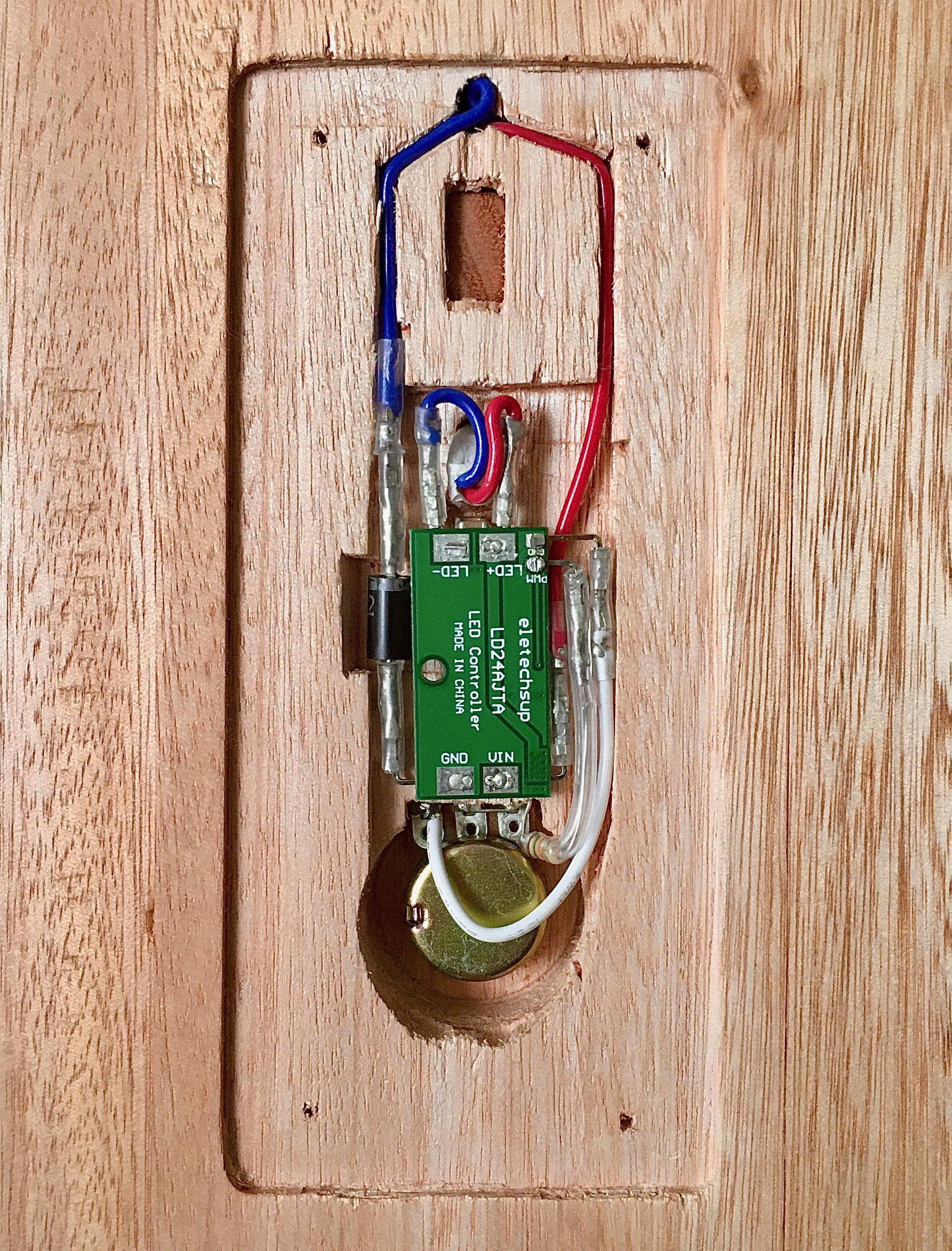
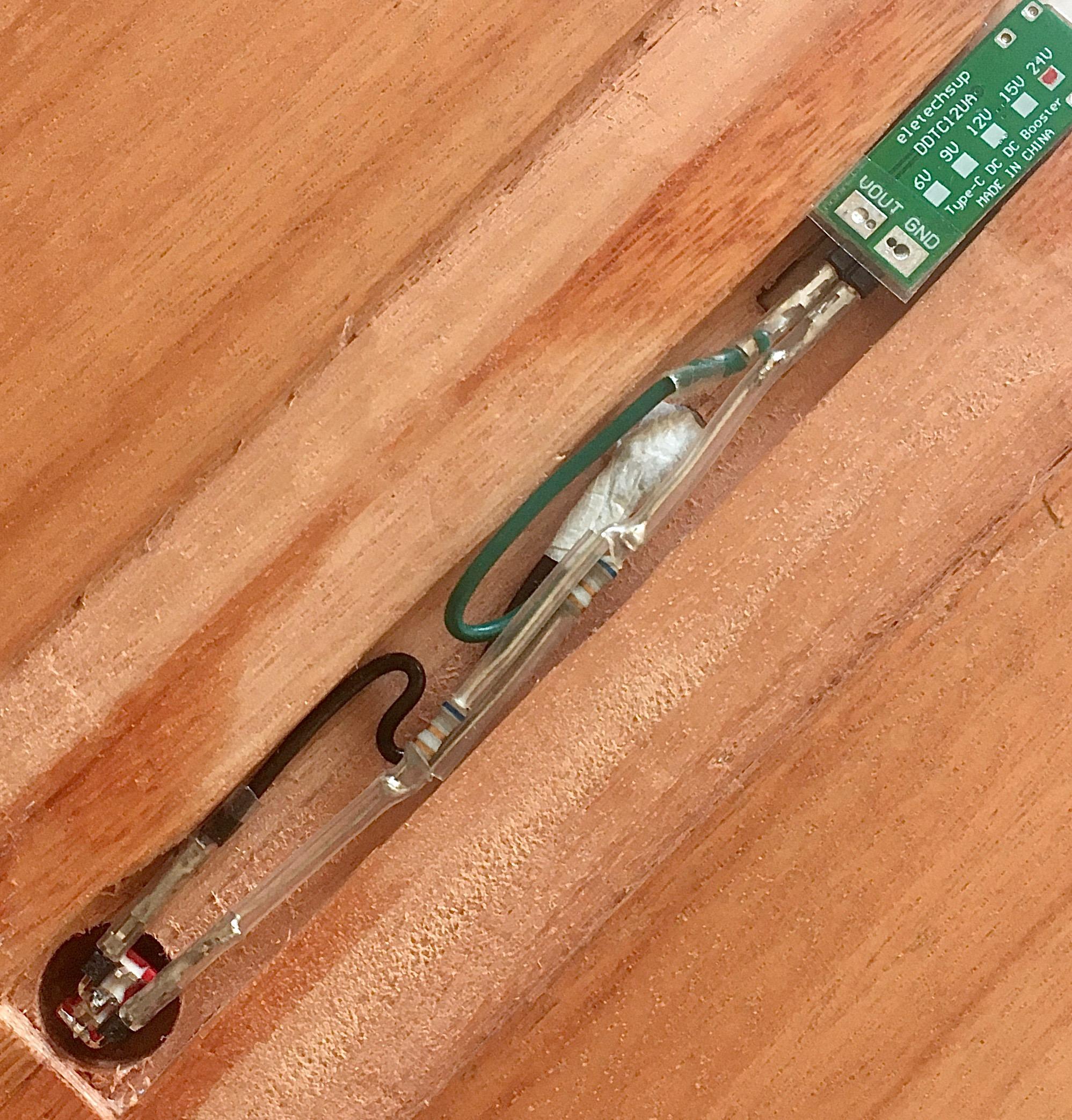
Things got really cramped when fitting the larger board with the extra protections into the space of the previous smaller board 🙈.
#PortuariaLamp
I implemented a protection for the remaining board, with a resistor and a zener diode as explained in a comment here: https://forum.arduino.cc/t/difficulties-with-pt4115-dim-pin/210874
And I also added a Schottky diode to VIN just in case the problem was a polarity reversion between CSN and VIN pins when the lamp is turned off and VIN goes back to 5V while the flicker-filtering capacitor in parallel with the LED is still charged at about 17V 🤔.
Found some unexpected problems with the LED driver in the USB-PD version of the lamp 🤨. It seems the PT4115 chip I'm using is VERY sensitive to ESD on the DIM input, and I already toasted one of the two boards I have.
It would have been nice to know that the PT4115 was such an unreliable chip before ordering the 20 boards with the same chip that are now coming from China 🤦♂️.
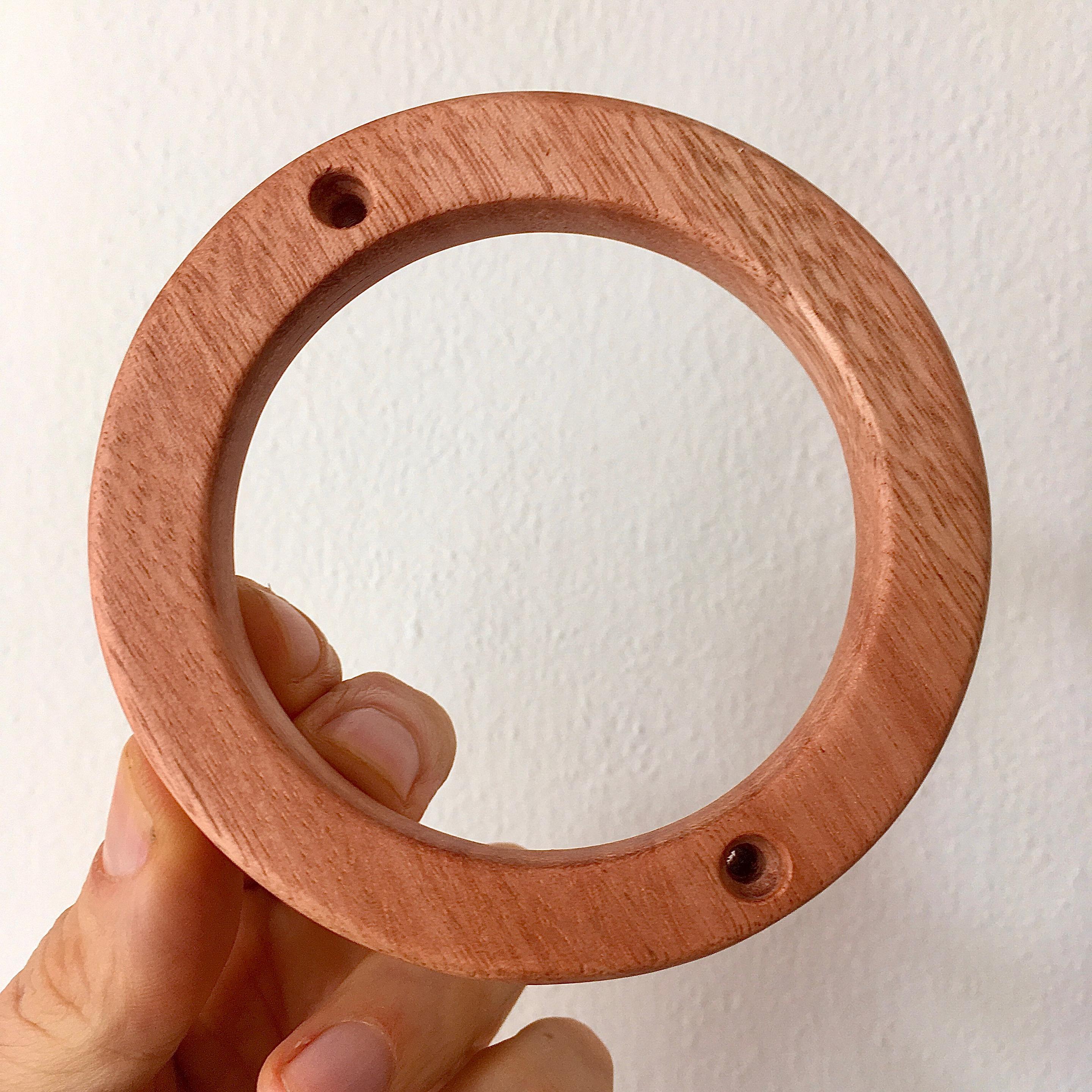
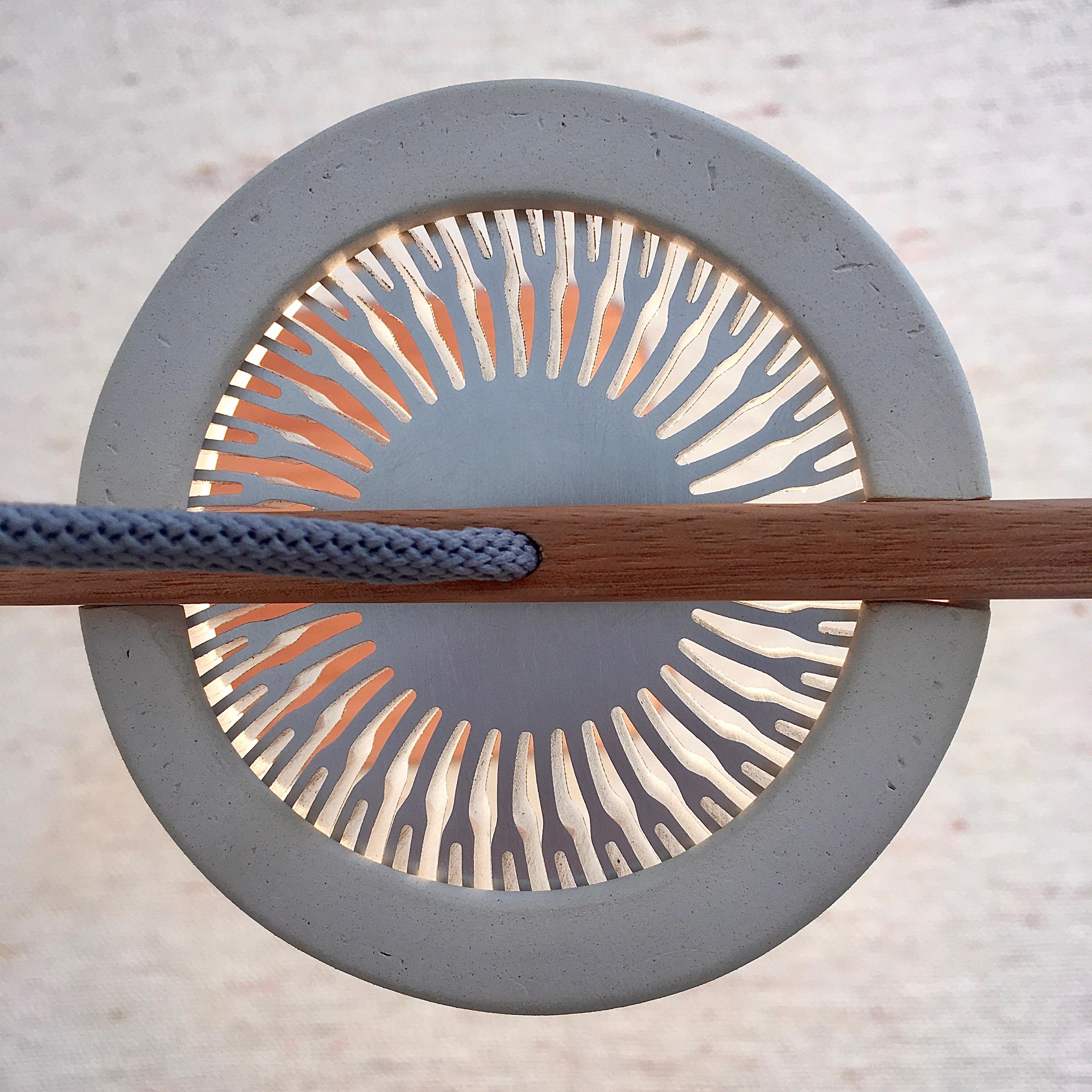
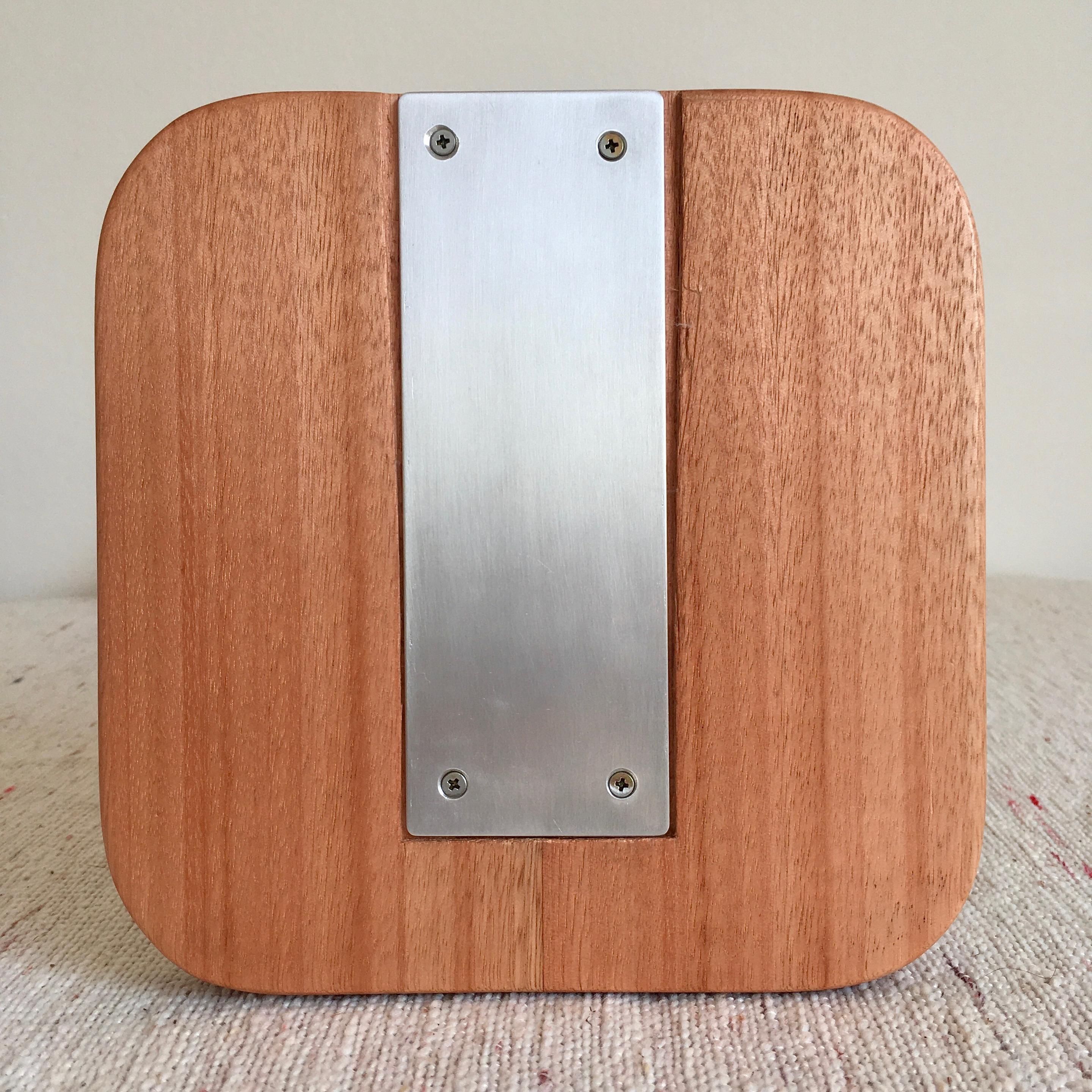
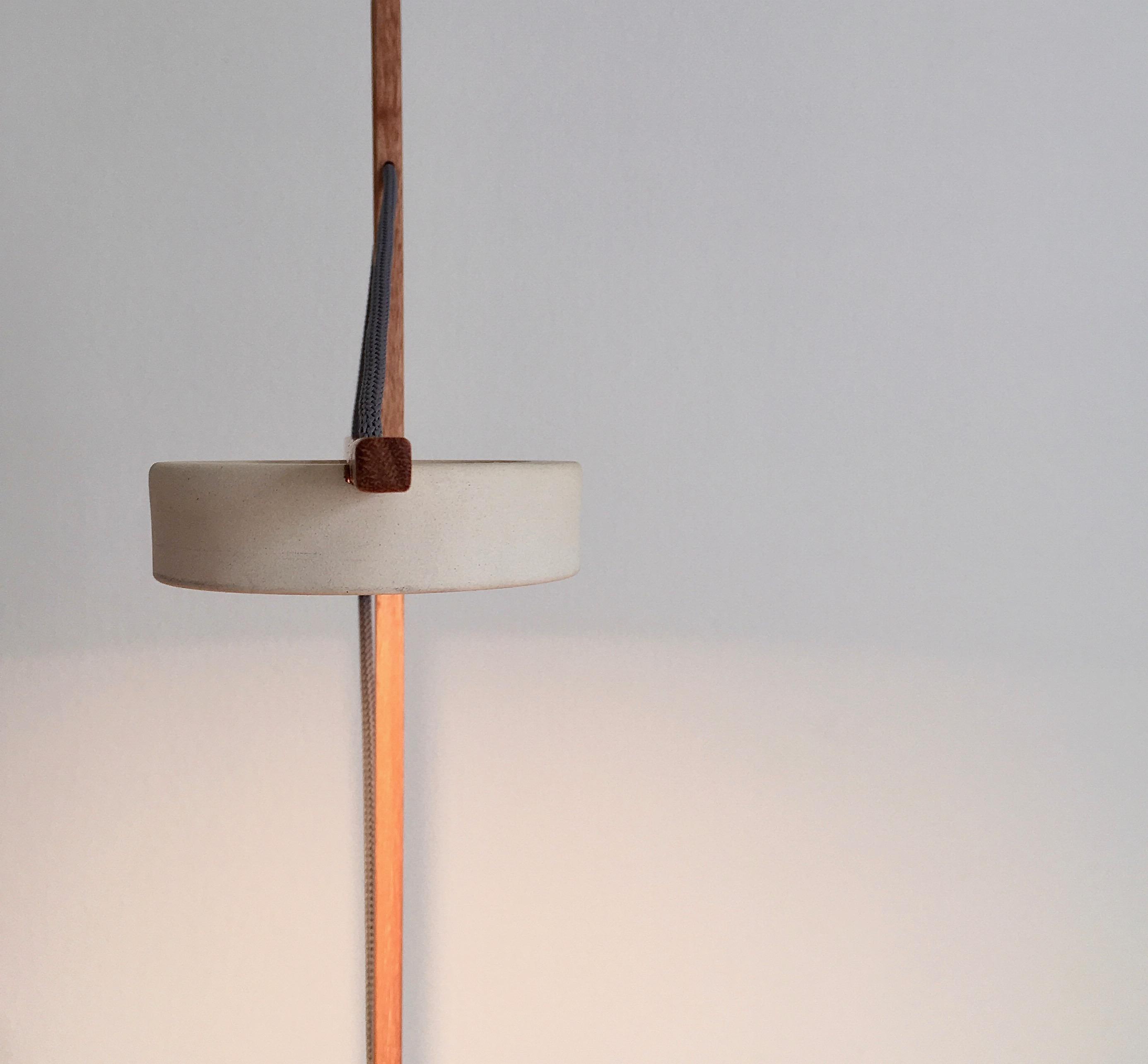
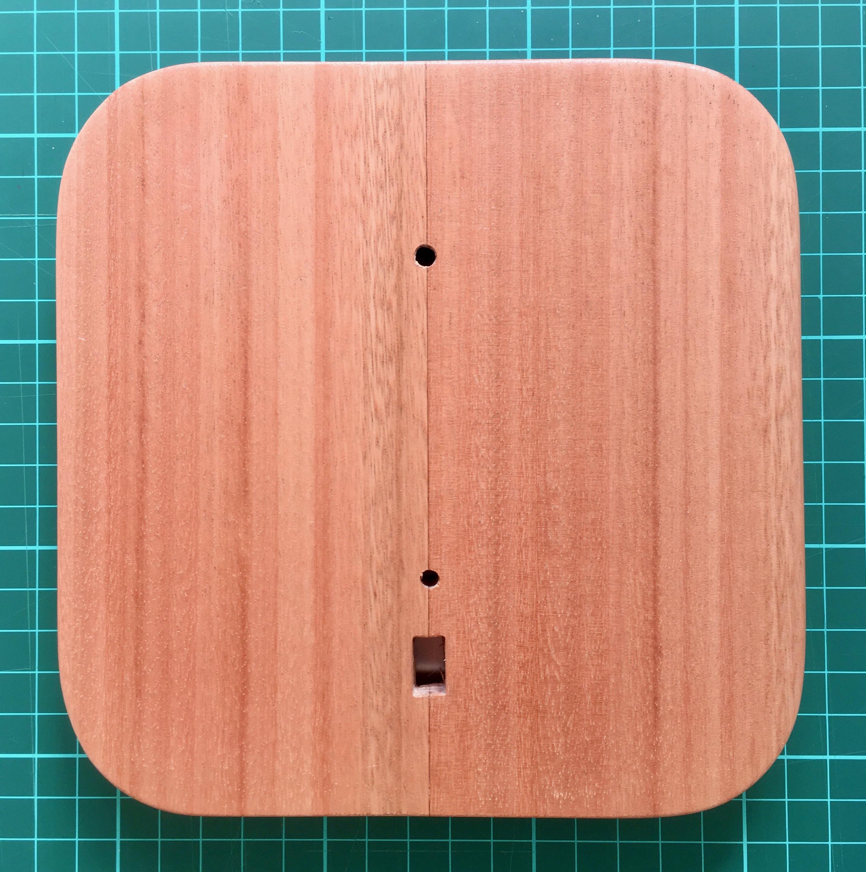
But the problem now is that everything looks very woody and very brown 😁. I liked the contrast of materials that the ceramic made. So, continuing with my materials hysteria, I now started trying to make the same shape of the wooden screen (held with screws from below) but in ceramic, which would need only two holes that are easier to make than the one with cutouts.
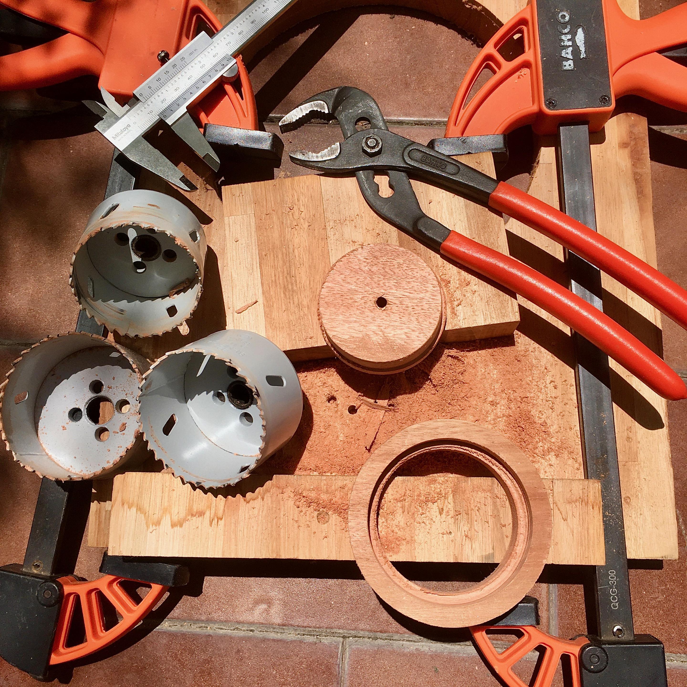
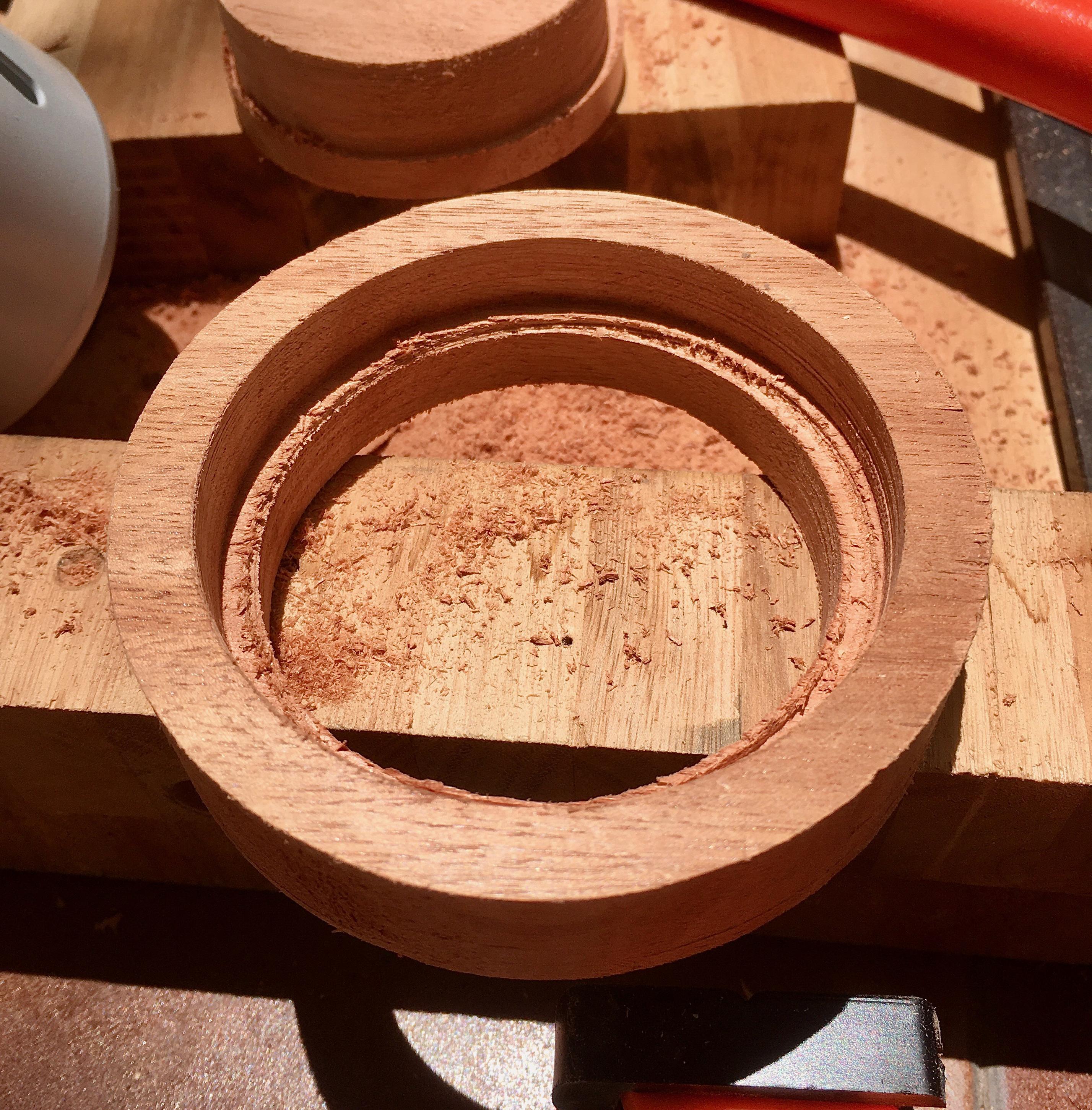
Making the wooden screen is a more precise and predictable process, because it does not shrink between 5% and 9% like ceramic. It takes a lot of sanding work to get an acceptable finish, but eventually the rough cutting part of the piece could be sped up with CNC 🤔.
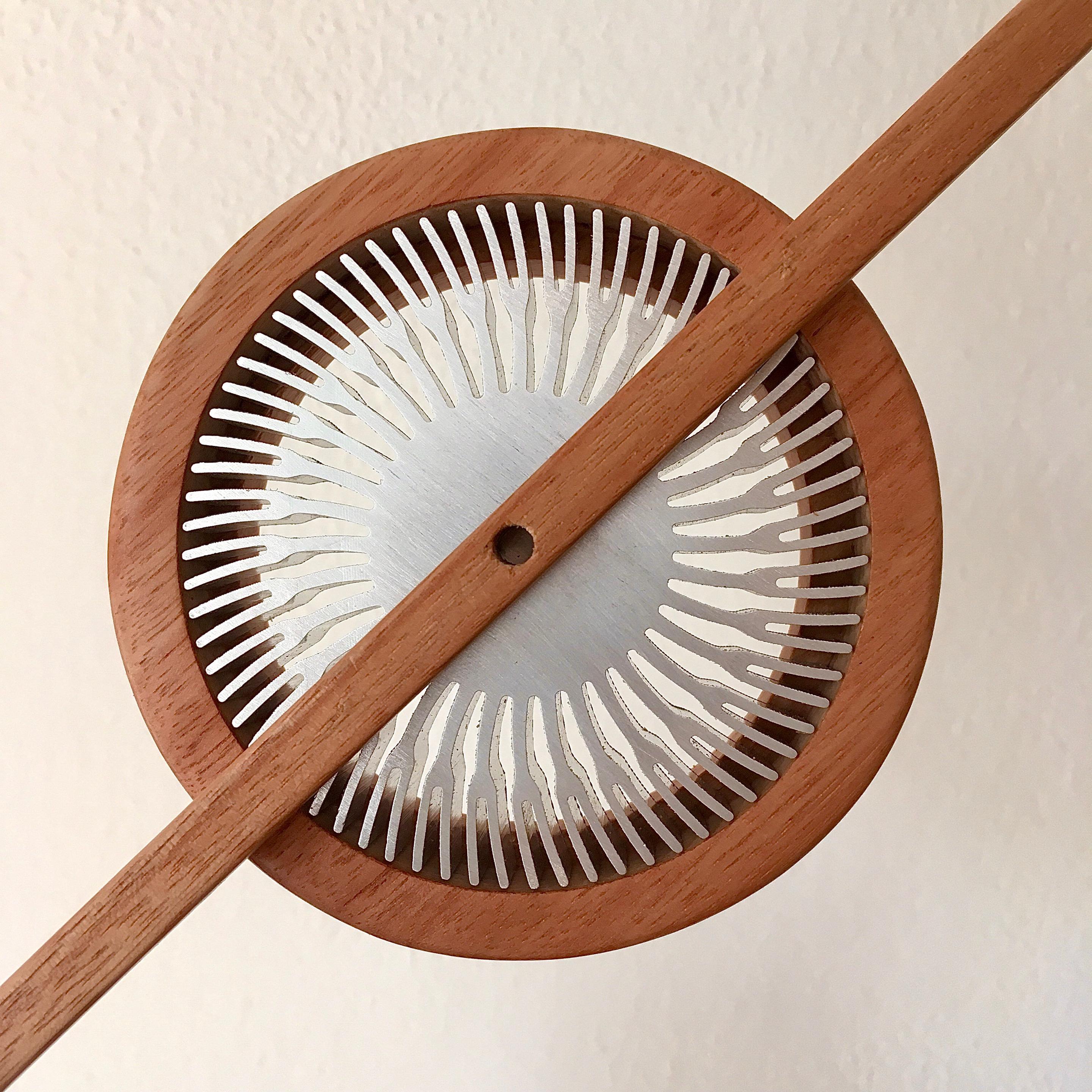
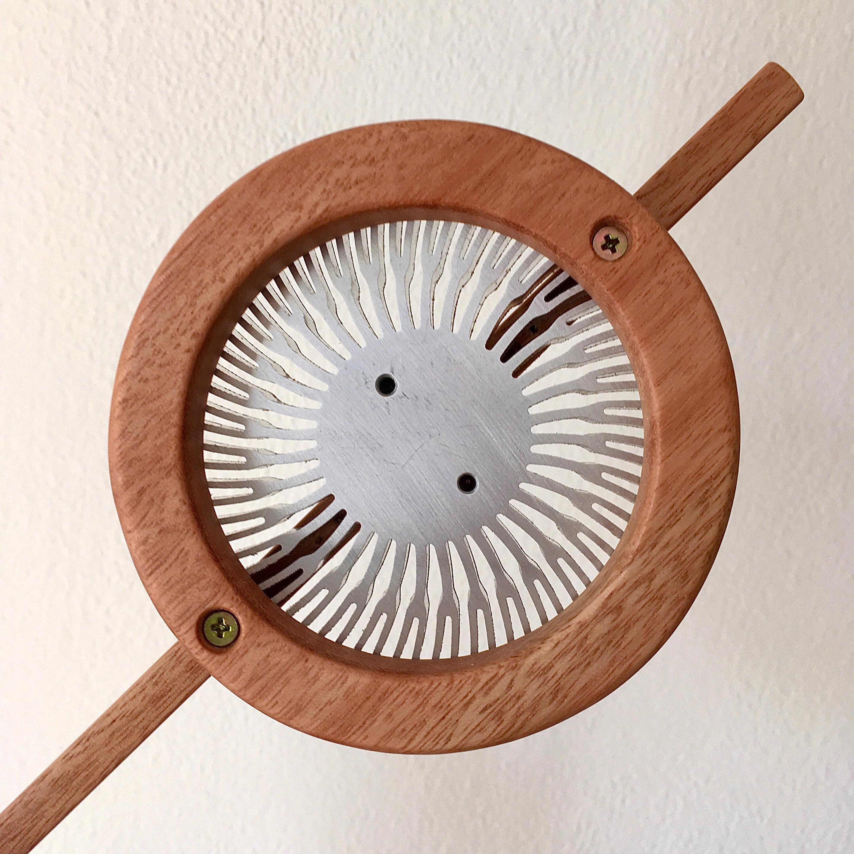
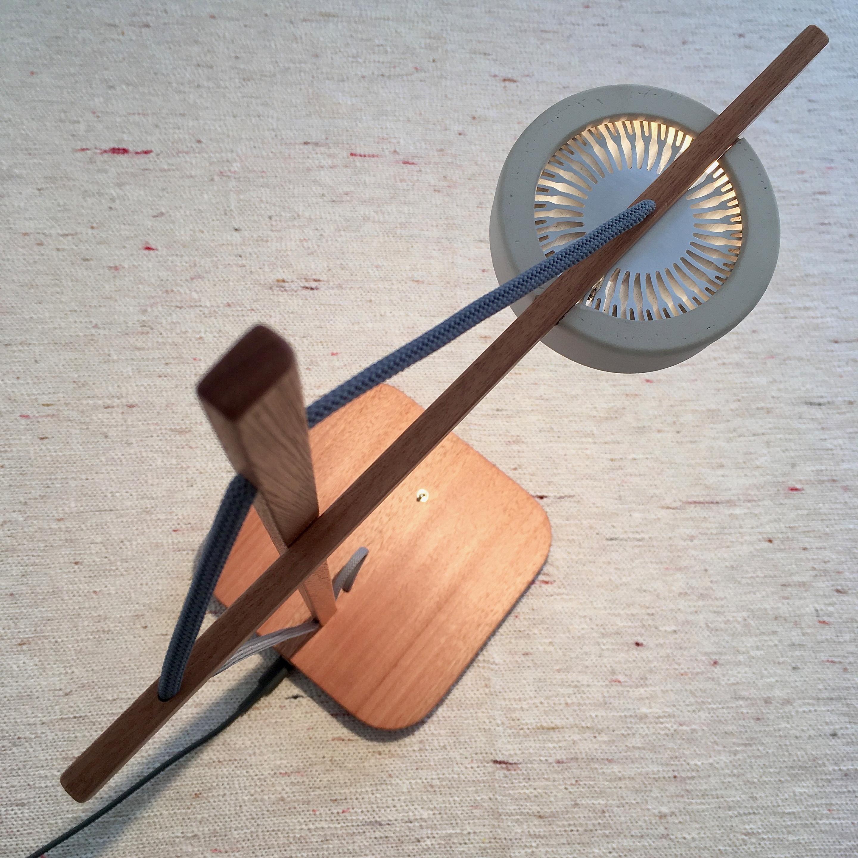
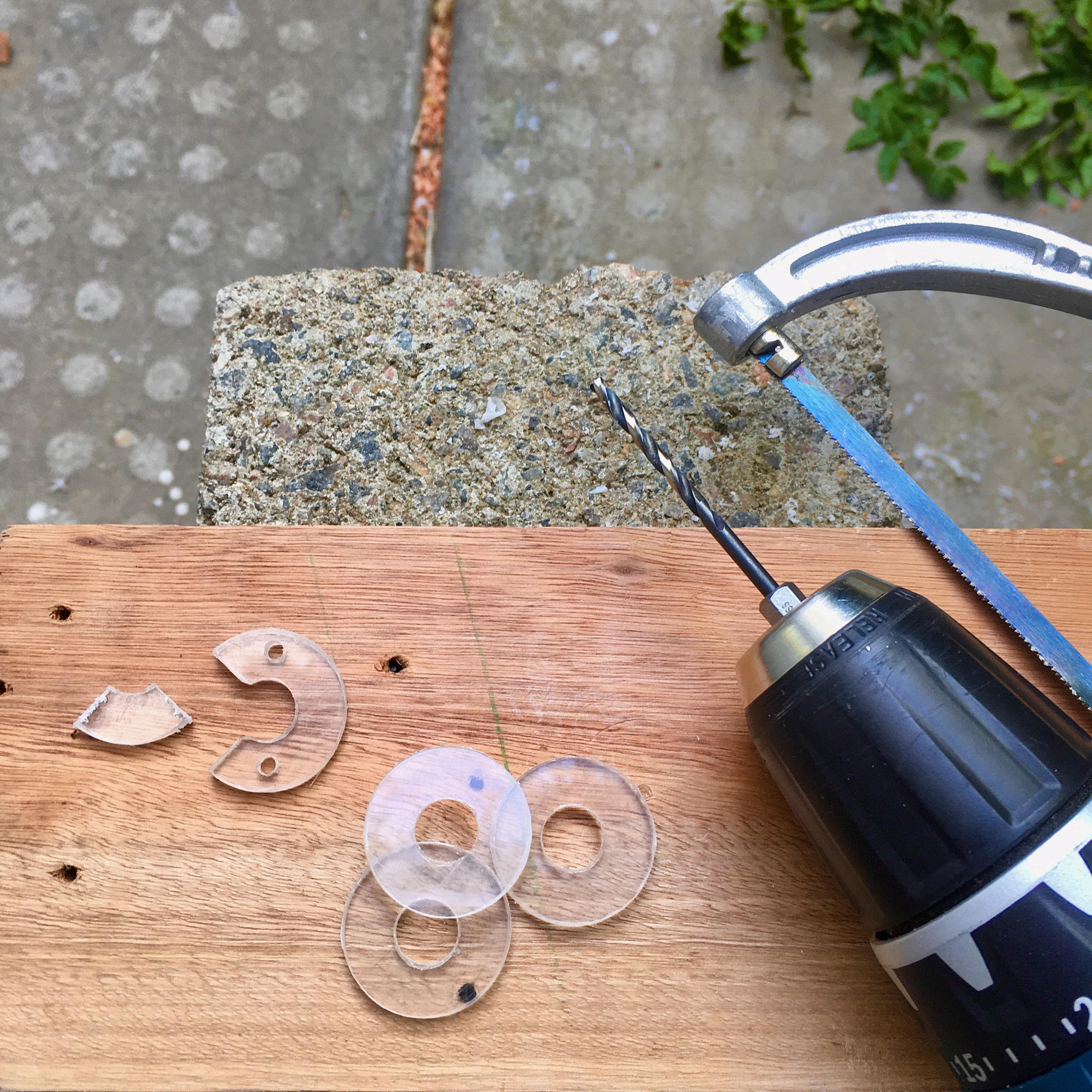
Experiments with an alternative wooden lampshade. The problem with the ceramic screen I was using is that it is very difficult to manufacture, because it deforms when it dries due to the cutouts it has. The only way to avoid that that I found is to make the cutouts after the piece is already baked... and that takes a looooong time with saws and diamond micro-files 🤯.
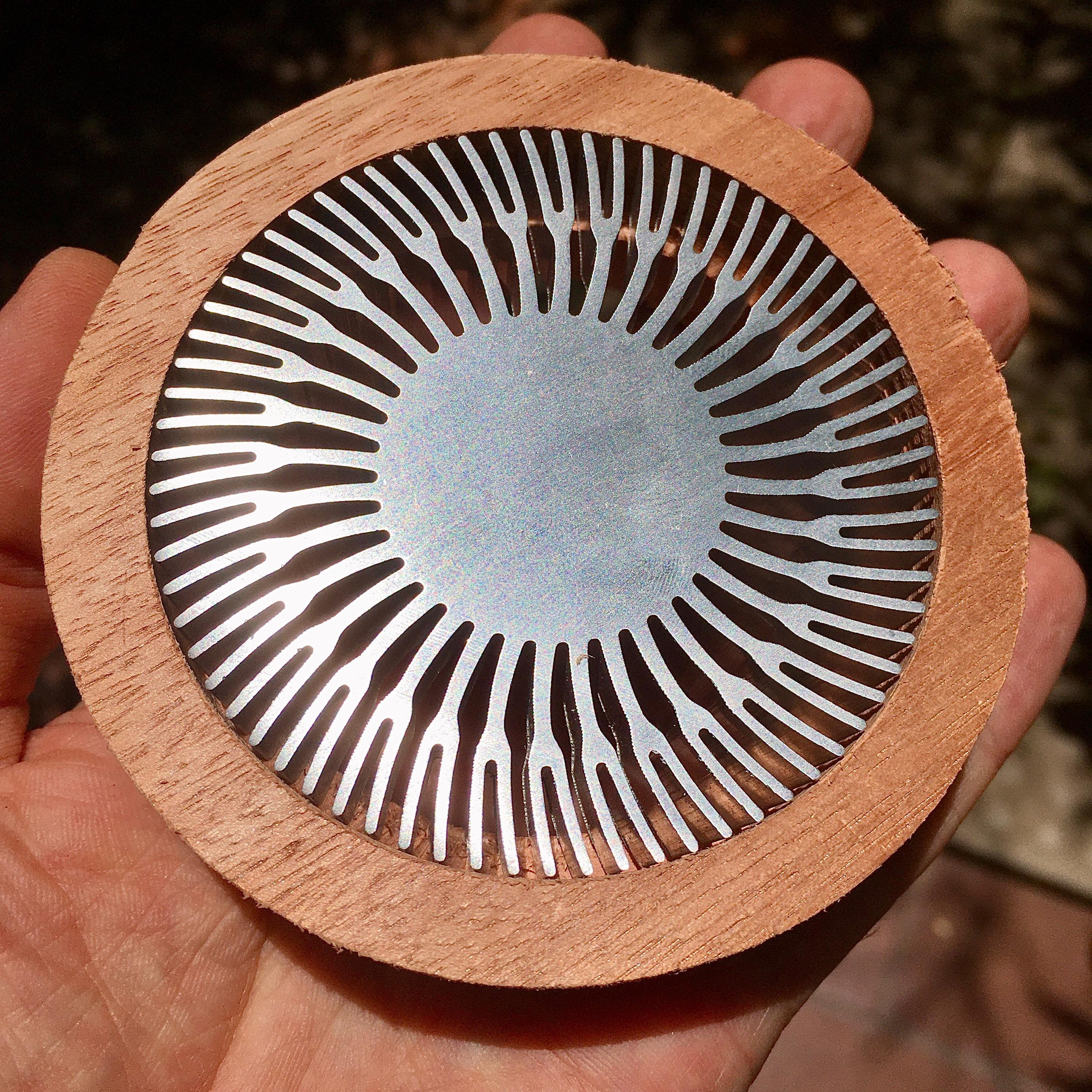
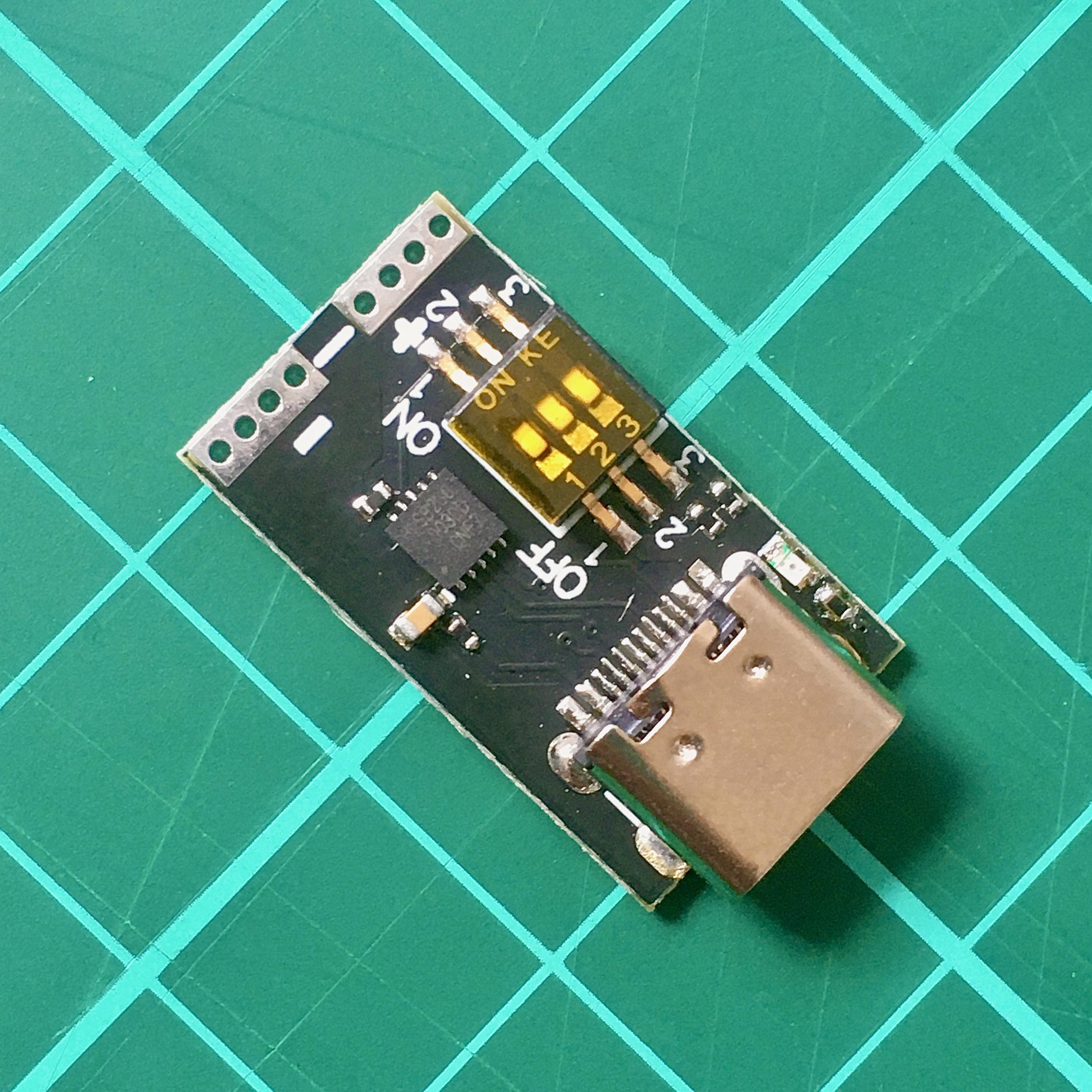
The first attempt with the IP2721 chip didn't work because that chip can't renegotiate another voltage after power on, but I found another chip that can do it: the HUSB238! 🥳
The trick was to put a double switch and another cable to the HUSB238 so that when turning off the lamp it asks the charger to go down to 5V, and the result was quite interesting: 0.19W in standby, 80% less than before 💪.
More efficient USB PD chargers with GaN chips are already on the way...
But not everything is pure pleasure in the world of USB PD. The USB PD charger I'm using is not a big deal, and has a standby power consumption of 0.125W when it's working at 5V (unpresentable for 2024 🙈), but when it's put to work at 20V the standby consumption goes to 1W! 😱. A 5W lamp that consumes 1W when turned off?!?! 💩
After a couple of days pondering this depressing result, I thought of trying something: Make the charger go back to 5V when the lamp is off!
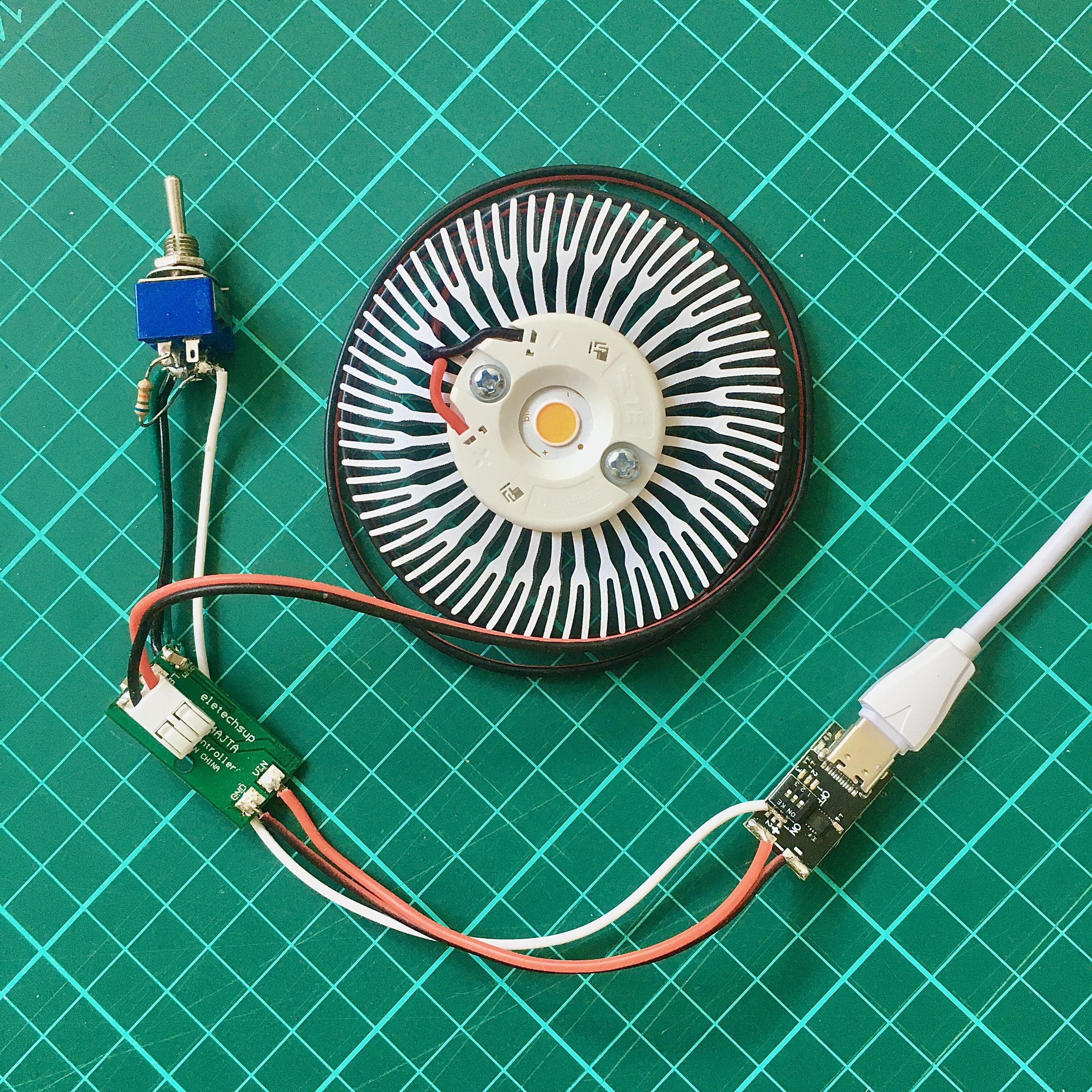
The solution? Use the new USB PD chargers, which can deliver different voltages if we ask them nicely 😁. I'm using a board with the HUSB238 to ask the charger to give me 20V, which is enough to turn on the 17V LED and makes everything work more efficient and cooler because the current in the cable is only 0.25A, converting from 220V to 20V is more efficient, and the step-down to regulate the LED current is more efficient than the step-up of the previous version.
The problem with the previous circuit, which worked with the 5V of the common USB, is that it had a lot of power losses due to the inefficiency of working at such a low voltage. The charger got very hot due to the low conversion efficiency from 220V to 5V, power was lost in the cable due to the 1.4A current, and the step-up worked hard if the voltage dropped much below 5V due to using a charger or cable of dubious quality 👀.
New electronics design that improves energy efficiency from 63% in the previous USB version to 79% with a new circuit that uses USB PD at 20V 😎.
🧵 #PortuariaLamp #lamp #prototype #LED #driver #USB #PD #electronics #efficiency
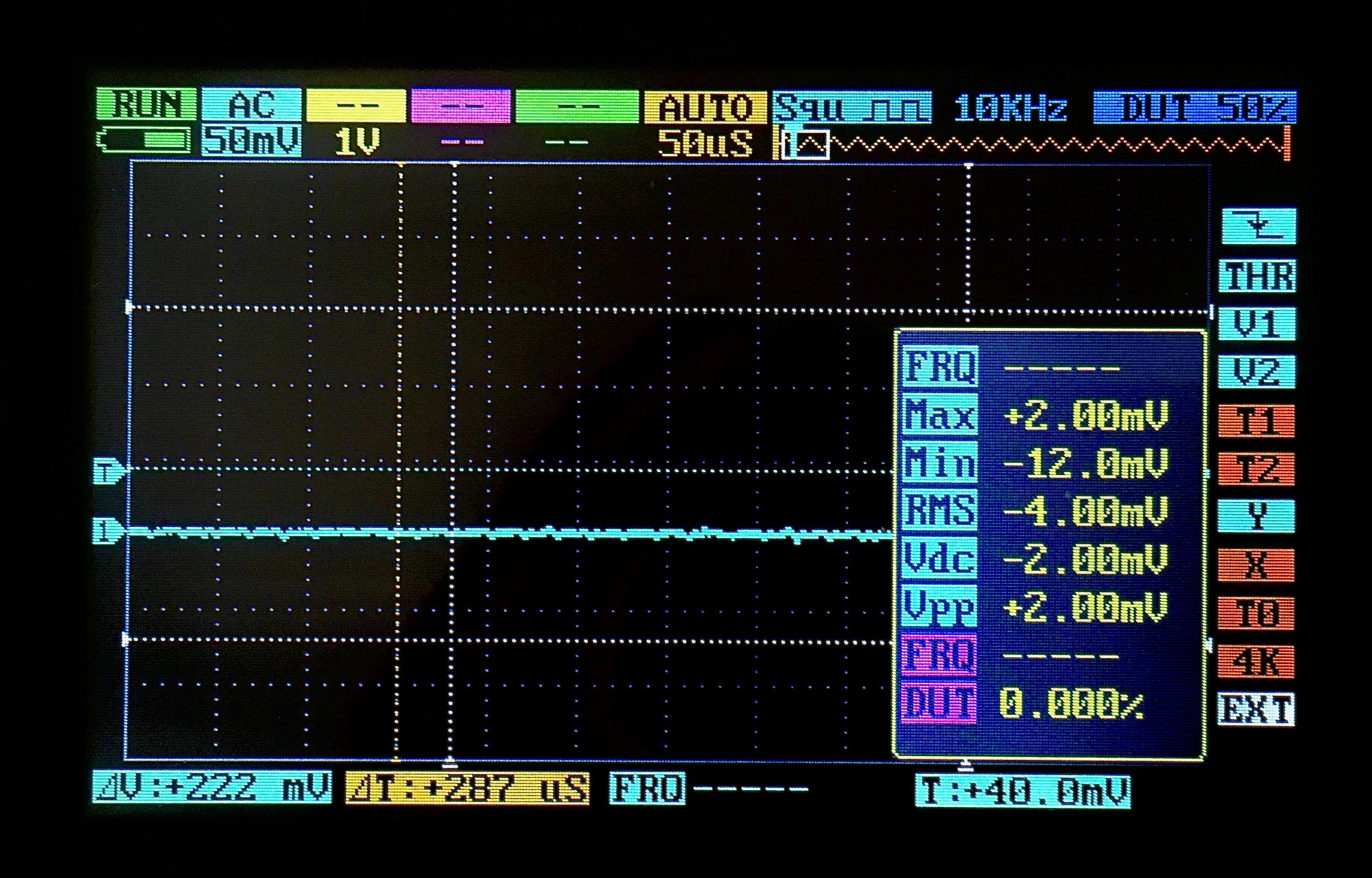
I also managed to stabilize the driver circuit to reduce the oscillations of the light intensity to less than 0.2% (2 mV, 0.84 lumens), from 72% that the original circuit had 😱. The trick was to add four 22 uF ceramic capacitors in parallel to the LED, and another 10 uF at the potentiometer input.
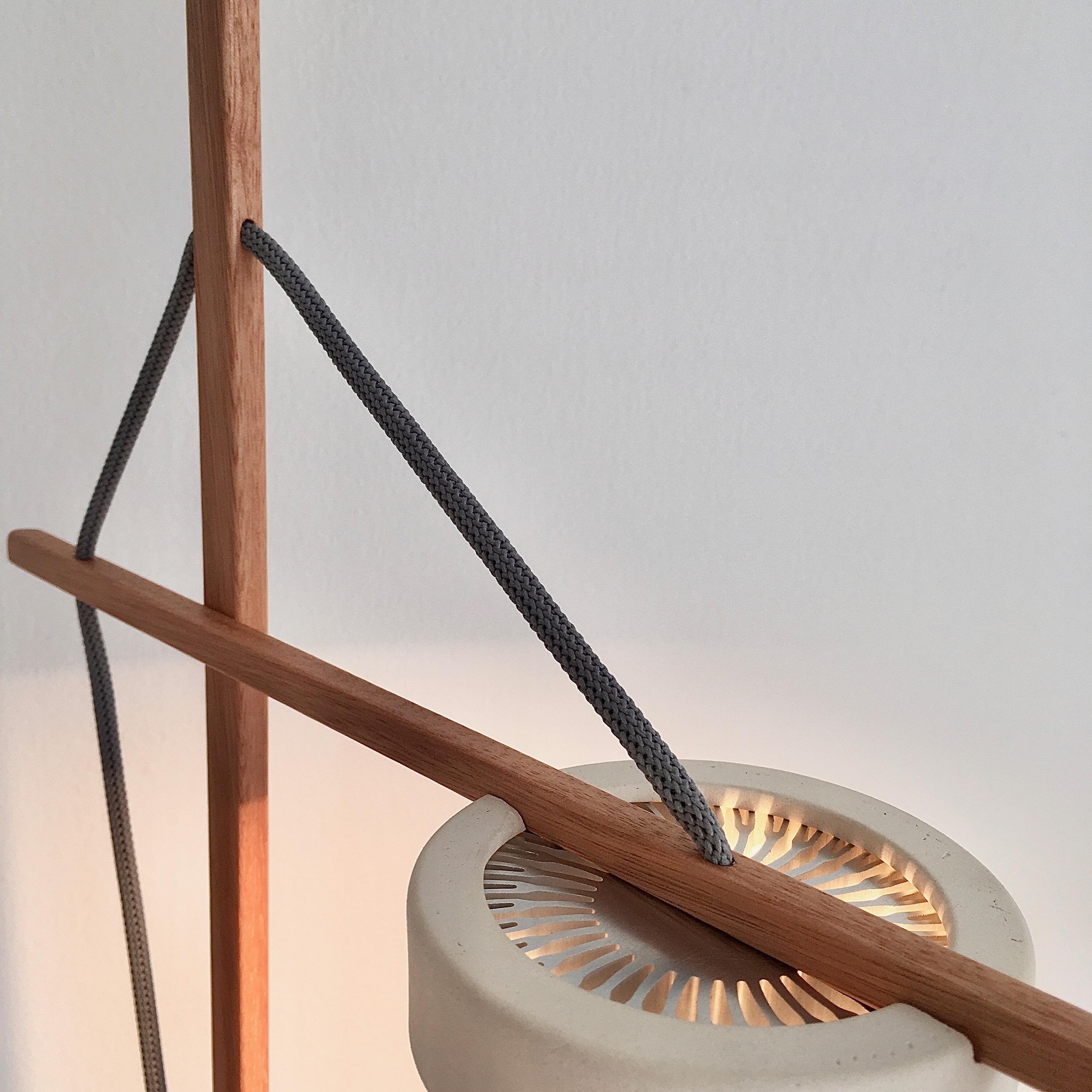
The goal remains to simulate natural lighting as best as possible, and after all, the sun does not flicker 🤔.
🧵 #PortuariaLamp #lamp #prototype #LED #driver #dimmer #flicker #electronics
The design of the dimmable version of the Portuaria is progressing, slowly but it is progressing 🥳.
Organizing the wiring of the components inside the base was quite a challenge because there are things with fixed positions (potentiometer, LED cable, vertical rod and power plug) and the circuits have to fit into the gaps between those things 🤯. I think it could be simplified more, but for now everything fits into its place.
🧵 #PortuariaLamp #lamp #prototype #LED #driver #dimmer #electronics
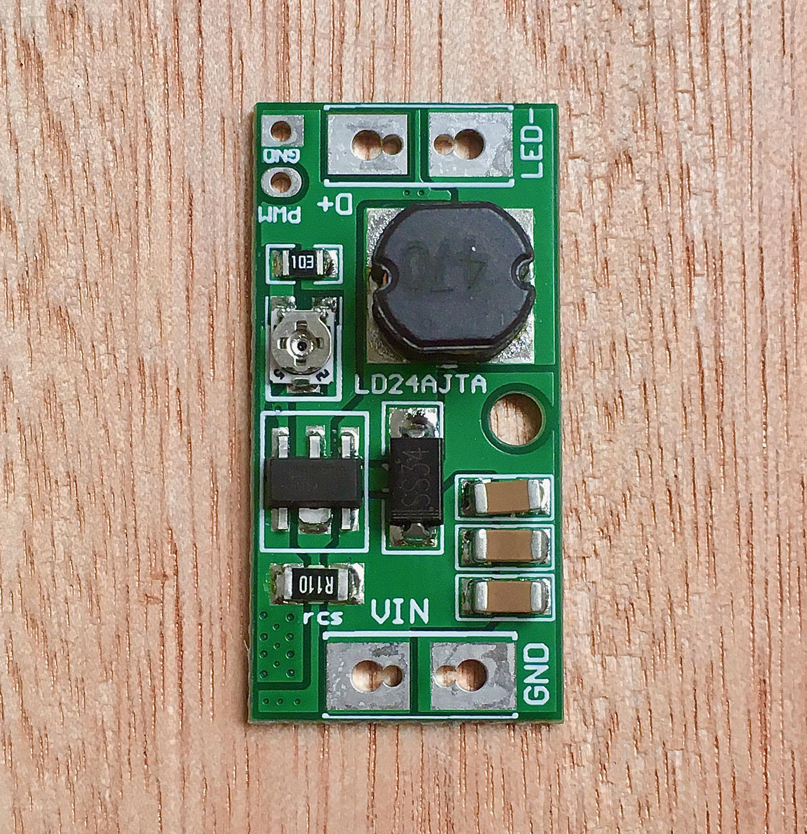
But don't panic! 😁 I have a plan: Use a step-down LED driver like the one in the photo, with a switching transformer from 18 to 30 volts... or 20 volts from an USB-PD 😎.
The first tests gave a total efficiency of 87%, an amazing improvement 🤩. There are still some issues with the flickering produced by the LED driver (a whole topic, it's for another post), but they are being resolved 💪.
🧵 #PortuariaLamp #LED #driver #efficiency #flicker #electronics #USB
- USB chargers. Usually you can only use up to half of the maximum current without the output voltage dropping too much.
- The voltage regulator I'm using loses efficiency if the voltage drops below 5 volts, and it gets too hot 🥵.
- The total efficiency is terrible, it only reaches 63% due to all the power losses from the previous points 😱. The Huanacus I built before with a simpler circuit that was only an 18 volt transformer, an LED and resistors reached 80% efficiency 😐.
Recalculating! I've been doing measurements of various parameters on the last prototype, and I'm less and less convinced that it's a good idea to run a 5 watt lamp from a 5 volt USB 🤨.
Here's the list of problematic issues:
- Crappy USB cables 👀. Unless they're of very good quality, they use very thin conductors and connectors with dubious plating. This produces a significant voltage loss of up to 0.4 volts with the currents that the circuit handles.
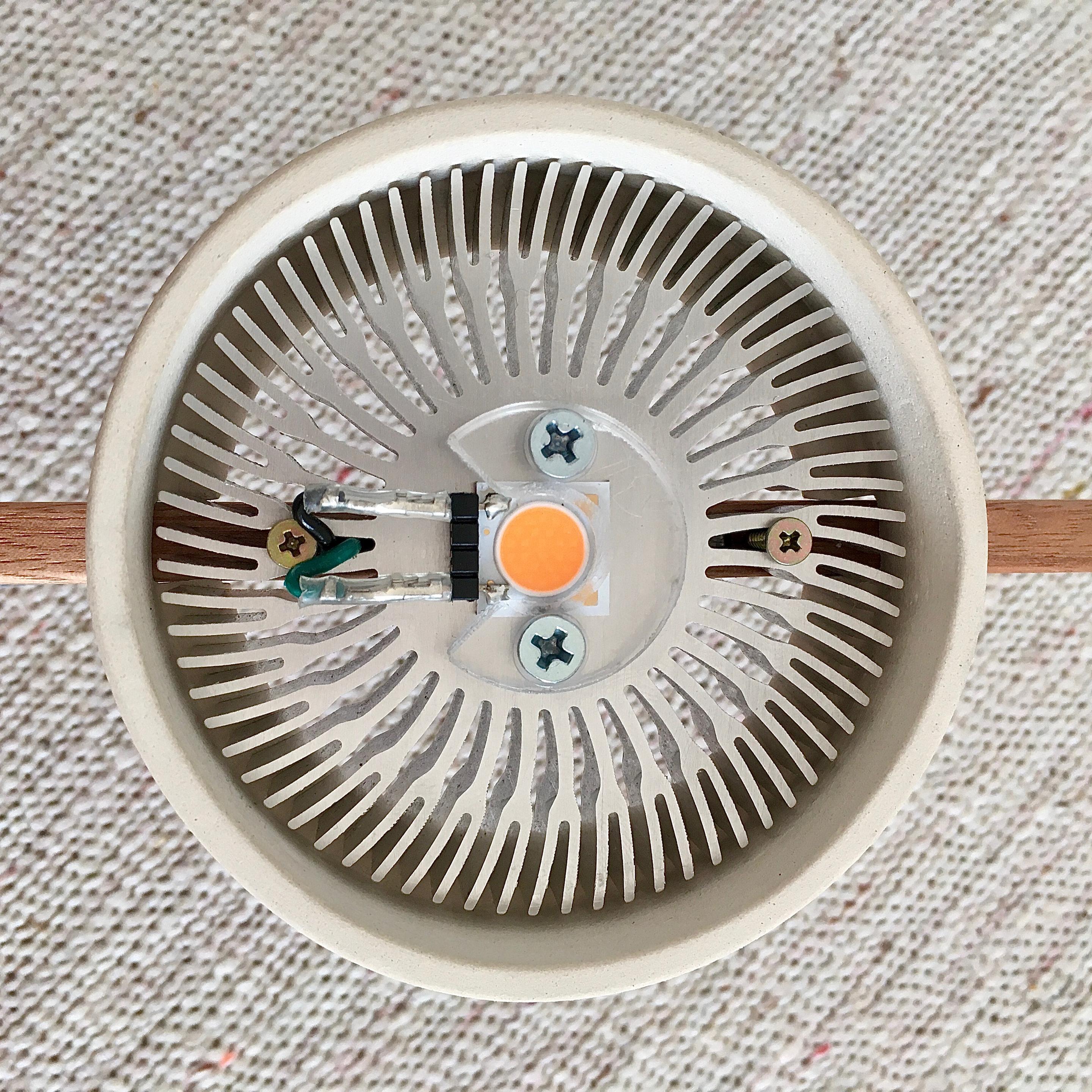
- Aluminum heatsink for the voltage regulator. This worked quite well, the temperature of the circuits dropped 10 C compared to the previous version.
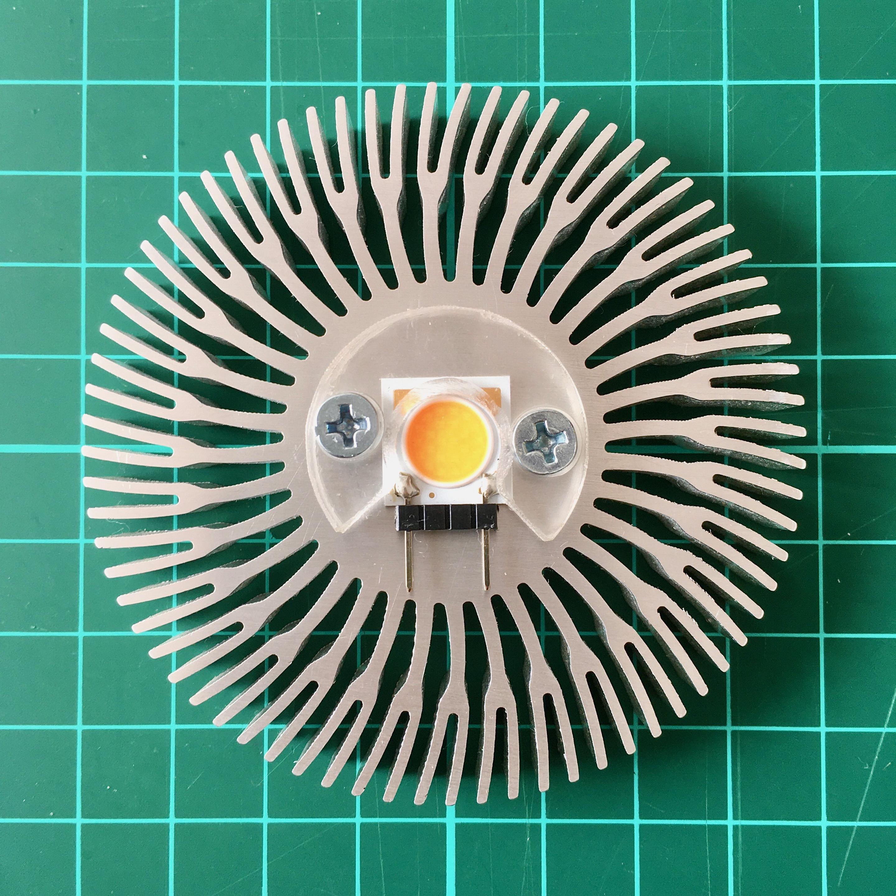
- New LED holder with connector. This allows changing the LED without needing a soldering iron, increasing repairability 💪. Made of polycarbonate for now, but perhaps ceramic in future versions to reduce plastic parts to the minimum necessary.
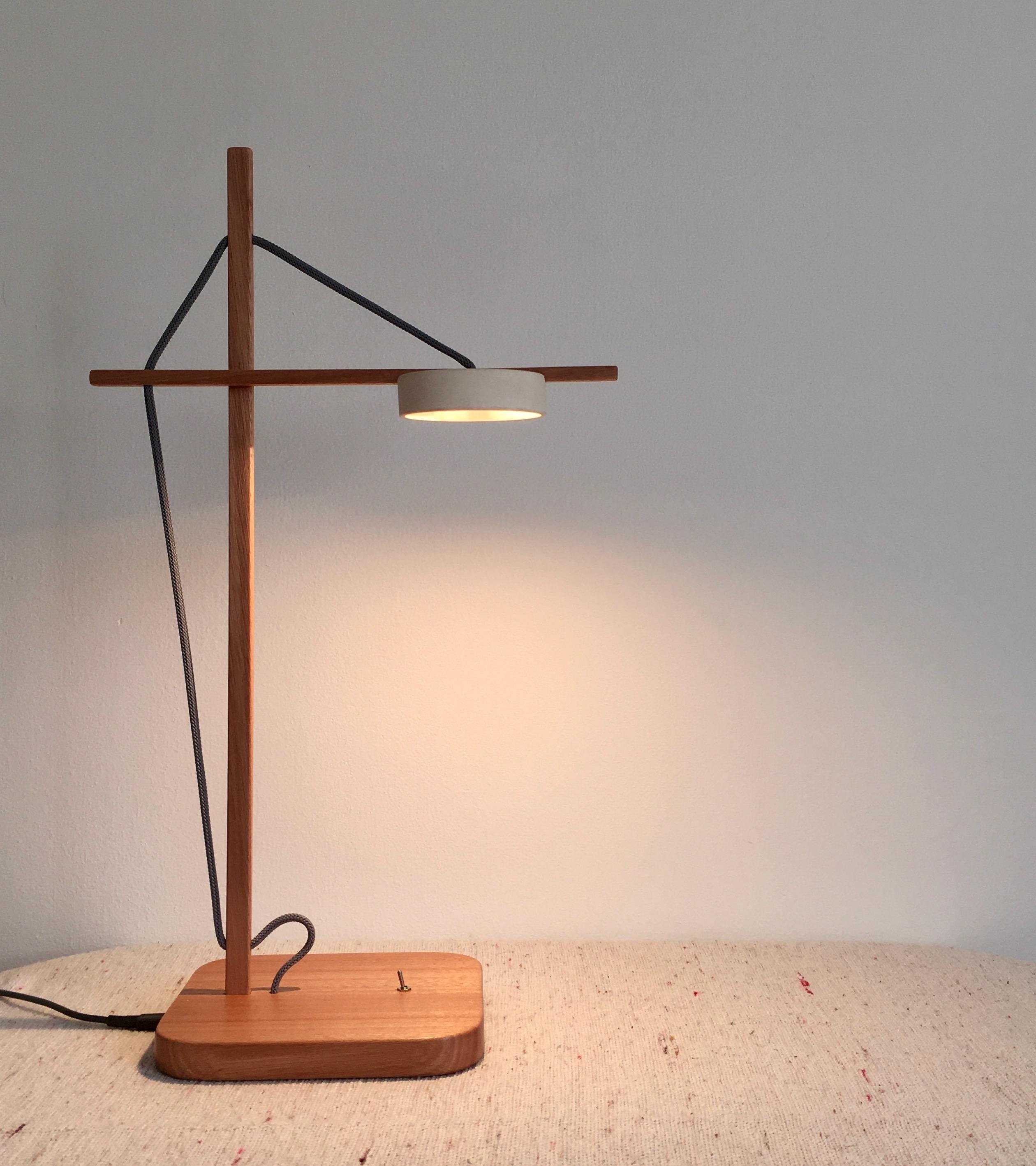
Portuaria 0.3!
- More angles! Square and rectangular rods add contrast; it's easier to align the holes and slots when making them; and they use the same eucalyptus wood as the base instead of Palo Blanco.
- Larger base surface. The idea was to give the base more visual weight in relation to the ceramic screen, turning the circle into a rounded square without modifying the width and length. But I think I went overboard and now it's too big 😂.
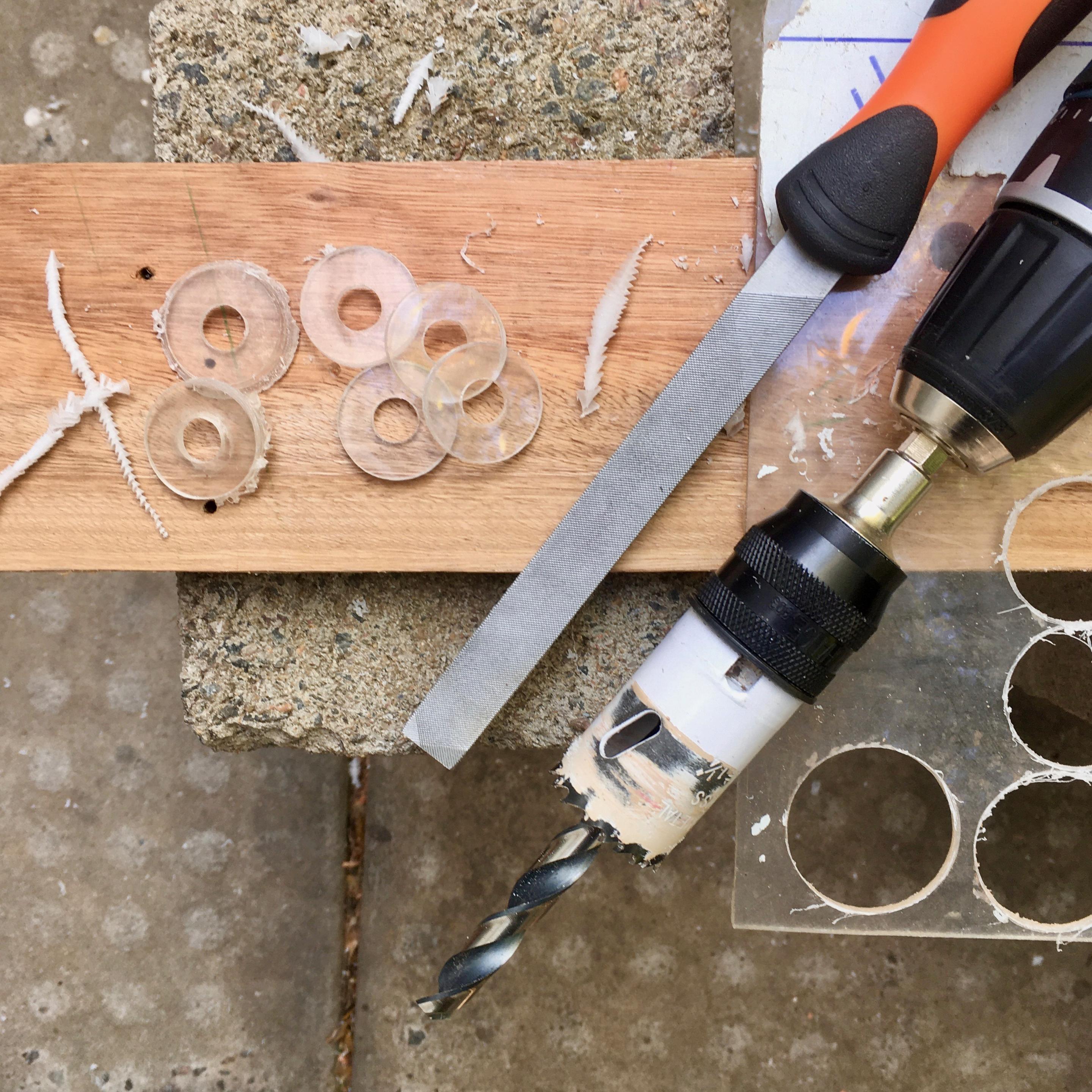
New LED holder design, now with connector so you can change the LED without having to use a soldering iron 😎.
I did it to be able to mount the Bridgelux V8s I'm using, with 3mm polycarbonate scraps I had around here.
The future plan is to migrate to the Bridgelux V6s, which have more standard measurements and can be used with TE's Z35 holders.
🧵 #PortuariaLamp #lamp #prototype #LED #holder #lighting #DIY
Another change is that instead of the printed circuit board it has an aluminum plate to better dissipate the heat from the regulator. The goal is to create a product that lasts several decades in regular use, and the rule of thumb is that for every additional 10 C the useful life is reduced by half.
It's probably not the final shape of the base, I'm already thinking of a third prototype that needs less sanding! 🤧.
Client Info
Server: https://mastodon.social
Version: 2025.04
Repository: https://github.com/cyevgeniy/lmst