Multi-Mode MIDI Step Sequencer – CDR Format – Part 3
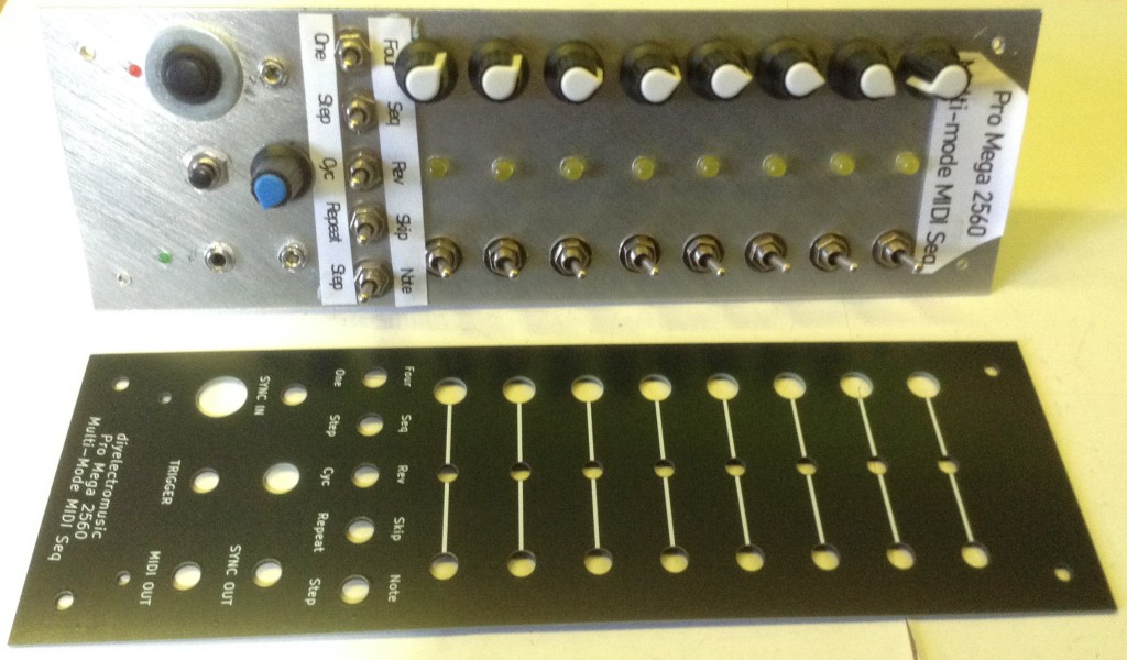
This post revisits the “CDR format” (CD Rack Format) panel version of my Multi-Mode MIDI Step Sequencer.
- Part 1 detailed the build and testing of the panel.
- Part 2 updated and enhanced the Multi-Mode MIDI Step Sequencer code to run on the panel.
- Part 3 (this post) details the design of a panel using a PCB manufacturer.
Warning! I strongly recommend using old or second hand equipment for your experiments. I am not responsible for any damage to expensive instruments!
If you are new to Arduino, see the Getting Started pages.
Parts list
- PCB-based new front panel (see below).
- The parts from the Multi-Mode MIDI Step Sequencer – CDR Format module.
Panel Design
A key issue was that I hadn’t really documented the dimensions I’d used in the design of the original panel, but after finding the old cardboard cutout and comparing to my built panel I was able to reproduce the dimensions.
It also turns out that I haven’t really listed the hole sizes I’ve been using for panels either, so that was part of the first task too.
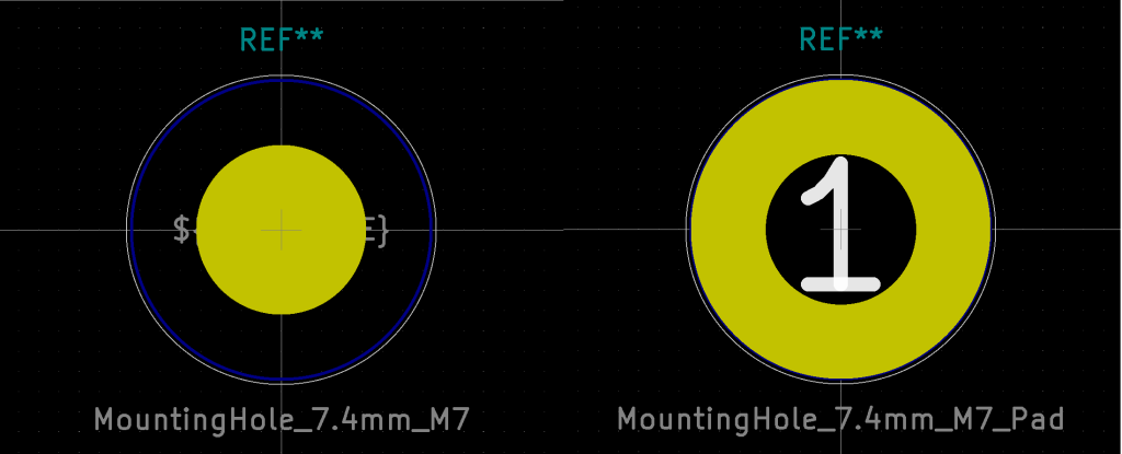
I had to create a custom KiCad part for an M7 hole. I based this on the existing M8 holes (one with a pad and one without).
The rest of the holes used, that match the connectors I’m using, are as follows:
PotentiometerM7 (7.4mm) mounting holeAudio OutM8 (8.4mm) mounting holeMIDI TRSM6 (6.4mm) mounting holeToggle SwitchM7 (7.4mm) mounting hole“Thonkiconn” Jack SocketM6 (6.4mm) mounting hole3mm LED3mm mounting hole5mm LED5mm mounting holePower Switch12.5mm diameter edge cut cutoutThe key dimensions are indicated below. The whole panel is 250×80 mm with mounting holes 10x10mm from each corner and 20mm clearance top and bottom for mounting.
As I’m using a PCB design tool for the panel, I’ve included a rear GND zone, so left a small pad exposed near the bottom to solder to if required. I did think about using “pads” rather than plain holes to allow switches and potentiometers and so on to connect to the GND zone, but in the end opted for plain holes.
Note: there is one error on the final PCB – the toggle switch was designed with a M6 hole and actually I need an M7, so I had to widen it slightly.
There were a couple of complications with switching over, that I wouldn’t have had with a new build:
- The power switch needed desoldering and resoldering as the nut is on the inside. Unfortunately I managed to damage the click mechanism and on first try, it was quite unreliable latching in the on position. I had to replace it completely.
- Two of the three-way switches had their nut/shaft fail on me – I managed to do up the nut most of the way, but not completely and then the threaded shaft started rotating meaning I could neither do it up or undo it. They work, they are fixed in, but they are a little wobbly which is really annoying! But I’d need to desolder a fair bit to replace them. They’ll do for now. Sigh.
Some enhancements were possible too whilst updating the board:
- I’ve added a 10nF capacitor across the terminals of the toggle switch to aid debouncing.
Other enhancements I’m considering that I might add at a later date:
- Add capacitors across all pots for smoothing.
- Add clamp Schottky diodes to the sync IN/OUT sockets, so they aren’t just a direct connection to the microcontroller’s GPIO ports. This was always something I meant to do anyway.
In fact, I might even add a proper buffer stage for the sync jacks anyway – a transistor input stage and protected output stage, as used in my Arduino Drum Trigger to MIDI Shield PCB and my Arduino Clock Generator Shield PCB. Or even include a buffer in the shape of a 74HC14 or similar.
Closing Thoughts
I thought this would be a straight swap and relatively straight forward to do. Unfortunately the use of cheap components caught up with me on this one.
Still, I think the result looks pretty good and it does all now work fine.
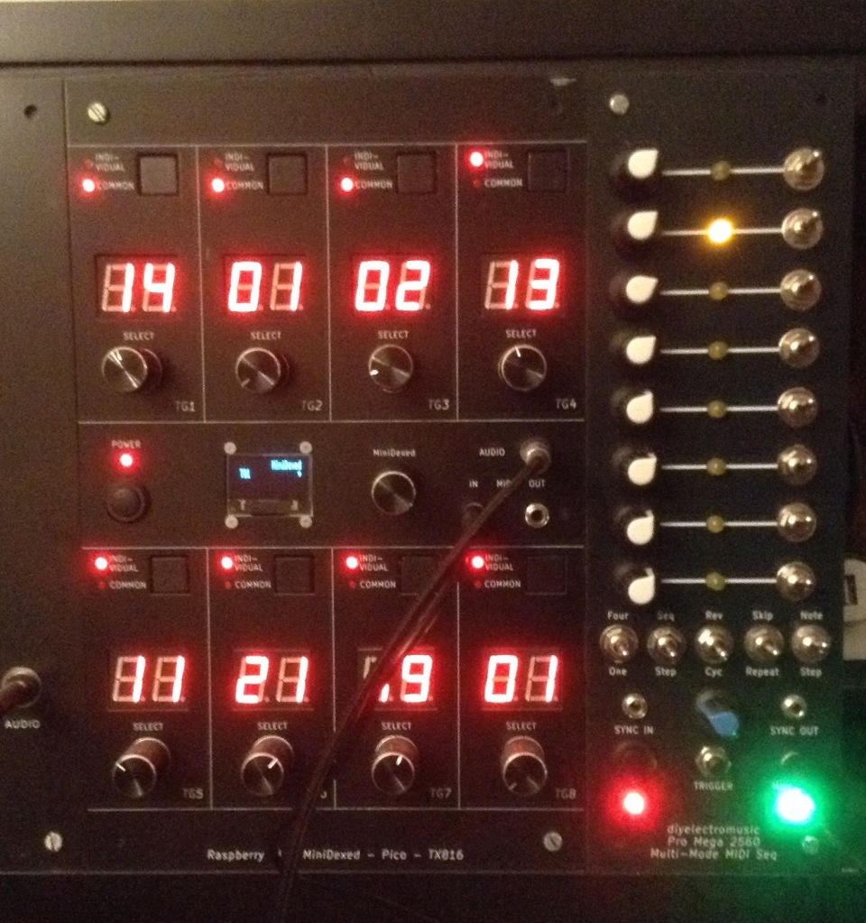
It certainly looks great next to my MiniDexed TX816.
Kevin
#ATmega2560 #cdrFormat #digitalPins #led #midi #pcb #potentiometer #ProMega2560 #sequencer #stepSequence