
What to do when a #volume #potentiometer on a #vintage #headphone #amplifier starts to make "scratch" noises when operated?
#potentiometer

Oh look ! My #achievmentunlocked so far today : #Potentiometer based controllers on #Amiga, like atari 8bits and c64 #paddles and 90s area PC flight simulator sticks, will be managed on the next version of #MameMinimix .I didnt even know it was possible on amiga. The code to do this is actually quite complex (watch github if interested) and needed a bit hack to work alongside the lowlevel Api. One other Milestone act is that... hey ! finnaly we can have driving game with actual analog wheel and brakes on Amiga !!! #retrogeek

🌘 學習基礎電子學:打造個人專屬的螢火蟲
➤ 從零開始,用動手實踐點亮學習之夜
✤ http://a64.in/posts/learning-basic-electronics-by-building-fireflies/
作者分享了透過親手製作電子「螢火蟲」,從零開始學習基礎電子學的歷程。他利用 Astable Multivibrator 迴路,結合光敏電阻(LDR)和電位器(Potentiometer),成功調整了 LED 的閃爍時間和亮度,使其能在夜間發光,並優化了能源效率。過程中,他克服了元件故障、模擬器不符預期、焊接煙霧問題,甚至從廢棄電路板上拆卸元件,最終成功製作出多個功能性的「螢火蟲」,重拾了學習新知的熱情與樂趣。
+ 這篇文章太激勵人了!從完全不懂到自己做出會亮的「螢火蟲」,過程中的各種小挫折和解決辦法都寫得非常真實。我也想試試看!
+ 作者分享的學習方法很棒,結合 AI 工具和實際操作,讓電子學不再是枯燥的理論。特別是那個自製的閃爍延遲模擬器,
#電子學 #DIY #學習 #創客 #Astable Multivibrator #LDR #Potentiometer

Annoyingly had a #guitar issues (static noise bursts) during the recording session and eventually had to clean up the volume #pot with a #contact #cleaner. That's not ideal, #potentiometer requires special #protective #lubricant that unfortunately I did not have. I hope it'll be fine if I add the correct solution later.
Arduino MIDI Atari Paddles
Finally, I get to the point where I can do something vaguely musical with my Atari 2600 Controller Shield PCB. This turns it into a simple MIDI CC controller using the Atari paddles.
https://makertube.net/w/dgK7y73KfC1SWc5z2wsJ6x
Warning! I strongly recommend using old or second hand equipment for your experiments. I am not responsible for any damage to expensive instruments!
These are the key Arduino tutorials for the main concepts used in this project:
- Atari 2600 Controller Shield PCB Revisited – Part 3
- Atari 2600 Controller Shield PCB Design
- Arduino MIDI Library
If you are new to Arduino, see the Getting Started pages.
Parts list
- Arduino Uno
- Atari 2600 Controller Shield PCB
- Arduino MIDI interface, (Ready-Made MIDI Modules, DIY MIDI Interfaces, etc)
- Atari paddle controllers
The Circuit
I’m using my Arduino MIDI Proto Shield which makes connecting everything up pretty straight forward.
Particularly using the TRS version, which means the boards will stack quite neatly.
The Code
This is using the code from Atari 2600 Controller Shield PCB Revisited – Part 3 and combining it with the Arduino MIDI Library to send out a MIDI CC message when the potentiometer values change.
I’ve re-implemented my pot averaging code as a reusable object again but this time I’ve split it out into its own header file implementation. I’ve recreated the complete code below. This can be saved in a header file for simple reuse in other code.
#define AVGEREADINGS 32

class AvgePot {
public:
  AvgePot(int pot) {
    potpin = pot;
    for (int i=0; i<AVGEREADINGS; i++) {
      avgepotvals[i] = 0;
    }
    avgepotidx = 0;
    avgepottotal = 0;
  }

  int getPin () {
    return potpin;
  }

  unsigned avgeAnalogRead () {
    unsigned reading = 10*avgeReader(potpin);
    avgepottotal = avgepottotal - avgepotvals[avgepotidx];
    avgepotvals[avgepotidx] = reading;
    avgepottotal = avgepottotal + reading;
    avgepotidx++;
    if (avgepotidx >= AVGEREADINGS) avgepotidx = 0;
    return (((avgepottotal / AVGEREADINGS) + 5) / 10);
  }

  unsigned avgeAnalogRead (int pot) {
    if (pot == potpin) {
      return avgeAnalogRead();
    }
    return 0;
  }

  virtual unsigned avgeReader (int potpin) {
    return analogRead(potpin);
  }

private:
  int potpin;
  unsigned avgepotvals[AVGEREADINGS];
  unsigned avgepotidx;
  unsigned long avgepottotal;
};
One trick I’ve used (or at least, believe I’ve used – I’m not really a C++ person) is the use of a virtual function avgeReader(). By default this implementation calls straight out to the standard Arduino analogRead() function, but by being virtual means that it is possible to create a new class based on this one that can override that function with a bespoke routine.
This is what I’ve done to link this to the atariAnalogRead() function from my previous code as shown below. Note that, as I understand things, constructors aren’t inherited, so a new constructor is required to link back to the base class’s original.
class AtariPot : public AvgePot {
public:
  AtariPot (int potpin) : AvgePot (potpin) {}

  unsigned avgeReader(int potpin) override  {
    return atariAnalogRead(potpin);
  }
};
I can then set up four instances of this new AtariPot class for each of the paddle controls.
AtariPot *atariPot[NUMPADS];

void setup() {
  for (int i=0; i<NUMPADS; i++) {
    atariPot[i] = new AtariPot(pad_pins[i]);
  }
}
Reading each atari pot is then just a case of calling the correct function for each instance.
void loop() {
  for (int i=0; i<NUMPADS; i++) {
    val = atariPot[i]->avgeAnalogRead() >> 3;
  }
}
I’m shifting the result >> 3 to reduce the 10 bit value to a 7 bit value for use as a MIDI CC. This takes the range 0..1023 down to 0..127.
There is a table at the start that defines which MIDI CC message corresponds to which paddle controller. By default, I’ve used the following:
int midiCC[4] = {
  0x01,  // Modulation wheel
  0x07,  // Channel volume
  0x0B,  // Expression control
  0x10,  // General purpose control 1
};Closing Thoughts
I’m not sure quite how practical using Atari paddles for a MIDI controller really is, but that hasn’t stopped me before and it hasn’t stopped me now.
The video shows two paddles controller modulation and volume for a MiniDexed. So it does appear to work.
I’ve still a few other odds and ends I want to try:
- It would be interesting to see how this contrasts with the simpler step of using a resistor to create a potential divider from the paddle as described in the original Atari 2600 Controller Shield PCB Build Guide. It would probably work fine too and would be a lot simpler in code terms.
- I still want to do something with the Atari keypads!
I must admit there is also a part of me thinking that if I could find some paddle controllers that were perhaps no longer fully functional, I would be able to take them apart and stick a small microcontroller in the paddle housing itself…
Kevin
Atari 2600 Controller Shield PCB Revisited – Part 3
Following on from Atari 2600 Controller Shield PCB Revisited – Part 2 someone on Mastodon made the point that the reason they tended to use RC circuits to read paddles “back in the day” was due to the expense of ADCs.
Which triggered a bit of an “oh yeah” moment.
The whole point was not to worry about the analog levels at all, and just measure the time it takes for the pin to read HIGH again.
So this looks back at removing the whole ADC thing with a simple “if (digitalRead(pin))” condition!
Warning! I strongly recommend using old or second hand equipment for your experiments. I am not responsible for any damage to expensive instruments!
If you are new to Arduino, see the Getting Started pages.
The Code
The overarching principles are the same as for Atari 2600 Controller Shield PCB Revisited – Part 2 but instead of all the bespoke code to read the analog to digital converter, I’m relying on the following:
- A digital input pin has a threshold for which the input is considered HIGH.
- We can wait for the input reading to register as HIGH instead of looking for absolute thresholds of an analog value.
- For an ATMega328P the threshold is 0.6 x VCC or around 3V. This is equivalent to just over 610 on a 0 to 1023 scale of an equivalent analog reading.
Taking this into account and using largely the same ideas as before, I can reuse most of the code but with the following timing and threshold values instead:
- Start scaling (the 0 point): 10
- End scaling (the 1023 point): 350
The timer TICK is still 100uS and the “breakout” point is still 1000.
When it comes to reading the digital INPUT, I’m using PORT IO once again for speed and expediency.
for (int i=0; i<4; i++) {
  if ((PINC & (1<<i)) == 0) {
    // Still not HIGH yet
  }
}
Here is the complete, now greatly simplified, basic code:
#include <TimerOne.h>

#define RAW_START    10
#define RAW_END     350
#define RAW_BREAK  1000
#define RAW_TICK    100

unsigned padState;
unsigned padCount[4];
unsigned atariValue[4];

void atariAnalogSetup() {
  Timer1.initialize(RAW_TICK);
  Timer1.attachInterrupt(atariAnalogScan);
  padState = 0;
}

void atariAnalogScan (void) {
  if (padState == 0) {
    DDRC  = DDRC | 0x0F;     // A0-A3 set to OUTPUT
    PORTC = PORTC & ~(0x0F); // A0-A3 set to LOW (0)
    padState++;
  } else if (padState == 1) {
    DDRC  = DDRC & ~(0x0F);  // A0-A3 set to INPUT
    for (int i=0; i<4; i++) {
      padCount[i] = 0;
    }
    padState++;
  } else if (padState > RAW_BREAK) {
    for (int i=0; i<4; i++) {
      atariValue[i] = 1023 - map(constrain(padCount[i],RAW_START,RAW_END),RAW_START,RAW_END,0,1023);
    }
    padState = 0;
  } else {
    for (int i=0; i<4; i++) {
      if ((PINC & (1<<i)) == 0) {
        padCount[i]++;
      }
    }
    padState++;
  }
}

int atariAnalogRead (int pin) {
  return atariValue[pin-A0];
}

void setup() {
  Serial.begin(9600);
  atariAnalogSetup();
}

void loop() {
  Serial.print(padState);
  Serial.print("\t[ ");
  for (int i=0; i<4; i++) {
    Serial.print(atariAnalogRead(A0+i));
    Serial.print("\t");
    Serial.print(padCount[i]);
    Serial.print("\t][ ");
  }
  Serial.print("\n");
}
Closing Thoughts
Sometimes one really can’t see the “wood for the trees” and this was one of those occasions. I was so took up with thinking about how a modern system might think about a problem without thinking about the original reason for the particular solution.
It makes so much more sense thinking about it in these terms now. All it took was an observation from another, namely:
“So I know the RC timer is the classic way to sense analog paddles but they also didn’t have cheap ADCs back then.”
Many thanks “Chip” for that observation 🙂
Kevin
#arduinoUno #atari #atari2600 #include #potentiometer #TICKs
Atari 2600 Controller Shield PCB Revisited – Part 2
This has another look at my updated Atari 2600 Controller Shield PCB in order to attempt to read all four paddle controllers a bit more accurately and efficiently.
Update: A much simpler approach is now described in Atari 2600 Controller Shield PCB Revisited – Part 3.
Warning! I strongly recommend using old or second hand equipment for your experiments. I am not responsible for any damage to expensive instruments!
If you are new to Arduino, see the Getting Started pages.
Theory and Design
The previous code (Atari 2600 Controller Shield PCB Revisited) just used analogRead, but set out the basic algorithm required to read the paddles.
To recap, this is what needs to be done:
SET pin to OUTPUT
SET pin to LOW
SET pin to INPUT
Start timer
WAIT WHILE (voltage on the analog INPUT pin is NOT HIGH)
Stop timer
But this has to be done for each of the analog inputs for the paddles, and to do that efficiently means doing it in parallel for each input.
The update algorithm is thus going to be:
Configure a 100uS TICK timer.
On the FIRST TICK:
   Set all analog pins to OUTPUT
   Set all analog pins to LOW
   Set all analog pins to INPUT

On subsequent TICKS:
   Read the analog value for each analog pin
   IF value < threshold THEN
       Increment counter for that pin

On last TICK:
   Convert the counter for each analog pin into a pin "reading"

Keep repeating the sequence
I’m using the TimerOne library to setup my recurring TICK timer. This makes counting the time easier, as with a fixed TICK I just need to count the TICKs themselves.
I’m no longer stopping once the threshold has been reached though, I just stop counting for that pin. The whole sequence is determined by an overall counter which has to be long enough to support the longest reading.
In the end, after lots of experimentation, I’ve gone with the following values:
- Analog read value threshold for “complete”: 900 (out of 1023)
- TICK timer period: 100uS
- Total number of TICKS for each pass through the algorithm: 1000
As part of working through the above, I needed to make a note of the maximum and minimum number of TICKS that I want to correspond to a final 0 or 1023 when converting to an analog value. I used the following (again after a lot of experimentation):
- Start: 10 – to correspond to analog value 0
- End: 900 – to correspond to analog value 1023
To get to the final analog reading from the stored pin counter, I used the Arduino constrain and map functions as follows:
map(constrain(count,START,END),START,END,0,1023);
Actually in order to ensure that “clockwise” increases the value, I actually then subtract the above from 1023 to reverse the sense of the pots.
Efficient Analog Readings
One thing I was very conscious of though, the Arduino analogRead() function is notoriously slow to execute, so as I’m using this up to four times in this timer routine, I need that to be as slick as possible.
I know it is possible to create a “fastAnalogRead” function, as I know the Mozzi library has an implementation. This pokes the registers of the ATMega328 directly, as covered in section 28 of the ATMega328P datasheet.
The main issue is the ADC on an ATMega328 takes a bit of time to actually produce a reading, so the basic process involves starting the conversion; waiting until it says the conversion is complete; then read the value. And this has to be done for each ADC channel one at a time.
I can recommend Tom Almy’s excellent “Far Inside the Arduino” to walk through the details. It is possible to configure a single conversion, which mirrors the Arduino’s analogRead() function; a continuous free-running read, which is fine for a single channel; or an interrupt-driven free-running mode that can work through each channel in sequence.
I’ve used the latter leading to the following functions, which are hard-coded to read A0 to A3 only:
// Direct analog reading taken from
// "Far Inside the Arduino" by Tom Almy.
uint8_t adcIdx;
volatile uint16_t adcVal[4];
void fastAnalogReadStart (void) {
    // Start the analog read continuous process.
    adcIdx = 0;
    DIDR0 |= 0x3F; // Turn off all digital input buffers for A0-A7
    ADMUX = (1<<REFS0);  // Use VCC Reference and set MUX=0
    ADCSRA = (1<<ADEN) | (1<<ADSC) | (1<<ADIE) | 7; // Start with interrupts and PreScalar = 7 (125kHz)
}

void fastAnalogReadStop (void) {
  // Stop ADC, stop interrupts, turn everything off
  ADCSRA = 0;
}

uint16_t fastAnalogRead (int adc) {
  if (adc >= 4)
    return 0;

  uint16_t adcvalue;
  cli(); // disable interrupts
  adcvalue = adcVal[adc];
  sei(); // reenable interrupts
  return adcvalue;
}

// ADC reading interrupt routing
ISR(ADC_vect) {
  digitalWrite(T_ADC, HIGH);
  uint16_t last = adcVal[adcIdx];
  adcVal[adcIdx] = ADCW;
  // Move onto next MUX
  adcIdx = (adcIdx+1) % 4;
  ADMUX = (1<<REFS0) + adcIdx;
  // Start new conversion
  ADCSRA |= (1<<ADSC);
  digitalWrite(T_ADC, LOW);
}
Curiously, this apparently takes around 104us per analog read, so I need to leave a bit of time when I first enable the analog process for the first few readings to appear. I do this by skipping a few TICKs prior to starting the main logic of the reading and counting process.
The counting process calls fastAnalogReadStart() and fastAnalogReadStop() to control the otherwise asynchronous running of the analog process alongside the timer process.
Efficient Digital Processing
In a similar manner, using pinMode and digitalWrite for each of the analog pins at the start of the process can be quite slow for a timer-driven interrupt routine too. So I’ve used PORT IO directly to drive all four analog pins as follows:
    DDRC  = DDRC | 0x0F;     // A0-A3 set to OUTPUT
    PORTC = PORTC & ~(0x0F); // A0-A3 set to LOW (0)
// wait for a TICK then
    DDRC  = DDRC & ~(0x0F);  // A0-A3 set to INPUT
All analog pins are on PORTC and so can be handled directly as shown above. This is, once again, hard-coded to work with A0 to A3 only.
The Code
Wrapping all this up gives a usable way to read the Atari paddle controllers. Note that there are two parallel 100uS interrupts going on continuously for this to work.
The final test code I’ve produced adds in four digital outputs to allow measuring the following:
- The start-up phase of the counting process (yellow).
- The timer routine (blue).
- The ADC routine (purple).
- The final loop.
The colours refer to the following scope display, which shows the counter start-up and subsequent timer and ADC routines kicking in.
We can clearly see the ADC processing stopping prior to the start (the trigger point and yellow HIGH trace), as well as the timer routine taking a lot longer at this point. Presumably this is running four of the map/constrain operations on the counter readings to turn them into analog readings.
I’m fine with that, that seems to work fine for me.
It is also possible to see how the ADC interrupt is running a fraction slower than the timer interrupt. If the former is 104uS and the latter 100uS that would be about right I’d say.
The main Arduino loop simply prints out various values sampled (at “loop speed”) from the processing as it happens.
The fields are ordered as follows:
count [alg1 count1 raw1] [2] [3] [4]
Where:
- count = global counter
- algN = final calculated analog value from pin N
- countN = snapshot of the counter value for pin N
- rawN = raw analog value being read for pin N
Here is a sample output:
If the readings are limited to a single channel, rather than all four, then it makes quite a good set of readings for the Arduino Serial plotter as follows:
It’s not perfect, but it gives a pretty good idea what is going on – especially when watched live as the controller is changed.
The top (purple, value 5) line is the sampled actual raw analog value for the pin, so we can see the capacitor charging up fairly clearly.
The blue (value 1) line is the global TICK counter counting between 0 and 1000.
The yellow (value 4) line is the pin’s individual counter and we can see where it “caps out” near the top and stops counting as the raw analog value reaches the threshold I’ve set.
The final green (value 3) line is the calculated pseudo analog value (0 to 1023) that corresponds to the above. This is essentially flat as I’m not turning the controller at this point.
The above are all samples taking at “Arduino loop” speed, which is slowed down by the serial printing, but it gives a pretty good idea of what is going on.
As this is a bit more complicated, I’ve put the whole code up on GitHub here: https://github.com/diyelectromusic/sdemp/tree/main/src/SDEMP/ArduinoAtariPaddleScan
Closing Thoughts
This has taken me a very long time to get to this point and there has been quite a bit of head-scratching and experimenting with different values. I tried various thresholds, timer periods (thinking faster would give greater resolution), and various min/max values.
The above are what seem to work best for me and give me the best coverage of the whole range of the controller. Some seemed more accurate but restricted the usable range of the pot for example.
But I think I can actually work with the above now in a fairly usable manner.
Kevin

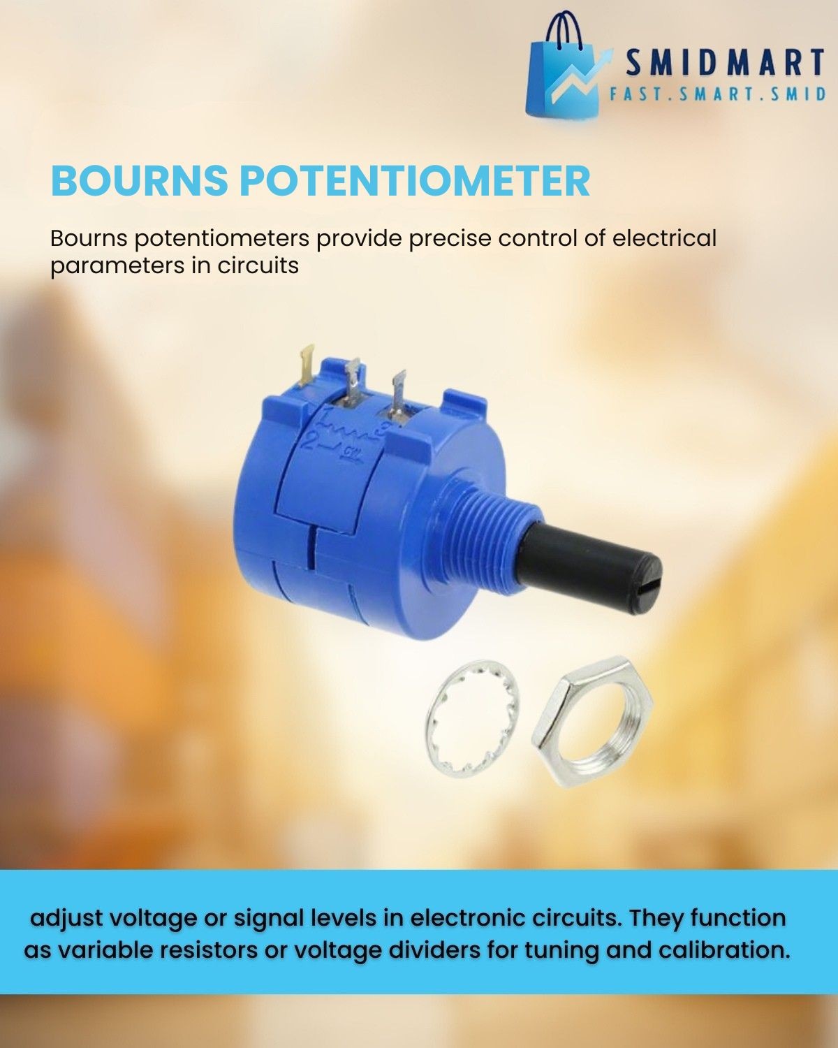
Fine-tune with precision!
Bourns Potentiometers offer reliable control for signal adjustment, tuning, and calibration in any circuit. Trusted performance, compact design.
https://smidmart.biz/6nwBE
#Bourns #Potentiometer #Electronics #CircuitDesign #TechTools
Atari 2600 Controller Shield PCB Revisited
As previously mentioned in my Atari 2600 Controller Shield PCB Build Guide the PCB doesn’t work so well with paddle controllers due to the way they are wired up.
This is an update to the PCB to allow the paddles to be used in a very similar way to the original Atari 2600.
Warning! I strongly recommend using old or second hand equipment for your experiments. I am not responsible for any damage to expensive instruments!
If you are new to Arduino, see the Getting Started pages.
PCB Update
This is basically the PCB design as described here: Atari 2600 Controller Shield PCB Design but with the addition of a resistor and capacitor in the paddle circuit as shown below.
These are the values used in the original Atari circuit as can be found in the following references:
- Atari 2600 main circuit: https://atariage.com/2600/archives/schematics/Schematic_2600_Low.html
- Atari 2600 paddle circuit: https://atariage.com/2600/archives/schematics/Schematic_2600_Accessories_Low.html
- Details of programming for paddles: “Stella Programmer’s Guide” section 12.1, TIA section 8B, Figure 8.
These also describe the operation of the TIA and paddle INPUT circuit:
The block diagram for the TIA shows the transistors mentioned, that are controlled by D7 in VBLANK.
The basic idea being described is that setting D7 turns on the transistors that will drop the voltage from the capacitor to zero. Then the capacitor will charge again and the time it takes to charge depends on the position of the paddle, which is connected to a 1M variable resistor. By measuring the time it takes to charge the capacitor back up, the position of the paddle can be determined.
From all this, we can conclude that the required approach for an Arduino should be as follows (assuming the paddles are connected to analog INPUT ports):
SET pin to OUTPUT
SET pin to LOW
SET pin to INPUT
Start timer
WAIT WHILE (voltage on the analog INPUT pin is NOT HIGH)
Stop timer
This works because the ATmega328P’s analog input ports (at least A0 to A5) can also be used as digital input and output ports.
Note: the Arduino reference documentation states that if swapping from digital output to analog input, then the mode should be explicitly set prior to any calls to analogRead (see “caveats” here).
Build Steps
Solder the components in the following order:
- Resistors
- Capacitors
- Arduino headers
- 9-way D-type connectors
Testing
I recommend performing the general tests described here: PCBs.
The following sketch will read the value of one of the paddle controllers, implementing the algorithm described above.
#define PAD_PIN A0

#define RAW_MAX    950
#define RAW_SHIFT  7
#define RAW_OFFSET 3
#define RAW_BREAK  150000

unsigned long atariRawAnalogRead (int pin) {
  unsigned long start = micros();
  pinMode(pin, OUTPUT);
  digitalWrite(pin, LOW);
  pinMode(pin, INPUT);
  while ((analogRead(pin)<RAW_MAX) && (micros()<(start+RAW_BREAK)))
   {}
  return (micros() - start);
}

int atariAnalogRead (int pin) {
  unsigned long val = atariRawAnalogRead(pin) >> RAW_SHIFT;
  if (val < RAW_OFFSET) {
    return 1023;
  } else if (val < 1023+RAW_OFFSET) {
    return 1023-(val-RAW_OFFSET);
  } else {
    return 0;
  }
}

void setup() {
  Serial.begin(9600);
}

void loop() {
  Serial.print(atariRawAnalogRead(PAD_PIN));
  Serial.print("\t");
  Serial.print(atariAnalogRead(PAD_PIN));
  Serial.print("\t");
  Serial.println(analogRead(PAD_PIN));
}
The configuration values at the top are determined through a bit of trial-and-error, noting the following:
- A single reading could take up to 150 mS.
- The maximum analog reading corresponds to a voltage of around 4.6V, which is around 940 out of 1023.
- Timing the charging using microseconds gives more resolution, especially at the quicker end.
- Shifting the measurement >>7 turns the up to 150,000 value into a value of up to 1170.
- The residual readings are largely in the range 3 to 1170 now, so a subtraction is required to drop that down to 0, and the top reading needs capping at 1023 to match that returned by analogRead().
- Reversing the sense of the readings means that clockwise reads higher than anticlockwise.
- Note: if not controller is plugged in, then the while loop would never complete, so a breakout timer value is provided set to the expected maximum of around 150mS.
The Arduino functions are relatively slow compared to direct register access, but as the time out involved is up to 150mS, I’m not too worried about trying to speed up the Arduino calls.
If I was attempting to read all four paddle controllers at the same time, some optimisation would be required. It might even be worth attempting to read them using a timer interrupt and a sampling routine.
- Update: This has been described here: Atari 2600 Controller Shield PCB Revisited – Part 2
If this was to be used properly, some averaging of values would also be required.
Other PCB Notes
- This PCB still works fine with keypad controllers. The additional resistor and capacitor does not affect the keypad scanning function.
- This PCB also still works fine with joysticks, as the digital lines have not be altered.
- It is possible to use this PCB with the “additional resistor” method described in Atari 2600 Controller Shield PCB Build Guide. This requires installing a resistor where the capacitor is meant to go and shorting the existing resistor link together.
Find the updated PCB on GitHub here.
Closing Thoughts
There are now several approaches that can be used to read Atari paddle controllers from an Arduino.
- Doctor the wiring of the paddles themselves to internally connect the potentiometer to the 5V and GND line, then connect it directly to an Arduino analog input like any other potentiometer.
- Use the approach described in Atari 2600 Controller Shield PCB Build Guide to add a resistor and make a variable potential divider, adjusting the read values in software.
- Use the approach described above to time the charging of a capacitor, mirroring how the original Atari circuit and TIA would have worked.
Kevin

Everything you ever (or never) wanted to know about Potentiometers in this >200 pages Handbook by Bourns from 1975.
Fun, how it changes from serious to comic style in chapter 9: TO KILL A POTENTIOMETER
#electronics #potentiometer #historical #book #handbook #guide
ESP32 S3 DevKit Experimenter PCB Build Guide
Here are the build notes for my ESP32 S3 DevKit Experimenter PCB Design.
Warning! I strongly recommend using old or second hand equipment for your experiments. I am not responsible for any damage to expensive instruments!
If you are new to electronics and microcontrollers, see the Getting Started pages.
Bill of Materials
- ESP32S3 DevKit Experimenter PCB (GitHub link below)
- ESP32S2 DevKitC (official or clone – see ESP32 S3 DevKit)
- MIDI Circuit:
- 1x H11L1 optoisolator
- 1x 1N4148 or 1N914 signal diode
- Resistors: 1x 10Ω, 1x 33Ω, 1x 220Ω, 1×470Ω
- 1x 100nF capacitor
- Either: 2x MIDI DIN sockets (see photos and PCB for footprint)
- Or: 2x 3.5mm stereo TRS sockets (see photos and PCB for footprint)
- Pin headers and jumpers
- Optional: 6-way DIP socket
- Audio Output Circuit:
- Resistors: 2x 1K, 2x 2K
- 2x 10uF non-polar capacitors
- 2x 33nF ceramic capacitors
- 1x 3.5mm stereo TRS socket
- Power Circuit:
- 1x 7805 regulator
- Electrolytic Capacitors: 1x 100uF, 1x 10uF
- 1x 100nF Ceramic Capacitor
- SPST switch with 2.54mm pitch connectors
- 2-way header pins
- 2.1mm barrel jack socket (see photos and PCB for footprint)
- 8x 10K potentiometers (see photos and PCB for footprint)
- Optional: 2x 22-way pin header sockets
- Additional pin headers or sockets as required
Each circuit module is effectively optional. The position of the 22-way headers will depend on which type of module is used. The clone versions are 1 pin row wider than the official version.
There are some solder-bridge configuration options too, which will be discussed later.
Build Steps
Taking a typical “low to high” soldering approach, this is the suggested order of assembly:
- All resistors and diode.
- DIP socket (if used) and TRS socket(s).
- Disc capacitors.
- Switch
- Jumper and pin headers.
- 22-way pin sockets (if used).
- Non-polar and electrolytic capacitors.
- 7805 regulator.
- Potentiometers.
- DIN sockets.
Here are some build photos for the MIDI DIN version of the board. If using MIDI TRS sockets, then these can be installed at the same time as the audio socket.
If using 22-way headers for the DevKit, then the position will depend on which type of DevKit module is being used. In the photo below, I’ve installed 3 sets of 22-way headers to allow me to use either a clone or official module.
The remaining components can almost be installed in any order that makes sense at the time.
Once the main build is complete, two additional capacitors are required for the audio PWM output circuit. Two 33nF capacitors should be soldered across the 1K resistors. This is probably best done on the underside of the PCB as shown below.
Ignore the red patch wire. I managed to cut through a track whilst clipping the excess leads after soldering.
Configuration Options
The following are configurable and can be set by using pin headers and jumpers; solder bridges; or possibly wire links.
- UART for MIDI – pin header + jumpers.
- Audio Output – can be disconnected by breaking solder jumpers on rear of the board under 1K/2K resistors.
- GPIO used for RV3 and RV8 – can be set using solder jumpers on rear of the board under RV3 and RV8.
Testing
I recommend performing the general tests described here: PCBs.
WARNING: The DevKit can be powered from either the USB sockets or the new power circuit, but not both at the same time.
The sample application section includes some simple sketches that can be used to test the functionality of the board.
PCB Errata
There are the following issues with this PCB:
- I should have oriented the DevKit the other way up so that the USB sockets were on the edge of the board, not overhanging the prototyping area!
- The Audio filter requires additional capacitors (see notes).
Enhancements:
- None
Sample Applications
Analog Potentiometers
The following will read all 8 pots and echo the values to the serial monitor.
void setup() {
  Serial.begin(115200);
}
void loop() {
  for (int i=0; i<8; i++) {
    int aval = analogRead(A0+i);
    Serial.print(aval);
    Serial.print("\t");
  }
  Serial.print("\n");
  delay(100);
}
Audio PWM Output
The following will output a 440 Hz sine wave on the PWM channel on GPIO 15. Change to 16 to see the other one.
int pwm_pin = 15;#define NUM_SAMPLES 256uint8_t sinedata[NUM_SAMPLES];#define PWM_RESOLUTION 8#define PWM_FREQUENCY 48000#define TIMER_FREQ 10000000#define TIMER_RATE 305#define FREQ2INC(f) (f*2)uint16_t acc, inc;void ARDUINO_ISR_ATTR timerIsr (void) { acc += inc; ledcWrite (pwm_pin, sinedata[acc >> 8]);}hw_timer_t *timer = NULL;void setup () { ledcSetClockSource(LEDC_AUTO_CLK); for (int i=0; i<NUM_SAMPLES; i++) { sinedata[i] = 127 + (uint8_t) (127.0 * sin (((float)i * 2.0 * 3.14159) / (float)NUM_SAMPLES)); } timer = timerBegin(TIMER_FREQ); timerAttachInterrupt(timer, &timerIsr); timerAlarm(timer, TIMER_RATE, true, 0); ledcAttach(pwm_pin, PWM_FREQUENCY, PWM_RESOLUTION); inc = FREQ2INC(440);}void loop () { }I’m getting a pretty good signal with a 33nF filter capacitor, but the signal still retails some bias. I’m getting a Vpp of around 1.1V.
But it starts out with a swing from around -200mV to +900mV. But this slowly improves over time and after a few minutes is much closer to a nominal -500mV to +600mV. I guess that is probably my cheap capacitors!
MIDI
Most of the MIDI monitors, routers and sending projects I have should work with the MIDI setup. In the default configuration, using UART0 (GPIO 43/44) for MIDI, that appears as Serial0 or the default MIDI configuration (more on serial ports on the ESP32S3 here: ESP32 S3 DevKit).
So the Simple MIDI Serial Monitor should just work and anything sent to the board should:
- Illuminate the on-board (RGB) LED.
- Echo back out to the MIDI OUT port.
Here is the full test code:
#include <MIDI.h>

MIDI_CREATE_DEFAULT_INSTANCE();

void setup() {
  MIDI.begin(MIDI_CHANNEL_OMNI);
  pinMode (LED_BUILTIN, OUTPUT);
}

void loop() {
  if (MIDI.read()) {
    if (MIDI.getType() == midi::NoteOn) {
        digitalWrite (LED_BUILTIN, HIGH);
        delay (100);
        digitalWrite (LED_BUILTIN, LOW);
    }
  }
}
Note: as the MIDI is (probably) hanging of UART0 which is also routed to the USB “COM” port, it will be easier to upload via the USB “USB” port. This won’t clash with the MIDI circuitry on UART0.
Closing Thoughts
I seem to be having a run of “doh” moments with a few of these PCBs, but then that is the price I pay for taking shortcuts by only designing them in my head rather than prototyping them first!
But arguably, it is still a lot easier using a soldered PCB than attempting to build the various elements on solderless breadboard, so in a way that is what these prototypes are largely for.
So apart from the filter issue which is actually fairly easily solved, this seems to work pretty well.
Kevin
ESP32 S3 DevKit Experimenter PCB Design
This a version of the ESP32 WROOM Mozzi Experimenter PCB for the latest ESP32-S3 DevKitC board I’ve found.
For the background on the boards themselves, see my notes here: ESP32 S3 DevKit.
Warning! I strongly recommend using old or second hand equipment for your experiments. I am not responsible for any damage to expensive instruments!
If you are new to Microcontrollers, see the Getting Started pages.
The Circuit
This is mostly just breaking out the pins of the ESP32S3 DevKitC to header pins, but there are a couple of additional features too:
- There are additional rows of headers. The idea is to support the official and clone boards, which means coping with the fact the clone boards are 1 row of pins wider than the official boards.
- There is MIDI IN and OUT with jumpers to select UART0 or UART1.
- There is a stereo PWM output circuit (see notes below).
- There are 8 potentiometers connected to ADC1.
- There is a 7805 or equivalent regulator to provide power if required.
One slight complication is the possibility that GPIO3 (ADC1_CH2) is required as a STRAPPING pin or that GPIO8 (ADC1_CH7) is required for I2C (more in the previous post) so there is a solder bridge option for either of them to switch over to GPIO10 (ADC1_CH9) instead.
The complete GPIO usage is as follows:
GPIO0On board BOOT buttonGPIO 1-8Potentiometer 1-8GPIO 10Optional replacement for GPIO 3 or 8GPIO 15, 16PWM audio outputGPIO 43, 44MIDI if UART0 is selectedGPIO 17, 18MIDI if UART1 is selectedGPIO 1-20Analog breakout area*GPIO 21, 38-49Digital breakout area*GPIO 38 or 48Onboard RGB LED* As already mentioned some of these have alternative or preferred functions.
Audio PWM Output
I based this on the output circuit for my ESP32 WROOM Mozzi Experimenter PCB Design, but I was forgetting that the original ESP32 has a DAC and so only requires a potential divider to reduce the voltage levels and a capacitor to remove the DC bias.
The ESP32S3 does not have a DAC, so the output will have to be via PWM if no external DAC is added. This means this output circuit really needs a low-pass filter to smooth out the pulses from the PWM signal.
That hasn’t been included in the design, but can be implemented by adding capacitors across the terminals of the 1K resistors, as shown below.
Following the discussion from Arduino PWM Output Filter Circuit, we can see that a 2K/1K potential divider can (loosely) be treated as a ~666K resistor for the purposes of a low-pass filter calculation. So this gives me various options in terms of capacitor size as follows.
ResistorCapacitorRoll-off frequency666K10nF24 kHz666K33nF7 kHz666K68nF3.5 kHz666K100nF2.4 kHzThe greatest smoothing will come with the lowest cut-off, but 2.4kHz or 3.5kHz will limit the higher audio frequencies somewhat. But a 10nF might not give me enough smoothing.
It will also depend somewhat on the PWM frequency chosen. The higher, i.e. above the audio frequency range required, the better.
I’ll start with adding 33nF and see how that looks then might change with some experimentation.
If an external DAC is used, then there are solder jumpers provided that can be broken to disconnect this part of the circuit anyway.
PCB Design
I initially considered only breaking out GPIO pins that weren’t being used for additional functions, but then decided I’d just break them all out alongside the prototyping area. Any pins that might be problematic or have an existing function on the board are labelled in brackets – e.g. (GPIO 43).
The solder jumpers for the GPIO/ADC choices are on the underside of the board.
As previously mentioned, the headers are arranged such that it will support the official DevKitC or the slightly wider clones.
The jumper for UART selection for MIDI can serve as a “disable MIDI to allow use of the serial port” function too if required.
There is also a twin jumper option for direct 5V input instead of going via the barrel jack and regulator.
Closing Thoughts
The omission of the capacitors in the PWM filter is a small annoyance, but it is relatively easily fixed.
Apart from that, there is a fair bit included on this board. It should serve as a good platform for further experimentation.
Kevin
Duppa I2C MIDI Controller 3D Print Case
This is a simple 3D printed case for my Duppa I2C MIDI Controller PCB.
https://makertube.net/w/nf7u1sYBRRzj2TUBRduQC2
Warning! I strongly recommend using old or second hand equipment for your experiments. I am not responsible for any damage to expensive instruments!
If you are new to microcontrollers, see the Getting Started pages.
Parts list
- Duppa I2C MIDI Controller
- USB-C lead or serial MIDI.
- MIDI device
OpenSCAD Design
This uses some of the techniques from my Raspberry Pi 2,3,4 A+/B+ Synth Cases to define a basic box, then some cut-outs, and then to split the box and add some overlapping “lips” for a snap-fit.
There a number of functions to achieve this, but some of them are just collecting together the others in the right sequence.
- rounded – a basic “rounded” box module.
- standoff – the PCB supports.
- build_lips/build_lip – as expected, creates the overlapping lips. There is a parameter (solid) which determines if the lip is added to or subtracted from the case.
- base – the main box shape, less the actual top.
- top – the top plate that includes holes for the potentiometer and the LED ring.
- box – uses base() and top() to build a complete box.
- box_base/box_top – uses box and an intersection to produce the two halves of the main box.
At the top level box_base, box_top and standoff (four times) actually builds the complete case.
In terms of assumptions about the build:
- Most importantly, this assumes the use of PH5.0 headers to mount the Waveshare Zero device.
- It also assumes the use of a serial MIDI TRS socket.
- It should allow for M3 spaces and is build to assume two sets of 10mm spacers as described in the Build Guide.
Notes on printing:
- I found getting adhesion for the top with all those circular holes quite a challenge. In the end I increased the bed temperature and slowed the print right down to around 40% for the first layer and that seemed to improve thing quite a bit.
- Once complete I had to tidy up the LED holes a little by hand with a 2.5mm drill bit.
- The additional tag above the USB socket is quite delicate, so care is needed when snapping the case together.
Errata/Improvements:
- For my own build, the potentiometer shaft doesn’t stick out as much as I’d like. It is hard to find a knob that doesn’t have to be altered to fit and stay in place.
- I did wonder about using a thinner layer of 3D print over the LEDs rather than complete holes. I might still try that as an option to see how it works.
Closing Thoughts
This is a little tall, but I’m not sure what, in reality I could do about that. There might be some option for shrinking it a little, especially if the Waveshare Zero RP2040 is soldered directly to the PCB. But it would only save, maybe up to 6 mm in height, so it is probably not worth the effort.
But apart from that, this seems to have come out really well. The holes the LEDs I thought were perhaps a bit of a compromise, but actually they seem to work fine.
Kevin
Duppa I2C MIDI Controller PCB Build Guide
Here are the build notes for my Duppa I2C MIDI Controller PCB.
Warning! I strongly recommend using old or second hand equipment for your experiments. I am not responsible for any damage to expensive instruments!
If you are new to microcontrollers, see the Getting Started pages.
Bill of Materials
- Duppa I2C MIDI Controller PCB (GitHub link below)
- Waveshare Zero format dev board
- 1x Duppa Small RGB LED Ring
- 10KΩ potentiometer
- 5-pin plug and lead (see photo).
- 1x 100nF ceramic capacitor
- Optional: 1×10Ω, 1×33Ω resistor
- Optional: 1x 3.5mm stereo TRS socket – PCB mount (see footprint and photos)
- Optional: 2x 9-way header sockets. Ideally low-profile, PH5.0 sockets.
There are a range of possibilities for the potentiometer, so one has to consider if mountings are required or if a knob will be used. These are some of the pots I could have used:
I used the one with a nut in the end and plan to add a knob at some point.
On that lead… The Duppa ring is described as requiring a “5-way Molex Picoblade, 1.25mm pitch” connector. The lead I ended up with was described on an online, overseas marketplace, as “JST 1.25mm” which I’m not sure is strictly a thing, but that is what worked for me.
Build Steps
Taking a typical “low to high” soldering approach, this is the suggested order of assembly:
- Resistors and diode.
- Disc capacitors.
- TRS socket (if used).
- If using headers for the devboard, now is a good time to solder those.
- Potentiometer.
- Duppa connector cable.
Be sure to get the connector cable the right way round. For the colouring of the cable above, and orientation of the pins, the I2C connectors ended up being the red and black ones for me. More about that in a moment.
Here are some build photos.
The cable has to be cut and then positioned to correctly align with the positions of the wires on the Duppa connector. The following shows which wires align to which solder pads and the position in the connector.
Once all soldering is complete, I used 8x 10mm M3 spacers as shown below.
I’m planning on designing an enclosure that the above posts will slot into. You may need different senses and sizes of spacers depending on your final arrangements.
Testing
I recommend performing the general tests described here: PCBs.
Note that the LED ring is configured using solder jumpers as described previously, for S1, S5 and to use pull-ups, as shown below.
PCB Errata
There are the following issues with this PCB:
- None at this time.
Enhancements:
- The schematic already supports MIDI IN in addition to MIDI OUT, so at some point I could add that too.
Sample Applications
This is designed for use with my Duppa I2C MIDI Controller – Part 4. The Arduino code for that works directly when used with a Waveshare Zero RP2040 with the following configuration:
#define WAVESHARE_RP2040

#define MIDI_USB
#define MIDI_SER

#define LED_PER_CC
#define LED_SCALE_TO_RING

#define CC_POTENTIOMETER
#define PIN_ALG A3
#define MAX_POT_VALUE 1023
The full code is available on Github here.
Closing Thoughts
I’m really pleased with how this turned out. These LED rings are really neat!
Now on to that case…
Kevin
#controlChange #define #midi #pcb #potentiometer #WaveshareZero
Duppa I2C MIDI Controller PCB Design
This is the design for a simple carrier PCB for a Waveshare Zero format microcontroller and a Duppa small LED Ring. It is essentially a PCB version of Duppa I2C MIDI Controller – Part 4.
Warning! I strongly recommend using old or second hand equipment for your experiments. I am not responsible for any damage to expensive instruments!
If you are new to microcontrollers, see the Getting Started pages.
The Circuit
This connects a Waveshare Zero format board to a MIDI IN and OUT interface and a potentiometer. There is a header required to connect to the Duppa Small LED ring.
The following IO pins are used:
Physical PinGPIO: C3, S3, RP2040Function1Power5V2GroundGND3Power3V34GP0, GP1, A3Potentiometer13GP9, GP10, GP5LED SCL14GP10, GP11, GP4LED SDA17GP20, RX, GP1MIDI RX18GP21, TX, GP0MIDI TXFor the RP2040 this is using I2C0 and UART0.
PCB Design
I’ve actually opted not to include MIDI IN functionality in order to keep within a minimal PCB footprint. I’m aiming to have it occupy essentially the same space as one of the small Duppa LED rings itself. I’m also only support MIDI OUT via a TRS jack.
But I have attempted to ensure that both the Waveshare USB socket and TRS socket will protrude enough to be brought out to the edge of a case.
I’ve included a 2.54mm pitch set of header pads that I plan to solder a connecting wire to for the Duppa ring.
Closing Thoughts
I was in two minds about including MIDI IN. It is nice to be able to use this to merge into an existing MIDI stream, but then I also considered that it would probably be used just as a controller in most cases, so went with the small PCB footprint.
I also considered the four control options I’ve experimented with so far. In the end I decided I still liked having an absolute-value potentiometer for a MIDI Controller like this over either a rotary encoder or an endless potentiometer, so that is what I’ve used.
Kevin
Duppa I2C MIDI Controller – Part 4
This is revisiting my Duppa I2C MIDI Controller this time using a Waveshare Zero format device.
- Part 1 – getting to know the devices and testing them out.
- Part 2 – adding MIDI to the LED ring and I2C encoder.
- Part 3 – adding normal encoder, plain potentiometer, and endless potentiometer control.
- Part 4 – revisits the idea with Waveshare Zero format devices and adds USB MIDI.
Warning! I strongly recommend using old or second hand equipment for your experiments. I am not responsible for any damage to expensive instruments!
If you are new to Arduino, see the Getting Started pages.
Parts list
- Waveshare Zero ESP32-S3 or RP2040.
- DuPPa small RGB LED Ring.
- 10K potentiometer.
- Bespoke hook-up wires (available from duppa.net).
- Optional: 3V3 MIDI Interface.
- Breadboard and jumper wires.
Waveshare Zero, Duppa LED Ring, Potentiometers
I’m planning on being able to use any Waveshare Zero format board that I have (so that includes ESP32-S3, ESP32-C3 and RP2040) with the Duppa Ring so that means finding common pins to support I2C.
From the various pinouts (see Waveshare Zero, Pimoroni Tiny, and Neopixels) I can see I can use two pins in the bottom right-hand (with the USB connector at the top) corner of the board.
I’ll also need an analog connection and potentially connecting RX/TX to MIDI.
The various pins I’ll be using are as follows:
PinFunctionESP32-S3ESP32-C3RP204015V2GND33V34ADCGP1GP0GP29/A313SCLGP10GP9GP514SDAGP11GP10GP417RXGP44GP20GP118TXGP43GP21GP0Note, I’m not using physical pins 11 and 12, even though they also support I2C, as for the RP2040, these are on I2C bus 1, not 0 (see note later).
As the Pimoroni Tiny2040 is largely compatible too, that could also be used, but it will be physical pins 11 and 12, corresponding to GP5 and GP4, and 15 and 16 for GP1, GP0 (RX,TX).
The LEDs on the LED ring are powered from 5V, which comes directly off the Waveshare Zero USB port. The logic “VIO” is powered from 3V3.
The Code
I2C LED Ring
As the I2C pins to be used are configurable, this means changing the Duppa example code (and any other Arduino code) to initialise the I2C bus on specific pins as follows:
Wire.begin(11,10);    // SDA, SCL for ESP32-S3
Wire.begin(10,9);     // SDA, SCL for ESP32-C3
Using the ESP32 Arduino Core, there is a specific board entry for the Waveshare Zero ESP32-S3. There isn’t one for the ESP32-C3 so I just used “ESP32C3 Dev Module”.
I used the Arduino core for RP2040 from here rather than the official core: https://github.com/earlephilhower/arduino-pico
But the I2C initialisation is a little different.
  Wire.setSDA(4);
  Wire.setSCL(5);
  Wire.begin();
If I’d have been using GP6 and GP7, then these would have required the initialisation of Wire1 rather than Wire with the RP2040 core.
Note: to use the serial port once a sketch has been loaded onto the board, requires the following to be set (via the Arduino Tools menu):
USB CDC On Boot -> Enabled
Once again, I’ve soldered the jumpers on the LED ring to enable pull-ups and set the address for S1 and S5, so that has to be changed in the demo code too.
Analog Potentiometer
In terms of analog read, the ESP32 has a resolution of 0..4095 compared to the Arduino’s 0..1023, so that has to be taken into account when calculating the MIDI CC values.
To do this, the reading has to be divided by the ratio of Pot Range / 128.
int newpot = algpot.avgeAnalogRead(PIN_ALG) / ((MAX_POT_VALUE+1)/128);
Serial MIDI
For these boards, the serial port has to be specified. There are different options depending on the board being used (more here).
To use the pins nominally designated as RX/TX on all of these boards, use:
// ESP32-S3 GP43,GP44 or ESP32-C3 GP20,GP21
MIDI_CREATE_INSTANCE(HardwareSerial, Serial0, MIDI);
// RP2040 GP1,GP0
MIDI_CREATE_INSTANCE(HardwareSerial, Serial1, MIDI);
It is a quirk of the RP2040 Arduino core that UART0 appears on Serial1 and UART1 on Serial2. Serial0 does not exist but USB is Serial (more here).
Also, for the RP2040 the pins can be changed prior to calling MIDI.begin() if required as follows:
Serial1.setRX(rxpin);
Serial1.setTX(txpin);
MIDI.begin();
MIDI USB
I want to make this a fairly stand-alone MIDI USB device, so for the ESP32 and RP2040 this means using the TinyUSB stack. There is an Adafruit library for Arduino that supports both and also works with the Arduino MIDI Library. References:
- Adafruit_TinyUSB – https://github.com/adafruit/Adafruit_TinyUSB_Arduino/tree/master
- USB MIDI Transport – https://github.com/lathoub/Arduino-USBMIDI (for AVR)
- Arduino MIDI Library – https://github.com/FortySevenEffects/arduino_midi_library
I’ve cribbed most of the code from: https://github.com/adafruit/Adafruit_TinyUSB_Arduino/blob/master/examples/MIDI/midi_test/midi_test.ino
And added the appropriate parts to my own midiSetup() and midiLoop() functions.
MIDI USB – ESP32-S3
For this to work on the ESP32-S3, the board settings (via the Arduino Tools menu) need to be changed as follows:
USB CDC On Boot -> Enabled
USB Mode -> USB-OTG (TinyUSB)
USB Firmware MSC On Boot=Disabled
USB DFU On Boot=Disabled
Naturally this means USB can’t be used for serial output anymore.
It also means that automatic sketch reset and download often didn’t work for me. It was quite normal to now have to use the BOOT and RESET buttons to get the ESP32 back into listening for a new sketch – not always, but also not uncommon. But this might be some serial port remapping weirdness that often occurs when the USB stack is running on the same microprocessor as the main code…
MIDI USB – RP2040
For the RP2040, the USB stack needs to be changed from the Pico SDK to TinyUSB, so in the Tools menu:
USB Stack -> Adafruit TinyUSB
There are some other RP2040 specific notes here, but I don’t believe they apply unless one is interested in rebuilding the core, default TinyUSB support directly.
USB MIDI – ESP32-C3
I don’t believe USB MIDI works on the ESP32-C3
Adafruit TinyUSB doesn’t seem to anyway and I haven’t looked into what the options might be yet.
Other Notes
I’ve left in all the conditional compilation from Duppa I2C MIDI Controller – Part 3 but for now am just working with potentiometer control.
Pretty much everything is configurable, but the most important config option is to specify the board at the top:
//#define WAVESHARE_ESP32S3
//#define WAVESHARE_ESP32C3
#define WAVESHARE_RP2040
I could probably auto detect from the build settings but for now, this will do.
Other options include GPIO pins, whether to include serial or USB MIDI (or both), and whether to enable MIDI THRU or not.
Closing Thoughts
This is the first go at getting my Duppa controller working on 3V3 Waveshare Zero format boards, and so far it looks pretty good.
For the ESP32-S3 and RP2040 being able to enable MIDI USB is particularly useful. I might see if I can support MIDI THRU across the interfaces, which might be handy for a built-in USB to serial MIDI converter, but for now MIDI THRU is on the same port only.
I’ve not tested this with encoders or the endless potentiometer, but in theory it ought to work. I’d have to add some conditional compilation for GPIO numbers if I want to keep the same physical pins again.
Kevin
#controlChange #duppa #endlessPotentiometer #esp32c3 #ESP32s3 #i2c #midi #potentiometer #rgbLed #rotaryEncoder #rp2040 #WaveshareZero


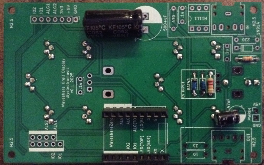
Forbidden Planet “Krell” Display – MIDI CC Controller – Part 2
This revisits my Forbidden Planet “Krell” Display – MIDI CC Controller using my Forbidden Planet “Krell” Display PCB with a Waveshare RP2040 to create more of a “all in one” device.
Warning! I strongly recommend using old or second hand equipment for your experiments. I am not responsible for any damage to expensive instruments!
If you are new to Arduino, see the Getting Started pages.
Parts list
- Updated Forbidden Planet “Krell” Display (see below).
- Completed Forbidden Planet “Krell” Display PCB Build
- Waveshare Zero format device (I’m using an RP2040)
- 4x 6mm brass spacers
- 4x 20mm nylon spacers
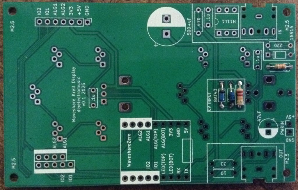
PCB
This requires a built of the Forbidden Planet “Krell” Display PCB with the following:
- 2 potentiometers
- MIDI IN and OUT
I’ve used potentiometers that are their own knob, as they only poke through the casing by around 5mm or so.
If it you are able to get longer shaft pots, then that would probably be worthwhile.
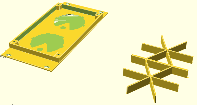
Updated 3D Printed Case
This requires the following from the Krell Display 3D Printed Case:
- 1x Frame
- 2x Inserts (with potentiometer holes)
- 1x EuroRack support
This requires the following options in the OpenSCAD code:
show_frame = 1;
show_quadframe = 0;
show_insert = 1;
show_support = 0;
show_quadsupport = 0;
show_eurorack = 0;
show_eurorack_support = 1;

alg_pot1 = 1;
alg_pot2 = 1;
alg_cv   = 0;
The frame does not really take into account the PCB at present, but I’ve reached the “good enough I want to do something else” stage, so I’ve just added a couple of small cut-outs (using a hacksaw) for the two MIDI sockets, and am content that the components stick out a bit from the back.
This cutout has to be 10.5mm from the end, 6mm wide, and 5mm deep.
At some point I might go back and design a deeper frame that has the cut-outs included and some kind of snap-on back to make it a self-contained box.
But for now, this is left as an exercise for, well, anyone else 🙂
Construction
I’ve used four brass 6mm spacers to screw into the mounting holes in the frame. Then the PCB can be inserted, taking care to squeeze in the 3D printed support around the LEDs and pots, and fixed with 20mm spacers which will also act as “legs”.
The Code
I’ve used a Waveshare Zero RP2040 and Circuitpython for this build. This is a combination of some of the test code used for the Forbidden Planet “Krell” Display PCB but with added MIDI.
The code supports both Serial and USB MIDI.
I wanted an equivalent of the Arduino map() and constrain() functions and didn’t immediate spot them in Circuitpython so wrote my own:
def algmap(val, minin, maxin, minout, maxout):
    if (val < minin):
        val = minin
    if (val > maxin):
        val = maxin
    return minout + (((val - minin) * (maxout - minout)) / (maxin - minin))
This allows me to map the analog read values (0 to 65535) down to MIDI CC values (0 to 127) whilst also allowing for some inaccuracies (I’ve treated anything below 256 as zero for example):
alg1cc = int(algmap(alg1_in.value,256,65530,0,127))
I’ve used the Adafruit MIDI library, which I’m still not really a fan of, but I wanted to include MIDI THRU functionality to allow the controller to sit inline with an existing MIDI stream. But it doesn’t seem to work very well.
I was already only updating the LEDs/MIDI CC if the pot values had changed, to cut down on the number of Neopixel writes required.
I experimented with changing the scheduling of the analog reads and MIDI but that didn’t seem to help very much. In the end I made sure that all MIDI messages queued up in the system would be read at the same time before going back to checking the pots.
    msg = midiuart.receive()
    while (msg is not None):
        if (not isinstance(msg, MIDIUnknownEvent)):
            midiuart.send(msg)
        msg = midiuart.receive()
It will do for now. Moving forward, I might try the Winterbloom SmolMIDI library. If that still doesn’t give me some useful performance then I might have to switch over to Arduino C.
Closing Thoughts
The MIDI throughput is disappointing, but then I’ve never really gotten on with the Adafruit MIDI library. I use it as USB MIDI on Circuitpython is so easy, so will need to do something about that.
I’m still deciding on the PCB-sized supports too. The original seemed to have nicer diffusion of the LEDs, but that could have been the difference between 5mm SMT neopixels and these THT APA106s which seem more directional in the first place.
And I really ought to finish the 3D printed case properly too.
So this is “that will do” for now, but I ought to come back and finish it off properly at some point.
Kevin
#APA106 #circuitpython #ForbiddenPlanet #Krell #midi #midiController #NeoPixel #potentiometer #rp2040 #WaveshareZero
Forbidden Planet “Krell” Display EuroRack Module
This project uses my Forbidden Planet “Krell” Display and the Forbidden Planet “Krell” Display PCB Design but with some slight variations that means it could be EuroRack mounted with a control voltage (CV) input.
This is a DIY module only for use in my own DIY system.
Do NOT use this alongside expensive modules in an expensive rack. It is highly likely to cause problems with your power supply and could even damage your other modules.
https://makertube.net/w/qJqgTxxsEznTuF2DRVZT9o
Warning! I strongly recommend using old or second hand equipment for your experiments. I am not responsible for any damage to expensive instruments!
If you are new to microcontrollers, see the Getting Started pages.
Parts list
- 3D Printed EuroRack format Krell Display unit.
- Waveshare Zero format board – details here.
- Forbidden Planet “Krell” Display PCB built for EuroRack use (see below).
- Additional companion EuroRack power PCB (see below).
EuroRack 3D Print Design
This is an evolution of my original Forbidden Planet “Krell” Display box, but fitting into EuroRack dimensions: 128.5 x 60, which essentially makes it a 12 HP module.
It still takes the same inserts however, but now also includes options for holes for jack sockets or potentiometers:
show_eurorack = 1;
show_eurorack_support = 1;

alg_pot1 = 1;
alg_pot2 = 1;
alg_cv   = 0;
I’ve also included a special “supports” option for use with the PCB and the EuroRack case.
Krell Display PCB – EuroRack Build
To build one of my Forbidden Planet “Krell” Display PCB Designs for use with a EuroRack, follow the previous Build Guide but note the following differences:
- The MIDI circuits are not required when used as a CV input device.
- The lower potentiometer should be replaced with a CV input circuit.
- The upper potentiometer is optional, but I’m omitting it for my build.
- Power will come via the 5V jumper headers from an additional EuroRack power PCB (details below).
- Low-profile (e.g. 9mm high in total) headers should be used for the Waveshare Zero, but once again note the errata about the footprint on the PCB being too wide.
Here are some build photos of a build for EuroRack use. For this build there are only two diodes (the two BAT43) and two resistors (22K and 33K). Also note that none of the 100nF ceramic capacitors are required either.
Both electrolytic capacitors have been soldered into position on their sides as show below.
The Thonkiconn style mono jack shares the footprint are of the lower potentiometer on the LED side of the board, but be sure to get use the correct mounting holes as shown by the orientation below.
Nothing has been soldered to the power jumper yet. See the discussion below for how to link this to the power board.
Krell Display Companion EuroRack Power PCB
Bill of Materials:
- Waveshare Zero “Krell” Display EuroRack power PCB (Github Link below).
- L7805 TO-220 format regulator or equivalent (see discussion below).
- 1x 16-way DIP EuroRack shrouded header.
- 1x 1N5017 Zener diode.
- 2x 47uF electrolytic capacitors.
- 1x 100nF ceramic capacitor.
- 2-way Jumper header socket and pins (probably need extended pins – see discussion).
I’ve opted to use a DC-DC converter with a 7805 physical footprint as shown below.
If a 7805 regulator is used then a heatsink will almost certainly be required. I’ve oriented the regular to allow for a “tab up” mounting which hopefully leaves plenty of room for some kind of heatsink to be used.
Here are some build photos.
There is an option on the PCB to install a 10R resistor as is sometimes recommended for EuroRack modules. From what I’ve read this seems to be to allow it to act as a “fuse” in the case of an incorrectly wired module. As I’ve discussed before (see here) I’m not sure this is so relevant for me, so I’m using the provided solder bypass bridge to leave it out.
Note the orientation of the DC-DC converter.
I’ve used extended pin headers for the power link between the two boards, but due to an error in positioning, they’ve had to be bent over slightly – more on that later.
Physical Build
A completed unit has the following parts:
- 3D printed case, PCB supports, and two “krell” inserts.
- Main PCB built for EuroRack use as described above.
- Power PCB as described above.
- M2.5 spacers and fixings as follows:
- 4x 6mm M2.5 brass fixings.
- 4x 15mm M2.5 nylon fixings.
- 4x M2.5 nylon screws.
The power link between the two PCBs has to be trimmed and slightly bent as shown below.
Once the whole thing is put together, there isn’t room, at least on my build, for the nut to be put on the jack socket. Also, the 6mm and 15mm spacers might be slightly too short, depending on how far off the PCBs the LEDs ended up. Some experimentation and “encouragement” is probably required to get everything together.
The Code
The code is relatively straight forward, and is largely a mix of the analog and neopixel test code from the Forbidden Planet “Krell” Display PCB Build Guide.
One quirk is scaling the analog read from 0..65535 to a useful 0-10 to allow for zero to 10 leds to light up. I’ve allowed for a range of values to be “basically zero” too to allow for some jitter or noise.
As I only write out to the neopixels when something changes, this code seems to be quite responsive.
This requires the following Adafruit Circuitpython Library Bundle libraries:
- neopixel.mpy
- adafruit_pioasm.mpy
- adafruit_pixelbuf.mpy
In fact, the entire Circuitpython code is given below.
import time
import board
import neopixel
from analogio import AnalogIn

cv_in = AnalogIn(board.A3)

pixel_pin1 = board.GP2
pixel_pin2 = board.GP3
num_pixels = 5

pixels1 = neopixel.NeoPixel(pixel_pin1, num_pixels, brightness=0.3, auto_write=False, pixel_order=neopixel.RGB)
pixels2 = neopixel.NeoPixel(pixel_pin2, num_pixels, brightness=0.3, auto_write=False, pixel_order=neopixel.RGB)

col = (80, 35, 0)

lastcv = -1
while True:
    cv = cv_in.value / 256

    if (lastcv != cv):
        lastcv = cv
        led = cv / 25
        for pix in range(5):
            if (pix < led and cv > 5):
                pixels1[pix] = col
            else:
                pixels1[pix] = 0

            if (pix+5 < led and cv > 5):
                pixels2[pix] = col
            else:
                pixels2[pix] = 0

            pixels1.show()
            pixels2.show()
GiHub Resources
There is now an updated version of the OpenSCAD code for the case on GitHub and the PCB and code are also now available.
- OpenSCAD code and STL models: https://github.com/diyelectromusic/sdemp_3dprints/tree/main/KrellDisplay
- PCB: https://github.com/diyelectromusic/sdemp_pcbs/tree/main/WaveshareZeroKrellDisplay
- Code: https://github.com/diyelectromusic/sdemp/blob/main/src/SDEMP/CircuitPython/KrellEuroRackDisplay.py
Closing Thoughts
This isn’t a perfect build in mechanical terms, but I’m not sure I ever do anything perfectly anyway, especially where mechanical things are concerned, but the final result is pretty pleasing.
The video shows it running with a Pimoroni RP2040 in the driving seat. First a potentiometer provides a 0 to 5V input, then I’m using my Educational DIY Synth Thing‘s LFO to provide a 0 to 3V3 input.
Kevin
Duppa I2C MIDI Controller – Part 3
This is a follow up post to Part 2 expanding on the code and adding in some of the alternative control options I mentioned.
- Part 1 – getting to know the devices and testing them out.
- Part 2 – adding MIDI to the LED ring and I2C encoder.
- Part 3 – adding normal encoder, plain potentiometer, and endless potentiometer control.
- Part 4 – revisits the idea with Waveshare Zero format devices and adds USB MIDI.
https://makertube.net/w/ncLFMqBwCUcrrM4r3mHJwd
Warning! I strongly recommend using old or second hand equipment for your experiments. I am not responsible for any damage to expensive instruments!
If you are new to Arduino, see the Getting Started pages.
Parts list
- Arduino Uno/Nano.
- DuPPa small RGB LED Ring.
- 10K potentiometer.
- KY-040 rotary encoder module.
- Bespoke hook-up wires (available from duppa.net).
- Breadboard and jumper wires.
The Circuit
This circuit shows all three control options on the same diagram, but naturally use whichever one you require. There are the following three options:
- Duppa I2C Encoder (from the previous project) on A4, A5 (SDA, SCL).
- Plain potentiometer on A0.
- Rotary encoder on D10, D11, D12.
In addition to the I2C LED Ring on A4, A5 (SDA, SCL) of course.
Here is a separate diagram for the endless potentiometer. I can be used alongside the above, but I’ve drawn it on its own for clarity.
Mine has the pins in the following order: Wiper A, GND, Wiper B, VCC.
The Code
This uses the code from Part 2 as a starting point and adds in some additional features.
The main aim is to add additional control options and then make them selectable in code. There are several definitions at the top of the file. One of them should be uncommented to enable that control option.
//#define CC_ENCODER
#define CC_POTENTIOMETER
//#define CC_I2CENCODER
//#define CC_ENDLESSPOT
Each control method will have some associated functions, but the interface will be hidden away behind these definitions and called from the main code, something like the following.
#ifdef CC_ENCODER
#include <librarycode.h>
... control specific definitions ....

void encSetup() {
// Control specific setup code
}

void encLoop() {
// Control specific loop code
}
#else
void encSetup() {}
void encLoop() {}
#endif
If that control option is not enabled, then it will just end up with the two empty functions.
Normal Potentiometer
This is fairly straightforward. I’m using the averaging technique I’ve mentioned before (details here) and include a counter so that the pot isn’t read on every scan, otherwise it slows down all other processing significantly.
The pot reading is scaled down to 7-bits from the default 10-bit value with a bitshift.
I’ve opted to have a jump if the CC value is updated over MIDI rather than anything more sophisticated, as that is probably the simplest.
All the same display options are available as used previously: one LED per CC; scaled to multiples of the ring size; or scaled to a single ring.
This works quite well with all of them, but probably makes most sense when the MIDI CC range is scaled to a single revolution of the LED ring.
CC_WRAP has no effect when used with a normal potentiometer, as the pot itself does not wrap around.
Rotary Encoder
This is using the same encoder library I’ve used before in my Arduino MIDI Rotary Encoder Controller. This makes the scanning code relatively straight forward.
I’ve refactored out the increment/decrement functions from the I2C encoder code into midiCCIncrement and midiCCDecrement, so these can now be used by both encoder options.
These encoder modules are often switched, but I’m not making use of the switch here.
Once again, all the same display options are available: one LED per CC; scaled to multiples of the ring size; or scaled to a single ring. CC_WRAP can be on or off.
Endless Potentiometer
There is a detailed discussion of how these work here: https://hackaday.io/project/171841-driveralgorithm-for-360-deg-endless-potentiometer
My initial thought was that I could just use one of the wipers, assuming it would go from 0 to full resistance and immediately back to zero, but they don’t – they gradually go from 0 to full resistance and then gradually back to 0 again. See the diagram in the above link.
This means that some processing is required to get a single reading out of them, so I ended up using a library from here:
Well actually, I ended up using the slight variant of the library as used on the “Ottopot” MIDI controller, which can be found here:
In my case I just dropping in the endlesspotentiometer.cpp/h files into my Arduino sketch (swapping any includes from <> to “” in the process). There was one reference to main.h that needed removing, and it required a definition of MAX_POT_VALUE which is 1023 for an Arduino Uno.
Then the code is fairly straight forward as the library is able to give an indication of direction and how much the pot has moved.
One thing to watch out for – I wanted this to be able to act on midiCC in a relative manner, replication the benefits of an encoder, but with a potentiometer, so I needed to know how much the pot had changed and then add that to the current midiCC value, rather than set it directly.
To do this I allowed midiCCIncrement/Decrement to take a parameter – how far to increase or decrease midiCC.
The core code for handling the endless pot was thus:
endpot.updateValues(epot1.avgeAnalogRead(PIN_EALG_1),
                    epot2.avgeAnalogRead(PIN_EALG_2));
if (endpot.isMoving) {
  if (endpot.direction == endpot.CLOCKWISE) {
    midiCCIncrement(endpot.valueChanged);
  } else if (endpot.direction == endpot.COUNTER_CLOCKWISE) {
    midiCCDecrement(endpot.valueChanged);
  }
}
I also turned the potentiometer averaging code into a class of its own so I could also use it here for both analog readings of the endless pot.
It took a bit of experimentation with the sensitivity and threshold settings and how they interacted with the frequency of reading, but I’ve ended up with something that seems to work ok for me.
Summary
Although at the start I said that one of the options should be commented out to select it, in reality, if the devices are all on separate IO pins, then actually they can all be enabled at once.
And it does seem to work pretty well, with all four methods: I2C encoder, plain encoder, potentiometer – all interacting as you might expect they would.
Closing Thoughts
I was quite surprised how usable everything was with all four input methods enabled. I probably wouldn’t recommend it for typical use, but it was a bit of fun.
It is particularly satisfying to sweep through the entire range using the pot with “one LED per CC” enabled, even though scaling a single ring to the potentiometers range makes more sense (to me).
At some point I will try to get several controls up and running.
Kevin
#arduinoNano #duppa #endlessPotentiometer #i2c #ifdef #midi #potentiometer #rgbLed #rotaryEncoder

#Drilling holes and test fitting the #enclosure for my 10 step #sequencer
On the front slope, there are ten #potentiometer, LEDs, and toggle switches. The LED fixtures are still missing.
On the top, unsloped part will be the step selector, inputs and outputs.
At the back side will be the power connector and the power switch.
#diysynth #synthesizer


Client Info
Server: https://mastodon.social
Version: 2025.07
Repository: https://github.com/cyevgeniy/lmst