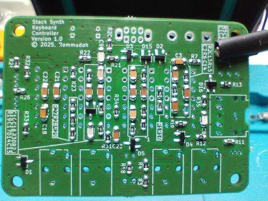
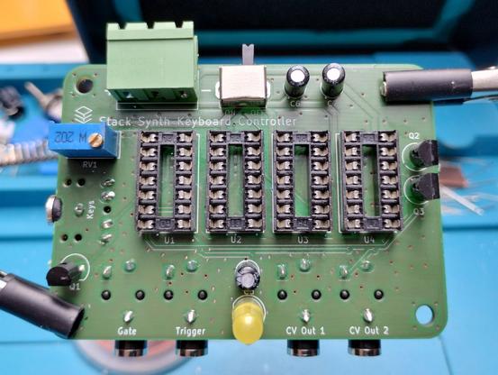
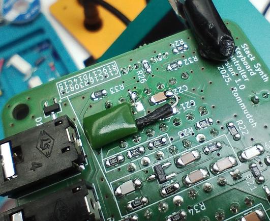
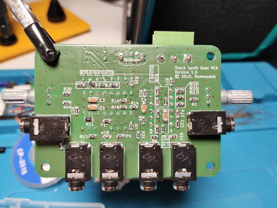
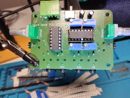
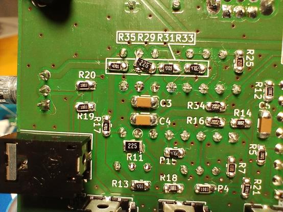
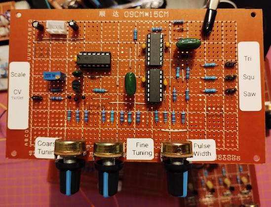
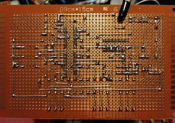
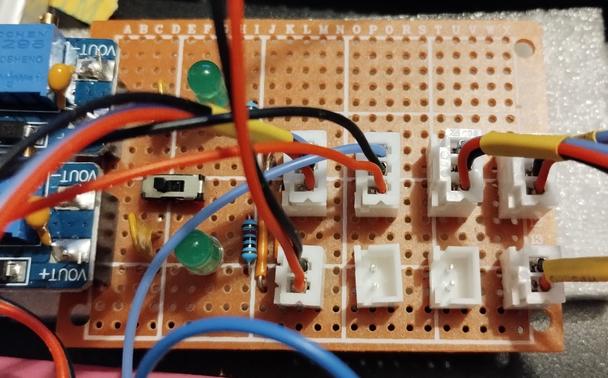
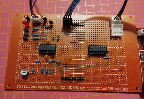
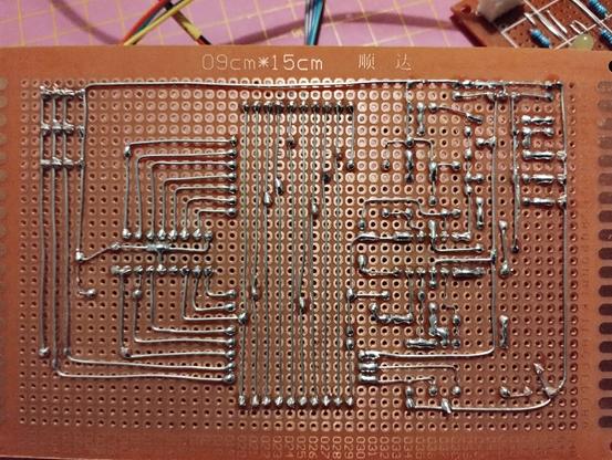
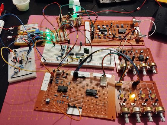
This time my #soldering was a fail. This is supposed to be a #keyboard controller for playing my #StackSynth but the sample and hold part needs rework. The output voltage keeps rising. At first I noticed that I used a ceramic #capacitor where I should've used a polymer one, but this bodge didn't help. Maybe the #TL074 are out of spec (most likely fake ones but worked fine in the other modules) or the FETs are bad...
The keys will be attached using a stereo 3.5mm audio jack, and will be extendable like my perfboard version.
#diysynth #synthesizer #sampleandhold
#TL074
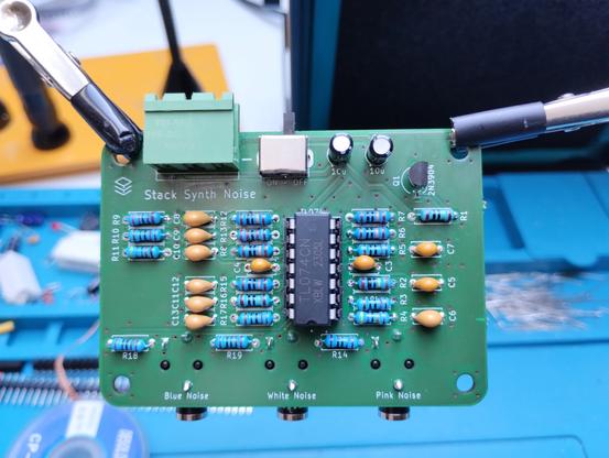
One of the final modules for my #StackSynth project: the #noise generator. It outputs white, blue, and pink noise and uses a #3904 and a #TL074 with a lot of resistors and a couple of capacitors.
It is based on Moritz Klein's video: https://youtu.be/0yB_h_wFkh4
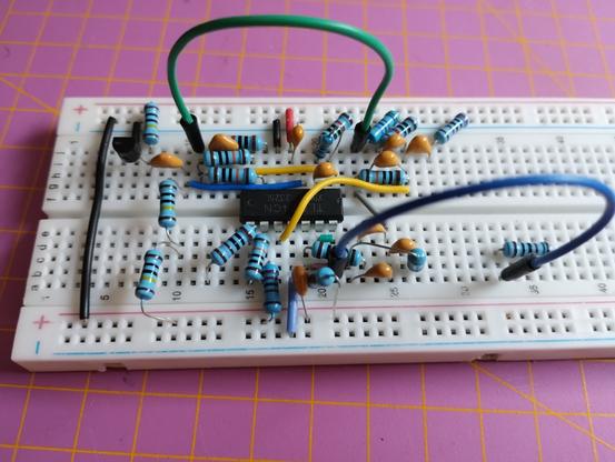
I prototyped it on solderless #breadboard and then designed the #PCB in @kicad and let @aislerhq manufacture them again. It turned out quite nice and sounds great.
#soldering #diysynth #synthesizer #KiCad #pcblayout #MoritzKlein
Finished #soldering another #StackSynth #diysynth module, an important one: the #VCA - together with the ADSR, it makes the output sound much better.
Again, boards were manufactured by @aislerhq and they look nice.
I noticed that I didn't have any 2MΩ 0805 #SMD resistors, but found a couple of larger 1206 2.2MΩ ones in my recycle bin. They don't fit perfectly, but should do until I have the proper ones.
#synthesizer #LM13700 #TL074
Finished #soldering my #VCO #perfboard. It is calibrated to 1V/Octave and outputs sawtooth, square/pulse, and triangle waveforms.
The heart is a #CD40106, using only one of the inverted Schmitt triggers. I tried adding more, but couldn't fit them properly. Maybe if I left out the triangle wave output, which would remove the upper #TL074.
My power supply board is getting full, I should add a few more sockets.
Demo video: https://makertube.net/w/bxShHoDY5cCP7krbjnFgh8
#diysynth #waveform
Finished #soldering the next #perfboard, the #sequencer core with the #CD4017 counter chip and a #TL074 #OpAmp. I have connected the control board and the rest, see a demo here: https://makertube.net/w/mEobXiLn5so6Rpe2zQA16E
After soldering all components, I had the idea of adding a #LED for the gate output. Fortunately it fit very nicely.
Only VCO and LFO are still on solderless breadboards, and I wasted some time searching for a fault turning out being bad connections on the breadboard...
#electronics #diysynth
#finished #soldering the #perfboard. The #TL074 and the #LM13700 are already inserted, too. Will give it a try tomorrow, now is too late.
I forgot to order 120kΩ #resistors, so I used 100kΩ ones and added 20kΩ #SMD resistors on the back side.
While planning the #PCB layout, I sometimes used diagonal traces. At three places they went directly through neighboring solder joints, so I had to insulate them. In future, I'll use them less often.
#diysynth #VCA
