An improved tank circuit EFHW coupler
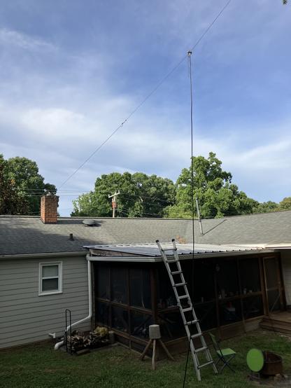
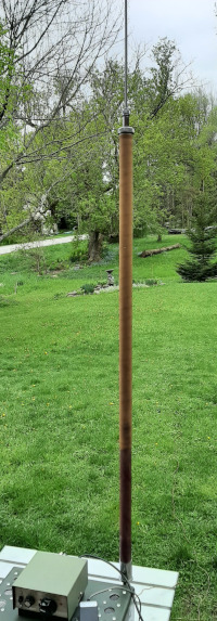
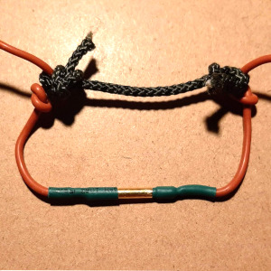
About a month ago Ham Radio Outside the Box posted about “a third way” to match the high impedance at the feedpoint of an End-Fed Half-Wave antenna. A link to the original article is at the bottom of this post. A “30-minute special” was built to prove the concept actually works. It did work fine business (as we say on-air), but that initial implementation had a serious limitation – it was limited to a single band due to the use of a fixed capacitance (a trimmed short length of coax). How could we adapt the basic design to cover multiple bands? Read on to hear about a new improved EFHW coupler that does indeed cover multiple bands.
A QRO(p) coupler
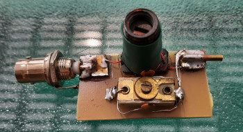
Searching through the vaults containing a vast reserve of assorted electronic components at Ham Radio Outside the Box laboratories (my basement) I unearthed an air-spaced variable capacitor. These now rare items were common in the days of TRF (Tuned Radio Frequency) receivers. For a long time now Superheterodyne circuits have seen the gradual demise of air-spaced variable capacitors.
What’s behind the big knob?
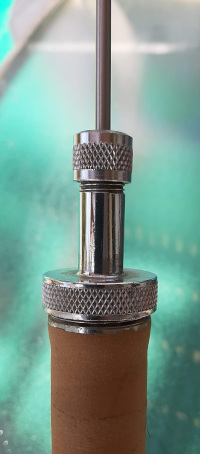
When you look a radio in the face you will usually see that one of the knobs is larger than the rest. That would be what we used to call the “Tuning” knob; nowadays it is more likely to be labeled “VFO”. That would be our first clue as to whether the component behind the front panel is an air-spaced variable capacitor or one of those new-fangled devices called a “Rotary Encoder”. If you turn the knob until you hit an end stop it is a variable capacitor; if it turns freely it is a rotary encoder. For somebody like myself who first gained an interest in radio when capacitors were called “condensers” that is important and useful when deciding whether to purchase an old radio at a yard sale with a view to scavenging its parts.
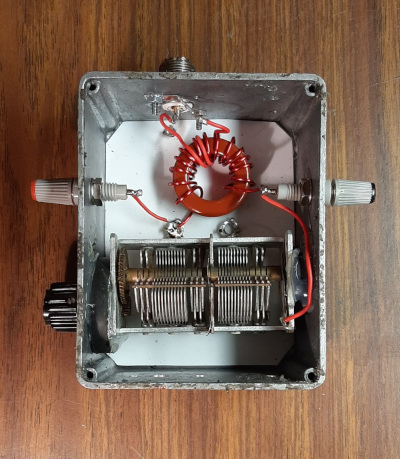
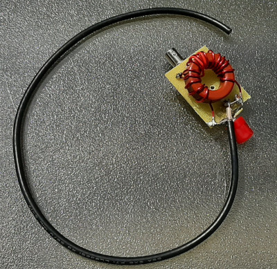
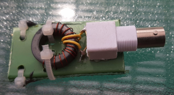
The component I found in the underground vaults is an even rarer device – it has a slow-motion gear drive. That is a valuable feature when tuning a high-Q tank circuit. I re-used the T200-2 powdered iron core and coil windings from the original single-band coupler. Consumer grade AM radio sets often used a thin cord stretched around an elaborate system of pulleys to achieve the same fine adjustment in tuning, but a mechanical gear system is more robust and reliable.
The capacitance range of the “tuning condenser” was measured using my “Almost All Digital Electronics L/C Meter IIB” and those values, along with the fixed value of the toroidal inductor, were plugged into a LibreOffice spreadsheet to find the range of resonant frequencies available with this coupler. My target was 20m, 30m and 40m – the bands I use most frequently. Good luck struck again, my junque box variable capacitor was able to cover those three bands so I got to work building the new coupler.
Construction
There are only two main components – an inductor and a variable capacitor so putting the coupler together didn’t take very long. For expedience I re-used an old Hammond aluminum enclosure from a long forgotten project. I would have preferred a plastic enclosure but I didn’t have a suitable plastic box available. Now that the device has been proven to work I plan to purchase a domestic electrical box from the hardware store. Hammond aluminum project boxes are sturdy and well made, but they have what I perceive to be a design flaw – sloping walls – which makes them unsuitable for projects like this one. Another consideration is that the kind of variable capacitor employed in this project should be electrically isolated from its enclosure because the body of the capacitor is connected to its static plates. We want to prevent stray capacitance or unwanted conductive paths.
This project was built for my “QROp” rig which is a Yaesu FT-891 capable of 100 watts but which I rarely use above 20 watts. I have even used it as a QRP rig by dialing the HF Power setting down to 5 watts. The disadvantage of operating the FT-891 as a QRP rig is the high current consumption. There is very little practical difference in signal strength between 5 watts and 20 watts, but 20 watts might just edge my signal above the noise during poor band conditions. So I am now working on a QRP version.
Working QRP usually involves lightweight station equipment although that isn’t always the case – refer to my post: “My radio is tiny. So why is my POTA backpack so heavy?“. No matter how small your transceiver is, all the ancillary equipment (like a chair, drinking water etc) adds weight to your pack. Lightweight radio gear doesn’t really allow use of heavy variable capacitors. A QRP version of this coupler will replace the heavy, bulky, air-spaced variable capacitor with polyvaricons which are very small and very lightweight.
Incidentally, why are these miniature variable capacitors called “polyvaricons”? Is the name a contraction of “polymer variable condenser“? Condenser? Surely that should be “polyvaricaps”. Now this old codger feels at home!
Polyvaricons scavenged from secondhand AM/FM radiosTip: Polyvaricons are available from various QRP parts suppliers but there is another source that is very convenient and cheaper. I went to a local charity shop recently and bought a couple of budget AM/FM radios for pocket change. The checkout clerk told me I had 7 days to check that the radios actually work and I could return them if they didn’t.
I replied that I guarantee they won’t work in about an hour from now as I am going to tear them apart to use their components!
Polyvaricons usually have several sets of plates some of which are high capacitance and some are low capacitance. To make fine adjustments of the capacitance in a QRP version of this project I plan to exploit this feature. Combined with replacing a bulky SO-239 with BNC connectors, all in a small lightweight plastic project box should reduce the size and weight and make a QRP version suitable for backpacking.
Why not use an L-match?
I believe an L-match, discussed in previous posts, is a more efficient coupler for End-Fed Half-Wave antennas. Unlike the tuned tank circuit design, an L-match does not involve the use of a transformer which introduces potential losses. So why have I gone ahead with a tuned tank circuit coupler instead?
I have corresponded with readers who use L-matches as couplers for EFHW antennas. One thing stands out about L-match couplers – each band requires a separate coupler with a fixed capacitance and fixed inductance. This is not conducive to rapid band changes in the field. An alternative is an L-match tuner employing a variable capacitor and variable inductor. I have built one of these but I am of the opinion that this introduces potential losses due to the switched inductance. Even a variable capacitance introduces the potential for losses because of the way contact is made with the moving vanes.
There is a way to configure variable capacitors to overcome this problem. Builders of small magnetic loops often employ it because even a tiny ohmic resistance can impact loop efficiency. In regard to inductance changes, perhaps plug-in inductors could be used just like in the old days when capacitors were condensers.
This whole series of posts here on Ham Radio Outside the Box documents the pursuit of a highly efficient replacement for the broadband impedance transformer commonly used with EFHW antennas. What is your opinion? I invite your comments on this topic.
Re-read the original post:
https://hamradiooutsidethebox.ca/2025/05/14/matching-an-efhw-antenna-a-third-way/
Help support HamRadioOutsidetheBox
No “tip-jar”, “buy me a coffee”, Patreon, or Amazon links here. I enjoy my hobby and I enjoy writing about it. If you would like to support this blog please follow/subscribe using the link at the bottom of my home page, or like, comment (links at the bottom of each post), repost or share links to my posts on social media. If you would like to email me directly you will find my email address on my QRZ.com page. Thank you!
The following copyright notice applies to all content on this blog.
This work is licensed under a Creative Commons Attribution-NonCommercial-NoDerivatives 4.0 International License.
