#si4703

2025-11-26

Чип, который умеет говорить (SI4703)

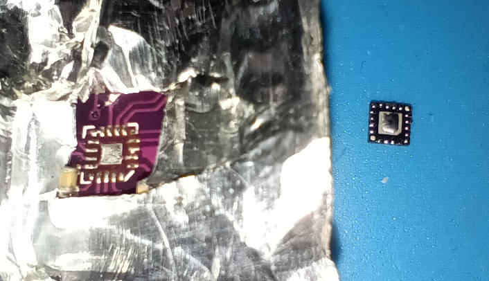
В этом тексте я хотел бы рассказать про свой опыт работы с однокристальным радио приёмникои SI4703 от компании Silicon Laboratories. SI4703 - это миниатюрный настраиваемый FM радио приемник c DSP обработкой, управляемый по I2C, с возможностью принимать бинарные данные от радиостанций по протоколу RDS . Чип производит демодуляцию частотно модулированного сигнала, пропускает его через цифровой гетеродин и выдает на наушники аналоговый сигнал. Тут есть два смесителя: первый аналоговый, второй цифровой. Аналоговый смеситель снимает FM сигнал с несущей. Цифровой смеситель подстраивает цифровой гетеродин на конкретную радиостанцию. Это классический гетеродинный приемник.

habr.com/ru/articles/970446/

#si4703 #i2c #spi #Silicon_Laboratories #sparkfun #FMradio #asic #multimedia #infotainment

Joshua Purba :blobcatphoto:jo@zzncx.top
2025-03-12

LOL nope.

I see that there are a lot of projects that connected the Si4703 3.3V pins directly to Arduino 5V pins and claimed to work.

Not a few, a lot. Weird isn't it? They cannot all be fake.

So I dug deeper. As I was reading more about Si4703, a post by jezo421 in GitHub comment dated 2025-01-04 jumped out to me:

Yesterday I received the Si4703 module from Ali. I had the same problem. I2C communication was OK, but tune did not work. Register Status RSSI was still 0x0000. The problem was HW. Pad 16 on the bottom of the chip was not soldered. It is an analog power supply, so it could not work. The repair was unpleasant, but it was successful :-)

https://github.com/pu2clr/SI470X/issues/4#issuecomment-2570595858

Could it be? That my Si4703 breakout board is from the same batch as jezo421? That my problem was actually caused by bad solder job?

Nothing to lose except time and effort, I tried desoldering the Si4703 chip, and guess what?

Pin 16 (VA = Analog Supply) was dry, no solder. :blobcatangry:

I resoldered it to the breakout. Tried breadboarding with similar setup as before. And it works. IT WORKS. Despite me previously exceeding the absolute max voltage for SCLK, SDIO, RST, and GPIO2 pins.

Solved! Problem = pin 16 not soldered. Solution = desolder the chip and resolder.

Thank you jezo421 :blobhaj_thanks_wow:

So if your Si4703 breakout appears to be not working, or even if you mistakenly connected the pins to 5V, don't give up yet! Your breakout may have the same problem as mine and jezo421, so try to resolder the Si4703 chip!

#Electronics #Arduino #Si4703 #Repair

The Si4703 breakout board covered by aluminium tape with hole on the Si4703 footprint. The Si4703 chip itself had been desoldered and lying bottom-side-up (pads visible) on the right of the breakout board.Close up of the underside of the Si4703 chip. It is obvious that pin 16 (uppermost right) was not soldered. Pin 6 (leftmost bottom) while not ideal at least had some solder.The breakout board after resoldering the Si4703 chip. I am not good at it, so the audio jack is partially melted. This was before I cleaned the plentiful and sticky flux residue. Lots of alcohol and it still feel sticky.Me holding the breakout board with Arduino Nano clone, a logic level converter, the Si4703 breakout board, and external power supply, everything is powered on. Behind the breadboard is the computer monitor, showing Arduino IDE with serial monitor printing logs that shows that everything works now.

Client Info

Server: https://mastodon.social
Version: 2025.07
Repository: https://github.com/cyevgeniy/lmst