#usbcpd

2025-04-05

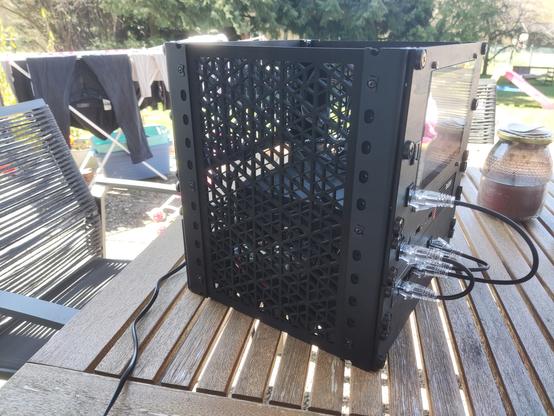
Project #minirack is done :)
The goal was to have a nice "living room capable" 10" rack to hold my #homeasssitant box with a touch display for smart home control, a network switch and a UPS.
And no it is not living in the livingroom now, nor was it planned ;) I could have moved the network wiring to the back/inside, but in the end it needed a little nerd factor.

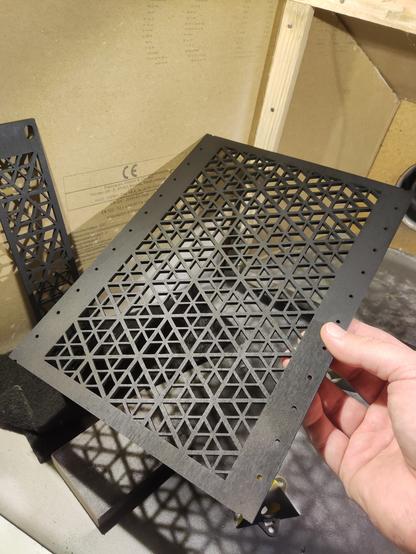
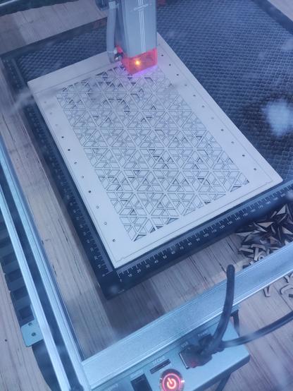
Mostly made from laser cut plywood in #kumiko pattern that I spray painted black, and some 3D printed parts. All self designed/built except for the metal rails in the corners.
And did I mention it's ALL powered by USB-C PD internally? 😍

#homeassistant #smarthome #homeapprovalfactor #lasercut #making #makeoftheday #3dprinting #serverrack #thinkcentre #diy #usbcpd

2025-02-13

No, laptop, don’t try to power yourself off my iPhone. You have power coming in on the other power port… be a good boy and charge my iPhone too… #USBCPD

Clemens aka datadatacop@literatur.social
2025-02-02

Are there any open USB-C PD implementations or configurable trigger chips that also support setting USB-C Alt-Mode (DP) setting?
I'm looking to get a device to not request PD but still enable alt-mode on the link.

#usbc #usbcpd #electronics

2024-07-26

what gyms have USBC power delivery ports on all their cardio equipment

#usbc
#usbcpowerdelivery
#usbcpd

2024-05-28

Any USB-C / Smart Charger / PD experts out there?

Trying to find out how much more $$ it would have cost Staresso to put a smart PD style charger receiver inside their new Discovery II USB-C charging cordless coffee grinder. It appears to have a pretty basic 5V /1A charger, and it does not work with a 35W USB-C charging brick I have, but does work with a Qualcomm Q 18W charger I have.

Does it need a smarter battery too to make rapid charging / PD chargers work?

#usbc #pdcharger #usbcpd

2024-04-12

@AlanSill I’d start with something like this sort of thing:
thepihut.com/products/sparkfun-power-delivery-board-usb-c-qwiic
But… I don’t think 12VDC is part of the normal PD voltages, normally they’d go 5V; 9V; 15V; 19V or something like that, but perhaps they’re configurable (but then, both ends need to agree)

I’m no expert though

#USBCPD

2023-07-11

#soldering project of the day: a USB-C PD power supply for #Nintendo64.
I really like using SMD resistors for #perfboard. It makes the layout very compact and tidy.
#electronics #n64 #powersupply #usbcpd #usbc #powerdelivery

The finished perfboard inside the bottom part of the case. The USB poet lines up with the power cable inlet.Bottom side of the perfboard. The connections are made using tinned copper wireThe connector for the N64 is attached using wires and a JST connectorCloseup of the bottom side of the section next to the USB connection module. There are three 0805 SMD resistors visible.
wow_elec_tronwow_elec_tron
2023-05-29

Completed my latest version of the Light up Shoulder pads ;) 476 x 5050 pixels driven by an with 2 chan parallel out, powered by any powerbank

wow_elec_tronwow_elec_tron
2023-01-30

Presenting the Anubis this took about 24 hours over 4 days to complete from the reels of pixels to this beast of a Its driven by an & powered by a (15w) powerbank & has a dedicated wifi based for animation config

Correl Roushcorrelr@tech.lgbt
2023-01-21

I solved my issues with the beat up barrel jack power adapter for my #Chromebook.

A couple diodes and a 20V #usbcpd trigger board, and I don't have to use that old adapter anymore. Seems to be working really well :blobhaj_sunglasses:

The innards of an upside-down Acer Chromebook 14. A USB-C port has been added with a USB PD trigger board on the right hand side, with wires running through the center under strips of green tape, terminating at a connector to the main circuit board.The side of the closed Acer Chromebook 14, showing a freshly drilled and dremeled USB-C port alongside the HDMI and USB-A ports.
2021-07-19

It’s Super Easy To Build Yourself a USB-C Variable Power Supply These Days

Once upon a time, building yourself a power supply required sourcing all manner of components, from transformers to transistors, knobs, and indicators. These days, everything's a bit more integrated which helps if you're trying to whip something up in a hurry. This build from [Ricardo] shows just how straightforward building a power supply can be.

The build is a simple mashup, starting with a ZY12PDN USB Power Delivery board. This board talks to a USB-C supply that is compatible with the Power Delivery standard, and tells it to deliver a certain voltage and current output. This is then used to supply power to a pre-built power supply module that handles current limiting, variable voltage output, and all that fancy stuff. It even comes with a screen built-in! Simply slap the two together in a 3D printed case with a couple of banana plugs, and you're almost done.

All you need then is a USB-C power supply - [Ricardo] uses a portable power bank which allows him to use the power supply on the go. It's a great alternative to a traditional heavy bench supply, and more than enough for a lot of hobby uses.

We've seen a lot of interest in USB Power Delivery recently, and its likely hackers will continue to enjoy the standard for some time to come. If you've got your own USB PD hack, be sure to let us know!

#mischacks #powersupply #psu #usbpowerbank #usbtypec #usbcpd

image
2021-04-21

Easy USB‑C Power For All Your Devices

[Mansour Behabadi] wanted to harness the high power capability of USB-C using as simple a hardware design as possible. After some research and experimental prototyping, he designed the fpx -- an easy to use USB‑C power delivery board. The fpx is an improved follow up to his earlier USB PD project fabpide2 which we featured some time back. However, practical implementation of the USB PD protocol can be a bed of thorns. Negotiating power delivery usually requires a dedicated PD controller coupled with a micro-controller for user control.

With USB PD, a USB-C port can be configured as either a source, a sink, or both and allows connected devices to negotiate up to 100 W (20 V, 5 A) of power. The fpx is based around the popular STUSB4500 PD controller, which does most of the PD heavy lifting. To program the STUSB4500, he used an ATtiny 816 micro-controller, whose UPDI programming and debugging interface consumes lower board real estate.

However, what's a little bit different is the way the fpx is programmed -- by sending binary black and white flashes from any device that can display a web page. Using light isn't a particularly new way of programming. We've seen it used almost a decade back by WayneAndLayne for their Blinky PoV projects, and later by the Electric Imp's BlinkUp app. The fpx uses a similar method to read flashes of light from a screen which are picked up by a photo-transistor connected to the ATtiny. The ATtiny then communicates with the STUSB4500 over I2C. This eliminates the requirement for special software or an IDE for programming and doesn't need any physical cable connection. Check out [Mansour]'s blog post where he walks us through the details of how he managed to wrangle the optical programming challenge.

Many of the commercially available USB PD decoy/detector/trigger boards use either solder jumpers or a switch with an RGB LED to adjust Power Delivery Output (PDO). [Mansour]'s method may be a little more robust and reliable. The STUSB4500 can store two separate PDO values and can negotiate with a source according to its capability. If the source cannot offer either of these options, the fpx can either request for a minimal 5 V / 100 mA setting, or disable the output. The fpx is an open source project, accessible on Github. Check out the video after the break for an overview of the fpx.

Thanks for the tip, [Lacey]

#techhacks #attiny816 #opticalprogramming #stusb4500 #updi #usbc #usbcpd
image

Client Info

Server: https://mastodon.social
Version: 2025.04
Repository: https://github.com/cyevgeniy/lmst