Arduino MIDI Atari Paddle Controller
#ATARI2600
And, so finally, I've done something that at least hints of being musical with my Atari Paddles.
This shows how to use them as a MIDI CC controller.
https://diyelectromusic.com/2025/06/23/arduino-midi-atari-paddles/
First demo of Crossbeam, work in progress game for #Atari2600 console https://forums.atariage.com/topic/381984-crossbeam-new-wip-homebrew-shooter/ #atari #retrogames
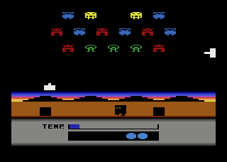
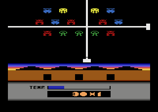
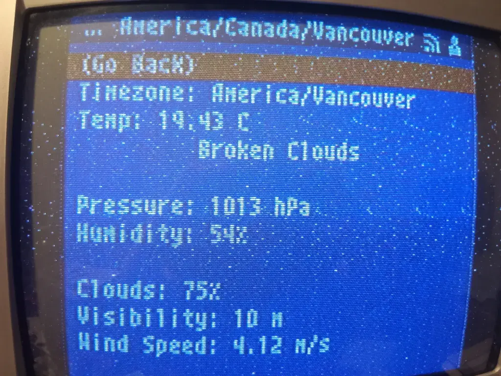
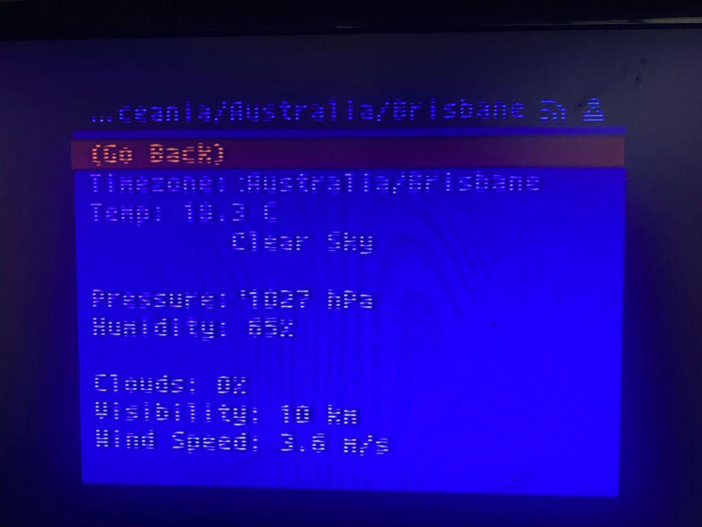
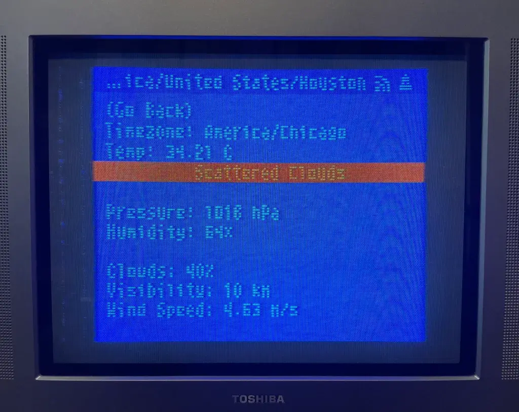
Current weather on #Atari2600 console with PlusCart(+) https://forums.atariage.com/topic/297172-pluscart-an-inexpensive-diy-wifi-multicart/page/53/#findComment-5678210 #atari #retrocomputing
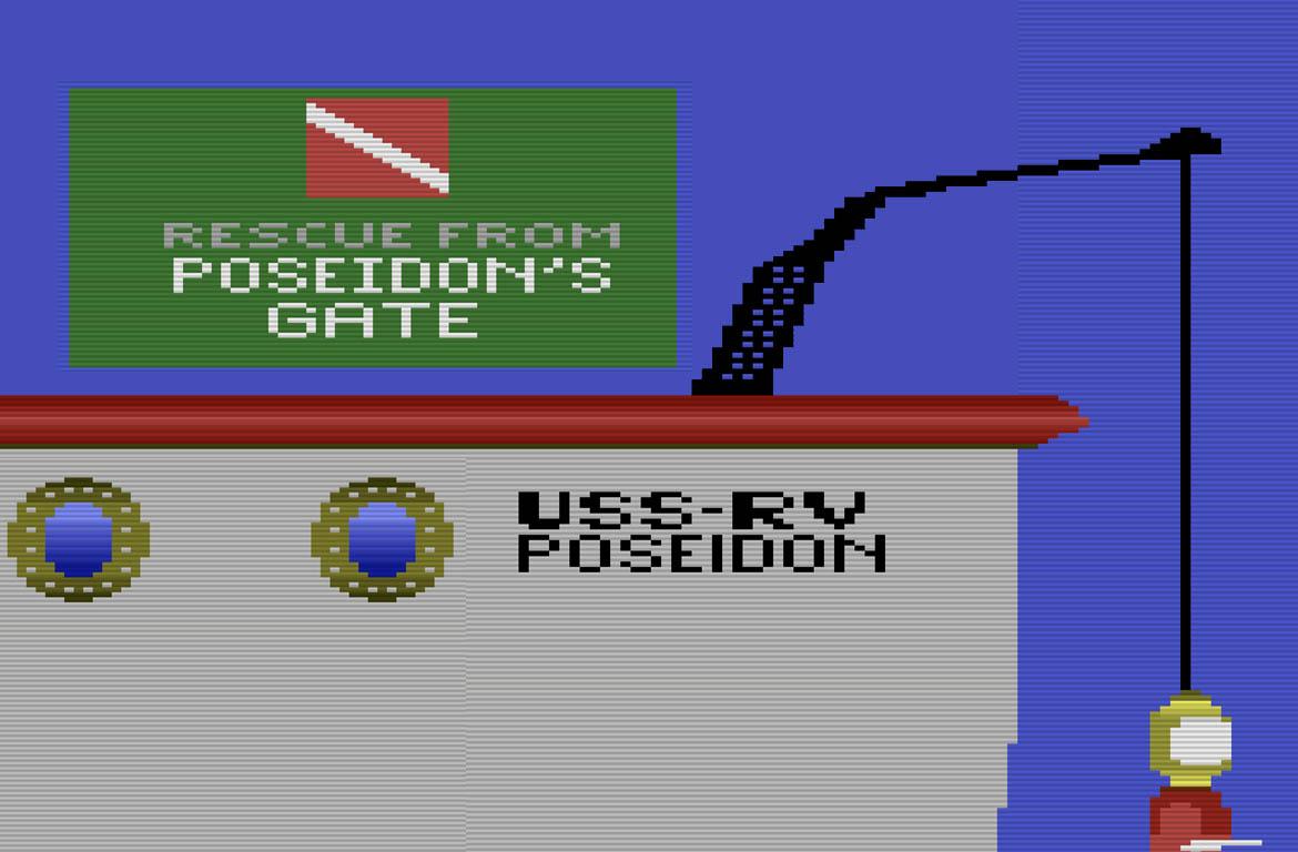
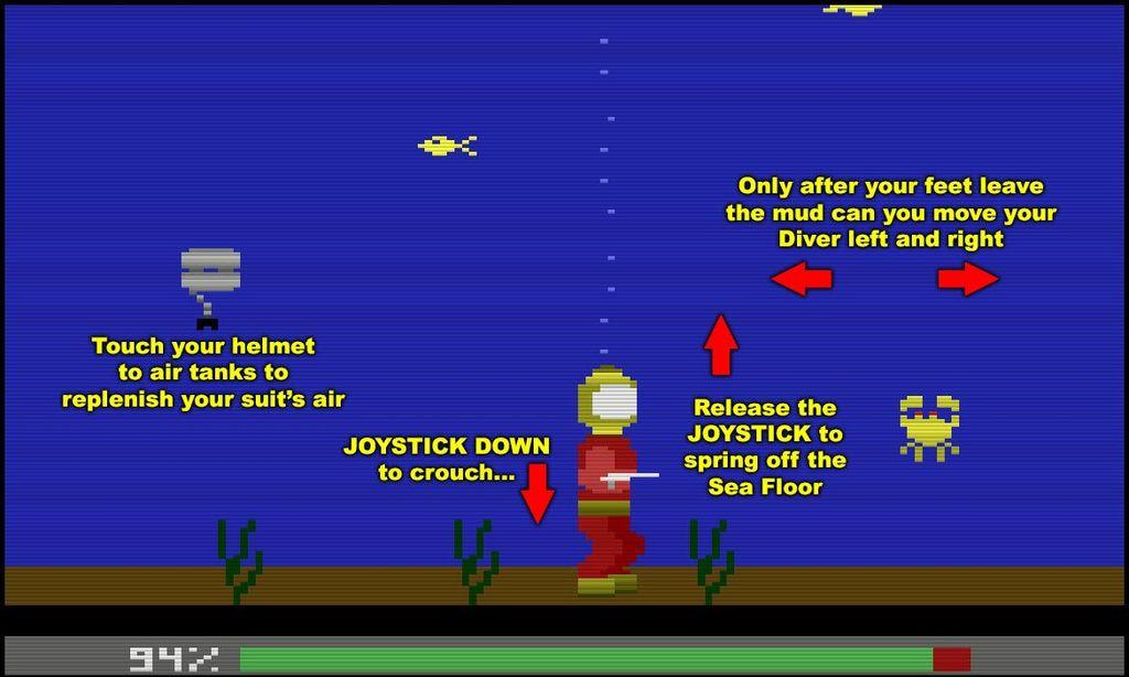
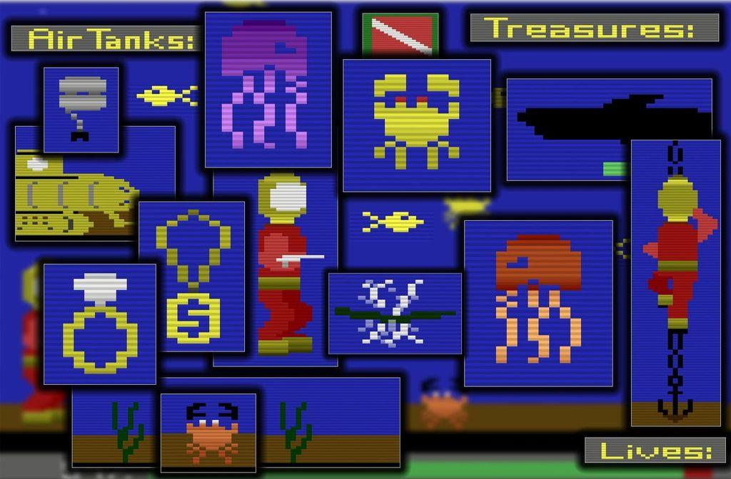
Audacity Games pages dedicated to David Crane's upcoming game for #Atari2600 console, Rescue from Poseidon's Gate, are now live so we can find out more about it. https://adgm.us/portal/guide03.html #atari #retrogames

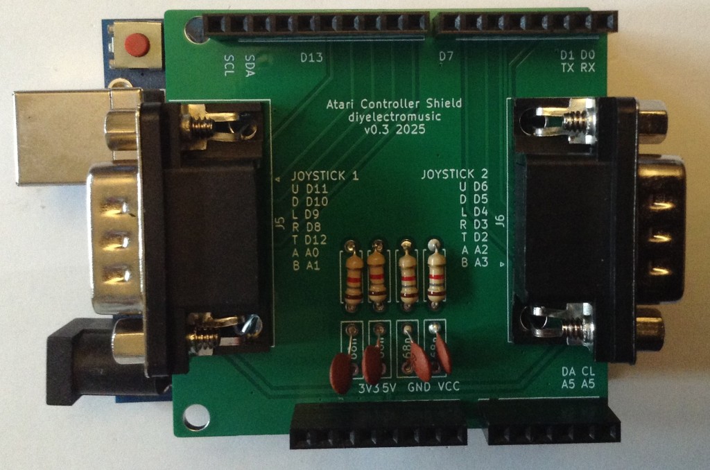
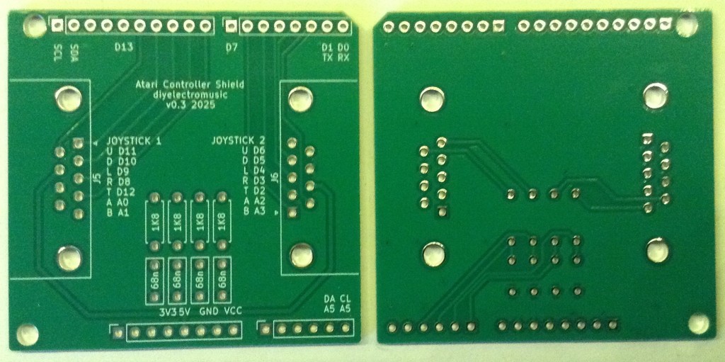
Atari 2600 Controller Shield PCB Revisited – Part 3
Following on from Atari 2600 Controller Shield PCB Revisited – Part 2 someone on Mastodon made the point that the reason they tended to use RC circuits to read paddles “back in the day” was due to the expense of ADCs.
Which triggered a bit of an “oh yeah” moment.
The whole point was not to worry about the analog levels at all, and just measure the time it takes for the pin to read HIGH again.
So this looks back at removing the whole ADC thing with a simple “if (digitalRead(pin))” condition!
Warning! I strongly recommend using old or second hand equipment for your experiments. I am not responsible for any damage to expensive instruments!
If you are new to Arduino, see the Getting Started pages.
The Code
The overarching principles are the same as for Atari 2600 Controller Shield PCB Revisited – Part 2 but instead of all the bespoke code to read the analog to digital converter, I’m relying on the following:
- A digital input pin has a threshold for which the input is considered HIGH.
- We can wait for the input reading to register as HIGH instead of looking for absolute thresholds of an analog value.
- For an ATMega328P the threshold is 0.6 x VCC or around 3V. This is equivalent to just over 610 on a 0 to 1023 scale of an equivalent analog reading.
Taking this into account and using largely the same ideas as before, I can reuse most of the code but with the following timing and threshold values instead:
- Start scaling (the 0 point): 10
- End scaling (the 1023 point): 350
The timer TICK is still 100uS and the “breakout” point is still 1000.
When it comes to reading the digital INPUT, I’m using PORT IO once again for speed and expediency.
for (int i=0; i<4; i++) {
  if ((PINC & (1<<i)) == 0) {
    // Still not HIGH yet
  }
}
Here is the complete, now greatly simplified, basic code:
#include <TimerOne.h>

#define RAW_START    10
#define RAW_END     350
#define RAW_BREAK  1000
#define RAW_TICK    100

unsigned padState;
unsigned padCount[4];
unsigned atariValue[4];

void atariAnalogSetup() {
  Timer1.initialize(RAW_TICK);
  Timer1.attachInterrupt(atariAnalogScan);
  padState = 0;
}

void atariAnalogScan (void) {
  if (padState == 0) {
    DDRC  = DDRC | 0x0F;     // A0-A3 set to OUTPUT
    PORTC = PORTC & ~(0x0F); // A0-A3 set to LOW (0)
    padState++;
  } else if (padState == 1) {
    DDRC  = DDRC & ~(0x0F);  // A0-A3 set to INPUT
    for (int i=0; i<4; i++) {
      padCount[i] = 0;
    }
    padState++;
  } else if (padState > RAW_BREAK) {
    for (int i=0; i<4; i++) {
      atariValue[i] = 1023 - map(constrain(padCount[i],RAW_START,RAW_END),RAW_START,RAW_END,0,1023);
    }
    padState = 0;
  } else {
    for (int i=0; i<4; i++) {
      if ((PINC & (1<<i)) == 0) {
        padCount[i]++;
      }
    }
    padState++;
  }
}

int atariAnalogRead (int pin) {
  return atariValue[pin-A0];
}

void setup() {
  Serial.begin(9600);
  atariAnalogSetup();
}

void loop() {
  Serial.print(padState);
  Serial.print("\t[ ");
  for (int i=0; i<4; i++) {
    Serial.print(atariAnalogRead(A0+i));
    Serial.print("\t");
    Serial.print(padCount[i]);
    Serial.print("\t][ ");
  }
  Serial.print("\n");
}
Closing Thoughts
Sometimes one really can’t see the “wood for the trees” and this was one of those occasions. I was so took up with thinking about how a modern system might think about a problem without thinking about the original reason for the particular solution.
It makes so much more sense thinking about it in these terms now. All it took was an observation from another, namely:
“So I know the RC timer is the classic way to sense analog paddles but they also didn’t have cheap ADCs back then.”
Many thanks “Chip” for that observation 🙂
Kevin
#arduinoUno #atari #atari2600 #include #potentiometer #TICKs
And now I can properly "properly" read all four paddles.
But that was a lot more complicated than I thought it would be. Even by the standards of my previous "that was a lot more complicated" statement!
Maybe I'm just a bit slow with this one! (or getting old) :)
Anyway, I finally have something I'm happy with. Now to actually do something with it!
(the things one does to avoid cracking open some vintage gear and changing it...)
https://diyelectromusic.com/2025/06/22/atari-2600-controller-shield-pcb-revisited-part-2/
Atari 2600 Controller Shield PCB Revisited – Part 2
This has another look at my updated Atari 2600 Controller Shield PCB in order to attempt to read all four paddle controllers a bit more accurately and efficiently.
Update: A much simpler approach is now described in Atari 2600 Controller Shield PCB Revisited – Part 3.
Warning! I strongly recommend using old or second hand equipment for your experiments. I am not responsible for any damage to expensive instruments!
If you are new to Arduino, see the Getting Started pages.
Theory and Design
The previous code (Atari 2600 Controller Shield PCB Revisited) just used analogRead, but set out the basic algorithm required to read the paddles.
To recap, this is what needs to be done:
SET pin to OUTPUT
SET pin to LOW
SET pin to INPUT
Start timer
WAIT WHILE (voltage on the analog INPUT pin is NOT HIGH)
Stop timer
But this has to be done for each of the analog inputs for the paddles, and to do that efficiently means doing it in parallel for each input.
The update algorithm is thus going to be:
Configure a 100uS TICK timer.
On the FIRST TICK:
   Set all analog pins to OUTPUT
   Set all analog pins to LOW
   Set all analog pins to INPUT

On subsequent TICKS:
   Read the analog value for each analog pin
   IF value < threshold THEN
       Increment counter for that pin

On last TICK:
   Convert the counter for each analog pin into a pin "reading"

Keep repeating the sequence
I’m using the TimerOne library to setup my recurring TICK timer. This makes counting the time easier, as with a fixed TICK I just need to count the TICKs themselves.
I’m no longer stopping once the threshold has been reached though, I just stop counting for that pin. The whole sequence is determined by an overall counter which has to be long enough to support the longest reading.
In the end, after lots of experimentation, I’ve gone with the following values:
- Analog read value threshold for “complete”: 900 (out of 1023)
- TICK timer period: 100uS
- Total number of TICKS for each pass through the algorithm: 1000
As part of working through the above, I needed to make a note of the maximum and minimum number of TICKS that I want to correspond to a final 0 or 1023 when converting to an analog value. I used the following (again after a lot of experimentation):
- Start: 10 – to correspond to analog value 0
- End: 900 – to correspond to analog value 1023
To get to the final analog reading from the stored pin counter, I used the Arduino constrain and map functions as follows:
map(constrain(count,START,END),START,END,0,1023);
Actually in order to ensure that “clockwise” increases the value, I actually then subtract the above from 1023 to reverse the sense of the pots.
Efficient Analog Readings
One thing I was very conscious of though, the Arduino analogRead() function is notoriously slow to execute, so as I’m using this up to four times in this timer routine, I need that to be as slick as possible.
I know it is possible to create a “fastAnalogRead” function, as I know the Mozzi library has an implementation. This pokes the registers of the ATMega328 directly, as covered in section 28 of the ATMega328P datasheet.
The main issue is the ADC on an ATMega328 takes a bit of time to actually produce a reading, so the basic process involves starting the conversion; waiting until it says the conversion is complete; then read the value. And this has to be done for each ADC channel one at a time.
I can recommend Tom Almy’s excellent “Far Inside the Arduino” to walk through the details. It is possible to configure a single conversion, which mirrors the Arduino’s analogRead() function; a continuous free-running read, which is fine for a single channel; or an interrupt-driven free-running mode that can work through each channel in sequence.
I’ve used the latter leading to the following functions, which are hard-coded to read A0 to A3 only:
// Direct analog reading taken from
// "Far Inside the Arduino" by Tom Almy.
uint8_t adcIdx;
volatile uint16_t adcVal[4];
void fastAnalogReadStart (void) {
    // Start the analog read continuous process.
    adcIdx = 0;
    DIDR0 |= 0x3F; // Turn off all digital input buffers for A0-A7
    ADMUX = (1<<REFS0);  // Use VCC Reference and set MUX=0
    ADCSRA = (1<<ADEN) | (1<<ADSC) | (1<<ADIE) | 7; // Start with interrupts and PreScalar = 7 (125kHz)
}

void fastAnalogReadStop (void) {
  // Stop ADC, stop interrupts, turn everything off
  ADCSRA = 0;
}

uint16_t fastAnalogRead (int adc) {
  if (adc >= 4)
    return 0;

  uint16_t adcvalue;
  cli(); // disable interrupts
  adcvalue = adcVal[adc];
  sei(); // reenable interrupts
  return adcvalue;
}

// ADC reading interrupt routing
ISR(ADC_vect) {
  digitalWrite(T_ADC, HIGH);
  uint16_t last = adcVal[adcIdx];
  adcVal[adcIdx] = ADCW;
  // Move onto next MUX
  adcIdx = (adcIdx+1) % 4;
  ADMUX = (1<<REFS0) + adcIdx;
  // Start new conversion
  ADCSRA |= (1<<ADSC);
  digitalWrite(T_ADC, LOW);
}
Curiously, this apparently takes around 104us per analog read, so I need to leave a bit of time when I first enable the analog process for the first few readings to appear. I do this by skipping a few TICKs prior to starting the main logic of the reading and counting process.
The counting process calls fastAnalogReadStart() and fastAnalogReadStop() to control the otherwise asynchronous running of the analog process alongside the timer process.
Efficient Digital Processing
In a similar manner, using pinMode and digitalWrite for each of the analog pins at the start of the process can be quite slow for a timer-driven interrupt routine too. So I’ve used PORT IO directly to drive all four analog pins as follows:
    DDRC  = DDRC | 0x0F;     // A0-A3 set to OUTPUT
    PORTC = PORTC & ~(0x0F); // A0-A3 set to LOW (0)
// wait for a TICK then
    DDRC  = DDRC & ~(0x0F);  // A0-A3 set to INPUT
All analog pins are on PORTC and so can be handled directly as shown above. This is, once again, hard-coded to work with A0 to A3 only.
The Code
Wrapping all this up gives a usable way to read the Atari paddle controllers. Note that there are two parallel 100uS interrupts going on continuously for this to work.
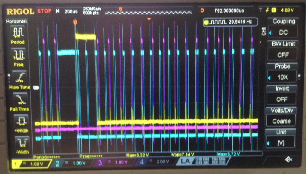
The final test code I’ve produced adds in four digital outputs to allow measuring the following:
- The start-up phase of the counting process (yellow).
- The timer routine (blue).
- The ADC routine (purple).
- The final loop.
The colours refer to the following scope display, which shows the counter start-up and subsequent timer and ADC routines kicking in.
We can clearly see the ADC processing stopping prior to the start (the trigger point and yellow HIGH trace), as well as the timer routine taking a lot longer at this point. Presumably this is running four of the map/constrain operations on the counter readings to turn them into analog readings.
I’m fine with that, that seems to work fine for me.
It is also possible to see how the ADC interrupt is running a fraction slower than the timer interrupt. If the former is 104uS and the latter 100uS that would be about right I’d say.
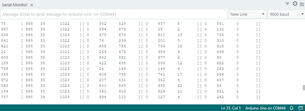
The main Arduino loop simply prints out various values sampled (at “loop speed”) from the processing as it happens.
The fields are ordered as follows:
count [alg1 count1 raw1] [2] [3] [4]
Where:
- count = global counter
- algN = final calculated analog value from pin N
- countN = snapshot of the counter value for pin N
- rawN = raw analog value being read for pin N
Here is a sample output:
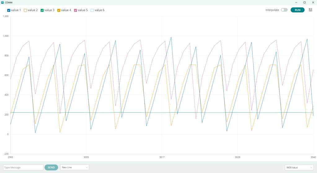
If the readings are limited to a single channel, rather than all four, then it makes quite a good set of readings for the Arduino Serial plotter as follows:
It’s not perfect, but it gives a pretty good idea what is going on – especially when watched live as the controller is changed.
The top (purple, value 5) line is the sampled actual raw analog value for the pin, so we can see the capacitor charging up fairly clearly.
The blue (value 1) line is the global TICK counter counting between 0 and 1000.
The yellow (value 4) line is the pin’s individual counter and we can see where it “caps out” near the top and stops counting as the raw analog value reaches the threshold I’ve set.
The final green (value 3) line is the calculated pseudo analog value (0 to 1023) that corresponds to the above. This is essentially flat as I’m not turning the controller at this point.
The above are all samples taking at “Arduino loop” speed, which is slowed down by the serial printing, but it gives a pretty good idea of what is going on.
As this is a bit more complicated, I’ve put the whole code up on GitHub here: https://github.com/diyelectromusic/sdemp/tree/main/src/SDEMP/ArduinoAtariPaddleScan
Closing Thoughts
This has taken me a very long time to get to this point and there has been quite a bit of head-scratching and experimenting with different values. I tried various thresholds, timer periods (thinking faster would give greater resolution), and various min/max values.
The above are what seem to work best for me and give me the best coverage of the whole range of the controller. Some seemed more accurate but restricted the usable range of the pot for example.
But I think I can actually work with the above now in a fairly usable manner.
Kevin

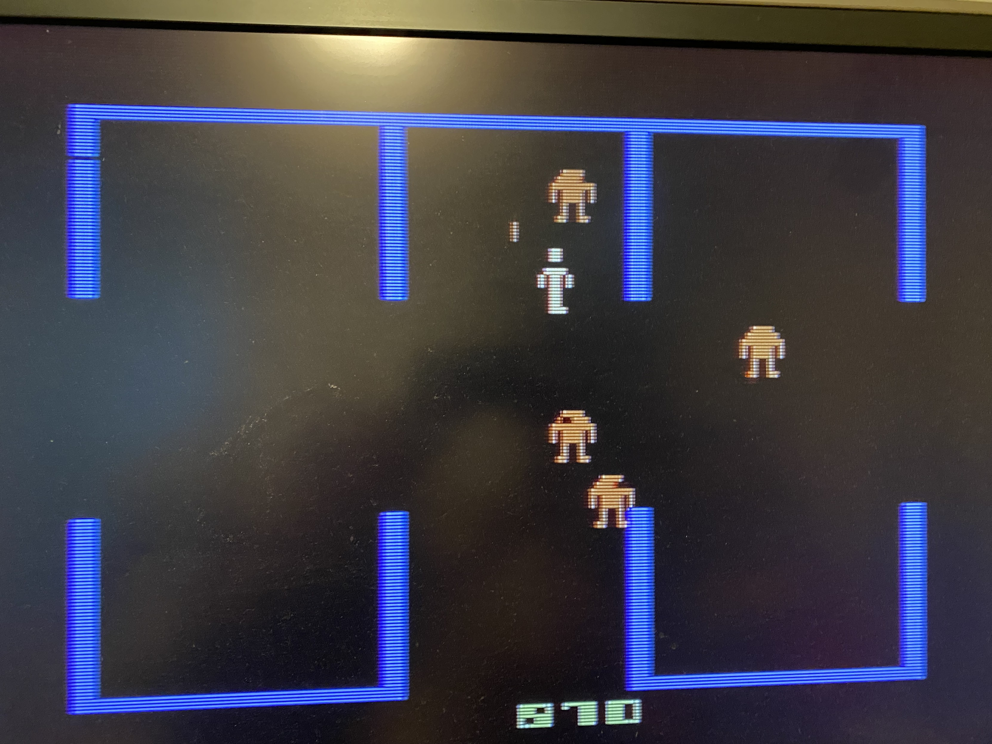
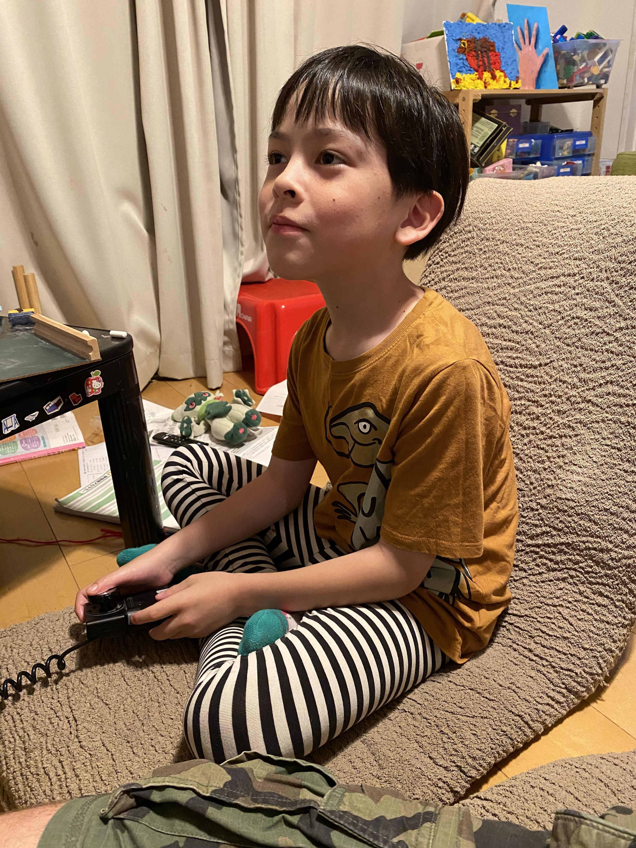
My son is already pretty diehard into #videogames. He asked what are the oldest games I have to play on real consoles. (He knows about PC emulation) So that leaves the #AtariVCS. He really likes #Bezerk which in my opinion is really good taste. I loved that game as a kid too and still do. #Atari2600 #retrogaming
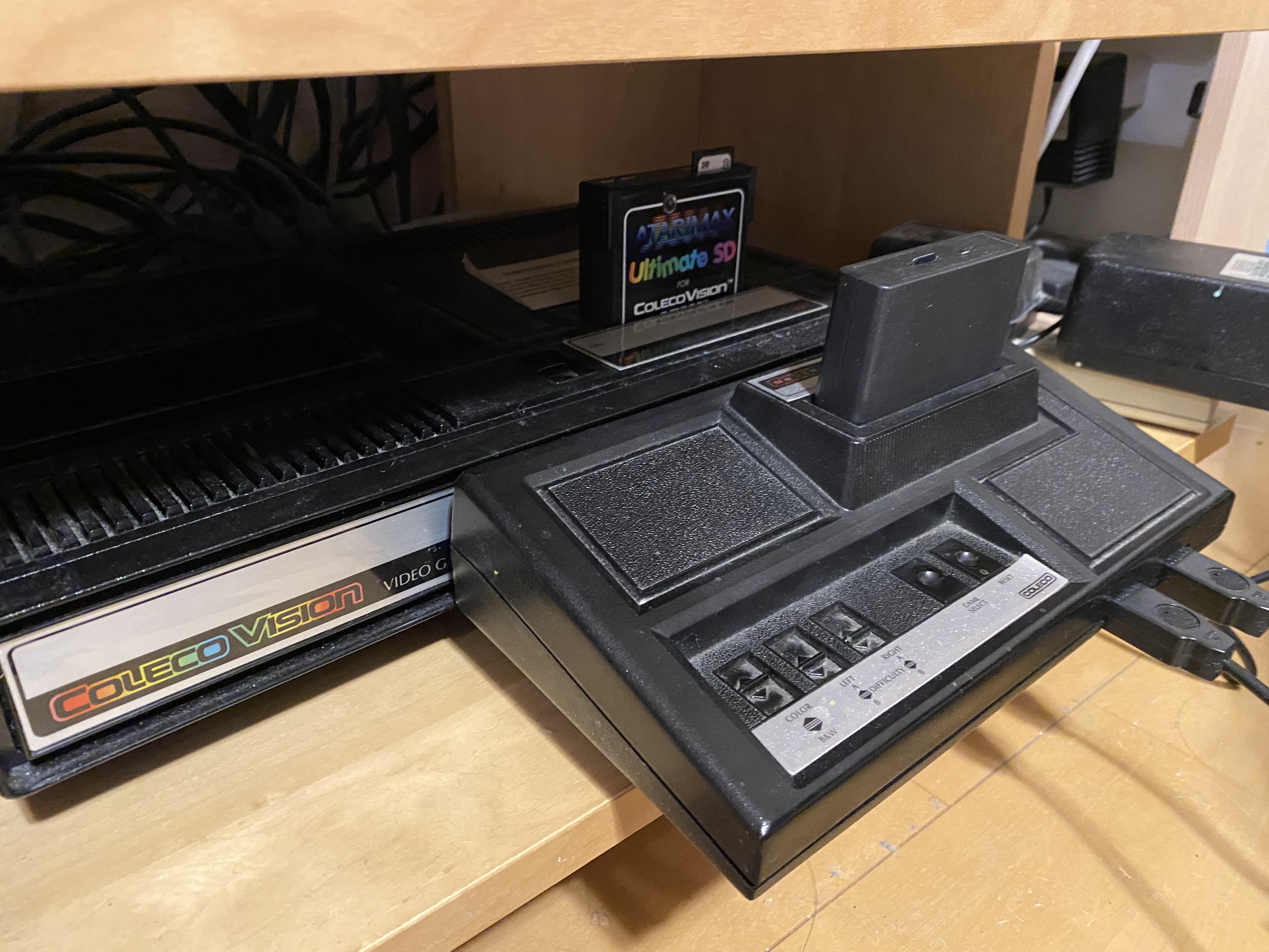
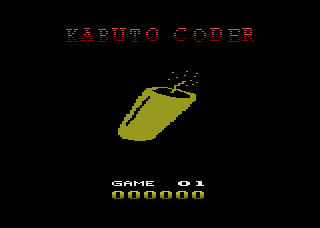
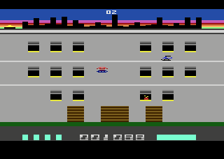
Umi Bombs, new game for #Atari2600 console https://kabutocoder.itch.io/umibombs If you complete the game, you'll get a free key for the PC game Kikaiju Attack. #atari #retrogames


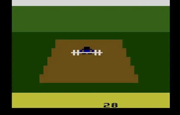
World Weightlifting Championships, work in progress game for #Atari2600 console https://forums.atariage.com/topic/382526-world-weightlifting-championships/ #atari #retrogames
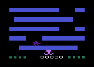
Jumping Jackie, new game for #Atari2600 console https://jumpingjackie.com/ #atari #retrogames


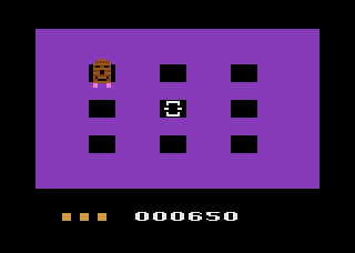
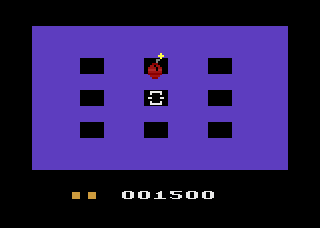
Mole Smash, new free game for #Atari2600 console. Gameplay: https://youtu.be/wLVtwgNCHc0 Info & download: https://www.kiki2600.com/molesmash.html #atari #retrogames


In the floppy disks of the late Jerome Domurat also found an alternate titlescreen made by Mimi Nyden for the #Atari2600 game Swordquest https://forums.atariage.com/topic/382501-alternate-swordquest-title-logo/ #atari #retrogames

Finally. I have a way to "properly" read unmodified Atari paddle controllers from an Arduino.
That was a lot more complicated than I expected it to be.
And arguably it still isn't finished as the code needs optimising to read all four paddles in a useful way that doesn't lock out everything else!
It would be a /lot/ simpler to hack the controllers and just wire the pots across 5V and GND...
https://diyelectromusic.com/2025/06/16/atari-2600-controller-shield-pcb-revisited/

Atari History, Teil 1 – Die Einführung des Atari VCS in Deutschland
Der Mythos Atari. Unzählige Artikel haben Autoren über dieses Thema bereits verfasst, aber unsere eigene Vergangenheit in Deutschland ist dabei kaum berücksichtigt worden. Klaus Ollmann, Geschäftsführer in den Jahren 1980 bis 1984, berichtet in den nun folgenden Zeilen persönlich über die Einführung der Atari VCS-Spielkonsole.
https://www.videospielgeschichten.de/die-einfuehrung-des-atari-vcs-in-deutschland/
#1979 #2600 #Atari #Atari2600 #AtariHistoryReihe #Deutschland #Einführung #Fairchild #GOVI #Hamburg #HeavySixer #Holzleistenimitation #Joysticks #KlausOllmann #Outlaw #Philips #Shootout #SiggiLoch #SpaceInvaders #Sunnyvale #TonyBruehl #VCS #WEA

Atari History, Teil 2 – Die ersten Schritte in Deutschland
Inzwischen sind über 30 Jahre vergangen, seitdem das Atari VCS, die Spielkonsole mit der legendären Holzfront, auch unseren heimischen Markt eroberte. Nicht ganz unbeteiligt an dieser „Invasion der Videospiele“ war Klaus Ollmann, ehemaliger Geschäftsführer von Atari Deutschland.
https://www.videospielgeschichten.de/atari-erobert-deutschland/
#1981 #2600 #AntonBruehl #Arndtstrasse #Atari #Atari2600 #AtariUserClub #AtariHistoryReihe #Bebelallee #CES #ConsumerElectronicsShow #Deutschland #GuidoFrank #Hamburg #HansHermannPein #HansUeliHasler #KlausOllmann #MannyGerard #MarktIntern #MichaelSchanze #Outlaw #Pele #PhilipsG7000 #RayKassar #RenateKnüfer #RolfRehfeldt #SabaFairchild #Shootout #SiggiLoch #VCS #VideoMarkt #WolfgangBlödorn

Atari History, Teil 3 – Erinnerungen von Klaus Ollmann
Bereits zum dritten Mal können wir euch mit der freundlichen Unterstützung von Klaus Ollmann neue Geschichten und Anekdoten aus der guten alten Atari-Zeit präsentieren.
https://www.videospielgeschichten.de/erinnerungen-von-klaus-ollmann/
#1982 #1984 #Activision #AlanAlda #Atari2600 #Atari400 #Atari5200 #AtariHistoryReihe #Battlezone #BluesBrothers #CES #CHIP #ClaudeNobsGründerDesMontreuxJazzFestivals_ #Commodore64 #ElkeLeibinger #FranzBeckenbauer #FürstinGraciaPatriciaVonMonacoGraceKelly_ #GuidoFrank #GüntherNetzer #Hamburg #HartmutHuff #Homecomputer #Imagic #JackTramiel #JohnLandis #MarioAndretti #Mindlink #Pele #PhilipsG7000 #Raubkopien #RayKassar #RenateKnüfer #SnoopyAndTheRedBaron #SpaceInvaders #StevenSpielberg #Superman #Tempest #VideoMarkt #Warlords
Atari 2600 Controller Shield PCB Revisited
As previously mentioned in my Atari 2600 Controller Shield PCB Build Guide the PCB doesn’t work so well with paddle controllers due to the way they are wired up.
This is an update to the PCB to allow the paddles to be used in a very similar way to the original Atari 2600.
Warning! I strongly recommend using old or second hand equipment for your experiments. I am not responsible for any damage to expensive instruments!
If you are new to Arduino, see the Getting Started pages.
PCB Update
This is basically the PCB design as described here: Atari 2600 Controller Shield PCB Design but with the addition of a resistor and capacitor in the paddle circuit as shown below.
These are the values used in the original Atari circuit as can be found in the following references:
- Atari 2600 main circuit: https://atariage.com/2600/archives/schematics/Schematic_2600_Low.html
- Atari 2600 paddle circuit: https://atariage.com/2600/archives/schematics/Schematic_2600_Accessories_Low.html
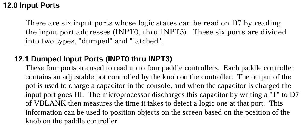
- Details of programming for paddles: “Stella Programmer’s Guide” section 12.1, TIA section 8B, Figure 8.
These also describe the operation of the TIA and paddle INPUT circuit:
The block diagram for the TIA shows the transistors mentioned, that are controlled by D7 in VBLANK.
The basic idea being described is that setting D7 turns on the transistors that will drop the voltage from the capacitor to zero. Then the capacitor will charge again and the time it takes to charge depends on the position of the paddle, which is connected to a 1M variable resistor. By measuring the time it takes to charge the capacitor back up, the position of the paddle can be determined.
From all this, we can conclude that the required approach for an Arduino should be as follows (assuming the paddles are connected to analog INPUT ports):
SET pin to OUTPUT
SET pin to LOW
SET pin to INPUT
Start timer
WAIT WHILE (voltage on the analog INPUT pin is NOT HIGH)
Stop timer
This works because the ATmega328P’s analog input ports (at least A0 to A5) can also be used as digital input and output ports.
Note: the Arduino reference documentation states that if swapping from digital output to analog input, then the mode should be explicitly set prior to any calls to analogRead (see “caveats” here).
Build Steps
Solder the components in the following order:
- Resistors
- Capacitors
- Arduino headers
- 9-way D-type connectors
Testing
I recommend performing the general tests described here: PCBs.
The following sketch will read the value of one of the paddle controllers, implementing the algorithm described above.
#define PAD_PIN A0

#define RAW_MAX    950
#define RAW_SHIFT  7
#define RAW_OFFSET 3
#define RAW_BREAK  150000

unsigned long atariRawAnalogRead (int pin) {
  unsigned long start = micros();
  pinMode(pin, OUTPUT);
  digitalWrite(pin, LOW);
  pinMode(pin, INPUT);
  while ((analogRead(pin)<RAW_MAX) && (micros()<(start+RAW_BREAK)))
   {}
  return (micros() - start);
}

int atariAnalogRead (int pin) {
  unsigned long val = atariRawAnalogRead(pin) >> RAW_SHIFT;
  if (val < RAW_OFFSET) {
    return 1023;
  } else if (val < 1023+RAW_OFFSET) {
    return 1023-(val-RAW_OFFSET);
  } else {
    return 0;
  }
}

void setup() {
  Serial.begin(9600);
}

void loop() {
  Serial.print(atariRawAnalogRead(PAD_PIN));
  Serial.print("\t");
  Serial.print(atariAnalogRead(PAD_PIN));
  Serial.print("\t");
  Serial.println(analogRead(PAD_PIN));
}
The configuration values at the top are determined through a bit of trial-and-error, noting the following:
- A single reading could take up to 150 mS.
- The maximum analog reading corresponds to a voltage of around 4.6V, which is around 940 out of 1023.
- Timing the charging using microseconds gives more resolution, especially at the quicker end.
- Shifting the measurement >>7 turns the up to 150,000 value into a value of up to 1170.
- The residual readings are largely in the range 3 to 1170 now, so a subtraction is required to drop that down to 0, and the top reading needs capping at 1023 to match that returned by analogRead().
- Reversing the sense of the readings means that clockwise reads higher than anticlockwise.
- Note: if not controller is plugged in, then the while loop would never complete, so a breakout timer value is provided set to the expected maximum of around 150mS.
The Arduino functions are relatively slow compared to direct register access, but as the time out involved is up to 150mS, I’m not too worried about trying to speed up the Arduino calls.
If I was attempting to read all four paddle controllers at the same time, some optimisation would be required. It might even be worth attempting to read them using a timer interrupt and a sampling routine.
- Update: This has been described here: Atari 2600 Controller Shield PCB Revisited – Part 2
If this was to be used properly, some averaging of values would also be required.
Other PCB Notes
- This PCB still works fine with keypad controllers. The additional resistor and capacitor does not affect the keypad scanning function.
- This PCB also still works fine with joysticks, as the digital lines have not be altered.
- It is possible to use this PCB with the “additional resistor” method described in Atari 2600 Controller Shield PCB Build Guide. This requires installing a resistor where the capacitor is meant to go and shorting the existing resistor link together.
Find the updated PCB on GitHub here.
Closing Thoughts
There are now several approaches that can be used to read Atari paddle controllers from an Arduino.
- Doctor the wiring of the paddles themselves to internally connect the potentiometer to the 5V and GND line, then connect it directly to an Arduino analog input like any other potentiometer.
- Use the approach described in Atari 2600 Controller Shield PCB Build Guide to add a resistor and make a variable potential divider, adjusting the read values in software.
- Use the approach described above to time the charging of a capacitor, mirroring how the original Atari circuit and TIA would have worked.
Kevin

Atari History, Teil 5 – Drei Tage mit Pelé in Hamburg
Es ist der 4. Mai 1981. An einem grauen und kalten Montagmorgen, typisches Wetter für diese Jahreszeit, versammelten sich zahlreiche Besucher am Hamburger Flughafen und beobachten aufmerksam die ankommenden Passagiere.
https://www.videospielgeschichten.de/drei-tage-mit-pele/
#1981 #2600 #Alster #Alsterhaus #Atari #Atari2600 #AtariClubMagazin #AtariNiederlassung #AtariHistoryReihe #Brinkmann #ClubMagazin #FIFA #FranzBeckenbauer #Fussball #Hamburg #HotelIntercontinental #HSV #KlausOllmann #Pele #Soccer #Sportspiel #SteveWright #VCS
Client Info
Server: https://mastodon.social
Version: 2025.04
Repository: https://github.com/cyevgeniy/lmst