this was a really cool project for the Atari 2600 that i remember from the 2010s
it allows you to make games for the 2600 much, much faster than learning how to code in assembly language
this was a really cool project for the Atari 2600 that i remember from the 2010s
it allows you to make games for the 2600 much, much faster than learning how to code in assembly language
The Horrible Ghosts of Uranus, Pac-Line clone for #Atari2600 console coded with batariBasic in 2KB https://forums.atariage.com/topic/387774-the-horrible-ghosts-of-uranus/#findComment-5786907 #atari


Not our consoles collection: bcoz our shelf will only contain COMMODORE 64/128 and AMIGA equipment 🤣
#Console #Sega #Nintendo #Sony #Playstation #GameCube #Switch #XBOX #Xbox360 #Microsoft #PS1 #PS3 #PS4 #N64 #3DO #Atari #Jaguar #MegaDrive #Atari2600

As Criaturas, new Brazilian game for #Atari2600 console https://forums.atariage.com/topic/387635-as-criaturas-atari-jogo-brasileiro-brazil/


The coder of the game Oh Shoot! for #Atari2600 console made 100 alternate versions with different sprites https://forums.atariage.com/blogs/entry/19714-oh-shoot-got-hacked-merry-christmas/ #atari


One secret agent. One very busy elevator car. A lot of secrets. And a lot of enemies to take down while you're going down. An arcade classic gets a long-overdue pitch-perfect remake on the #atari2600, and it's heading straight for the Phosphor Dot Fossils floor. #retrogaming https://www.youtube.com/watch?v=q-9x4ScOsgQ

Harry Peril, Ricky Dangerous inspired work in progress game for #Atari2600 console https://forums.atariage.com/topic/387640-new-game-wip-harry-peril-rick-dangerous-clone/ #atari


CrazyNoid, new game for #Atari2600 console https://forums.atariage.com/topic/387642-crazynoid/ #atari


Transformers, work in progress game for #Atari2600 console https://forums.atariage.com/topic/387602-transformers-2600-homebrew/ #atari


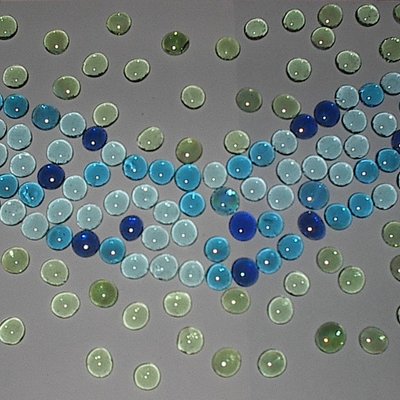
Shift arriva su C64, Amiga, Atari e ZX Spectrum: il puzzle in bianco e nero che sfida la percezione
https://www.bitchronicles.net/2026/01/shift-arriva-su-c64-amiga-atari-e-zx.html
@giochi


Using a #OneROM as a 2732 EPROM replacement in an #Atari2600 cartridge.
https://emalliab.wordpress.com/2026/01/22/atari-2600-cartridge-emulation-part-4/
Atari 2600 Cartridge Emulation – Part 4
In Part 3 I finished by noting that I’d sent off some OneROM boards to be made. This posts looks at what happened when I got them back.
OneROM is a replacement for 24-pin or 28-pin (EP)ROMs used in much vintage hardware, designed by ‘piers rocks’. There are two versions of each type, one based on an STM32 and one on an RP2350.
There is a lot of documentation available and a suite of tools that is growing in ease of use almost daily.
Key links:
Manufacturing
To give you an idea of the speed of development, when I sent off the recommended design for the “Fire” (RP2350) 24-pin variant the recommended version was fire-24-c – i.e. revision C of the PCB. By the time I had the boards back, the recommended version was fire-24-d.
Massive credit to piers.rocks with the fabrication instructions. These boards have been designed for the cheapest, practical default options for manufacturing. The full process is described in full here: https://github.com/piersfinlayson/one-rom/tree/main/sdrr-pcb
Everything went pretty smoothly for me. I had to upload the Gerbers, BOM and positioning files from the “fab” area of the PCB revision in question. The one issue was that one of the capacitors wasn’t available, but there was an equivalent that had wide availability and the same properties as far as I could see, so I used that.
The cost was a little more than initially implied by the information I’d read but that is mostly because it doesn’t talk about postage, which naturally will be different for everyone. In the end the “all in” cost (postage and all) was around £8 per device for me.
First Install
Having received these back, there are a few options for getting them up and running:
There are a number of default ROM configurations that can just be selected and run, but I’m going to try to get an Atari 2600 game ROM onto a OneROM emulating a 2732.
Unfortunately I hit a few issues straight away:
What I did find, was that my boards started up in the RP2350 BOOT mode, so I got a drive appear ready to accept a UF2 file. But OneROM does not provide UF2 files.
It is apparently possible to install one of the firmware files (the onerom-fire-24-c*.bin files from the Releases area) using picoflash over USB, which I was able to do. But there is no default firmware for a 2732 and no means to get my Atari ROM built.
As I say though, asking on the discussion forums, by the time I got back to seeing if I had any reply, piers.rocks had updated the web tool to support building a custom ROM, which I subsequently went on to do.
Unfortunately I seem to have an issue now with my 4K ROM appearing as a repeating 2K ROM with only the first half present. After a bit of too-ing and fro-ing on the forums, it turns out this was a bug in the 2732 support. Once again, it was diagnosed and fixed withing 24 hours of having the conversation. There is a detailed analysis of the issue and solution in the bug report here: https://github.com/piersfinlayson/one-rom/issues/103
Build from Scratch
As part of attempting to get a firmware image containing my ROM, I went through the installation instructions to get a dev environment up and running. I was able to make some notes and sent them off, and again they were all included into some updated documentation within 24 hours.
The main information required is here: https://github.com/piersfinlayson/one-rom/blob/main/INSTALL.md
And it now includes full instructions on how to get everything built too.
For my ROM, I copied the ROM file into my build area and then had to create a configuration file for the build:
one-rom/config/a2600.mk
ROM_CONFIGS = \
file=spaceinv.bin,type=2732
Then use the make command detailing my board, revision, configuration to use and location of the toolchain:
~/src/one-rom$ MCU=rp2350 HW_REV=fire-24-c CONFIG=config/a2600.mk TOOLCHAIN=/usr/bin/ make
This leaves me with a firmware file in sdrr/build that I can now use with the Studio tool to load onto the OneROM.
At this point I can check it in an EPROM programmer if required (as per instructions in this video though, there are some caveats – do not use “Detect pins” or “Check ID” or equivalent operations – these often involve using higher voltages on the pins of real devices which will damage OneROM) and I can see the whole ROM is now intact.
At this point I can now put it into the custom cart as described in Part 3 – noting the small white arrow indicating pin 1 (opposite end to the USB socket).
And lo and behold – it works 🙂
My version of Fire has two “bank select” jumpers so it should be possible to allow selection between up to four different ROMs (00, 01, 10, 11). Another option is to use the 28-pin version in place of the 27C512 used in the multi-cart described in Part 3.
A Note on Bank Select
One difference between my version, fire-24-c, and the latest release, fire-24-d is that the number of bank select pins was returned to 4. It was reduced to 2 in rev C to ease routing of the SWDIO and SWCLK pins to the header, so I was curious as to how this all worked, so I had a brief diversion into the code.
The summary, is that there is a firmware configuration that is generated in the management tools (via json or other configuration files) that ends up getting linked into a specific address in the firmware. This is the “sdrr_info” structure which is positioned according to: https://github.com/piersfinlayson/one-rom/blob/main/sdrr/link/flash_sdrr_info.ld. The key types that result are sdrr_info_t and sdrr_info_t (among others).
Within this structure are the details of how to read the bank select pins. They get stored in the following within the code:
The function setup_sel_pins() in rp235x.c works through the configuration and does things like:
The bit mask can then be used with the function setup_sel_pins() to read the values of the select pins and use it to select which ROM to use in a multi-ROM configuration.
The actual configuration for the rev C and D boards select pins are shown below.
rust/config/json:

fire-24-c.json:                       fire-24-d.json:
"sel": [                              "sel": [
  26,                                    25,
  27                                     24,
],                                       26,
"sel_jumper_pull": [0, 0],               27
                                      ],
                                      "sel_jumper_pull": [0, 0, 0, 1],
                                      "swclk_sel": 26,
                                      "swdio_sel": 27,
This reflects the different layout/connection between the two revisions.
The upshot of all this is that whilst SWDIO/SWCLK and SEL_C/D are overlapped on Rev D, I’m pretty sure I can’t use the same pins on my Rev C board. I think I’m stuck with just two bank select pins.
Here are some other design notes (correct as of Jan 26, but as I say the documentation is continually being updated) that I thought was really interesting relating to ROM banks. From: https://github.com/piersfinlayson/one-rom/blob/main/docs/TECHNICAL-DETAILS.md
“The selected ROM image is pre-copied to RAM on boot, so the data is loaded very quickly based on the address pin state.”
“Each ROM image is stored in a separate 16KB chunk of data on the flash. This is true for all ROM types, even though they only take up 8KB, 4KB or 2KB of space. This is done to make the main loop faster, so it can access to the ROM image using the chip select line states as part of the address offset into the ROM image.”
“The ROM images are stored in flash in a “mangled” fashion – that is, to avoid having to remap the address lines and data lines in software when the ROM is being queried (as the PCB layout does not assign address and data lines to the equivalent STM32F4 GPIOs). Therefore, if you look at the ROM images on the flash, they will appear very different to the original files you supplied.”
I read that last part as reordering the ROM data in a sequence that is already optimised for the address line mapping in the microcontroller. Whilst that must be quite complex to do (and debug) that is a pretty neat solution. There are loads more details in the heavily commented rom_asm.h and rom_impl.c files (for the STM32 version) and piodma/piorom.c (RP2350) in the sdrr/src.
From: https://github.com/piersfinlayson/one-rom/blob/main/docs/TECHNICAL-SUMMARY.md
“One ROM pre-processes the ROM images during the build process to match the exact GPIO pin mapping. Therefore PC0 is actually used as address line 0 looking up in the ROM image, but the data bytes in the ROM have been reordered so the correct byte is retrieved. The bits within the data byte are also reordered, so that the real bit 7 is actually at the bit 0 location, etc.”
“This is all done during the build process to avoid either the startup code, or, worse, the main loop, from having to do any bit manipulation at runtime – keeping everything as fast as possible.”
“All ROM images are stored as 16KB blocks in flash, regardless of actual size. This is because, in additional to the address lines being re-mapped, the chip select lines are also embedded within the address line port on the STM32F4.”
“This means that 14 bits (A0-12, plus one CS line) = 16KB of address space needs to be looked up to find the correct ROM image. It also means that, as we look up the data byte using the output of the address port, the chip select line(s) can either be 0 or 1 when we read the address lines. This means that we have to store duplicates of the ROM images – 2x the images for a 2364, 4x for a 2332, and 8x for a 2316. Hence the need for 16KB blocks.”
“Again, the pre-processing into 16KB blocks is done during the build process.”
This is a great example of optimisation and pre-calculating everything possible to get the optimum response from the choice of microcontroller.
And reading through the design notes and reasoning is a really interesting insight.
Conclusion
Getting this going has been a really positive experience:
The only downside is the amount of stuff that has to be set up to build everything.
Now I just have to work out what it is about Studio install that my Windows installation doesn’t like, but as the web tool is constantly developed, the need for Studio is decreasing and when I need the more complete tool, I’m probably already in my Linux VM anyway.
Also, I’ve only just scratched the surface of what is possible. I’ve just read, for example, that there are some configurations where several ROMs from a vintage machine can be replaced with a single OneROM as long as the various chip select/enable pins are wired up appropriately, and the OneROM has all the required ROM images installed.
A massive thank you to piers.rocks for creating this, documenting it so well, releasing it as open source, and responding so quickly and positively to my questions. If this fits a use you have, I can recommend giving it a go.
Kevin


The Way of the Exploding Fist on #Atari2600 console? No, but nice proof of concept https://youtu.be/HYYz8gA7HN0 #atari

Sailboat Journey, new game for #Atari2600 console https://grodines.itch.io/sailboat-journey #atari


#MissileCommand #Arcade is a great hack of the #Atari2600 game 👍
You control the crosshair with a joystick in left port and your missile bases with the 3 buttons of a Track & Field controller in right port 🕹
You can use a Trakball but only in joystick mode 🤗
That all looks very avantgarde but the highest score I did with a Dualsense in #twinstick mode via #Unijoysticle2 #Amiga and two #Mega7800.
The hacked rom was put in uf2 format on an #OtakuFlash 😎


Archery Duel, new two players game for #Atari2600 console https://grodines.itch.io/archery-duel #atari


New release of Break Invade!, work in progress game for #Atari2600 console. Interesting mix of Pong, Breakout and Space Invaders https://forums.atariage.com/topic/369345-break-invade-game-for-atari-2600-in-development/#findComment-5780686 #atari


Rod Hull Replays: Ms Pac-Man - Atari 7800 - First use of Trooper Joystick 🕹️ Lets call it an review!
https://www.youtube.com/watch?v=DPxTSQd_4Vg