My plan for the day is to see if I can turn these components into something that makes noise, following @todbot's CircuitPython synthio tutorials
https://github.com/todbot/CircuitPython_Synthio_Tutorial/tree/main?tab=readme-ov-file
My plan for the day is to see if I can turn these components into something that makes noise, following @todbot's CircuitPython synthio tutorials
https://github.com/todbot/CircuitPython_Synthio_Tutorial/tree/main?tab=readme-ov-file

Pico Touch Board Audio
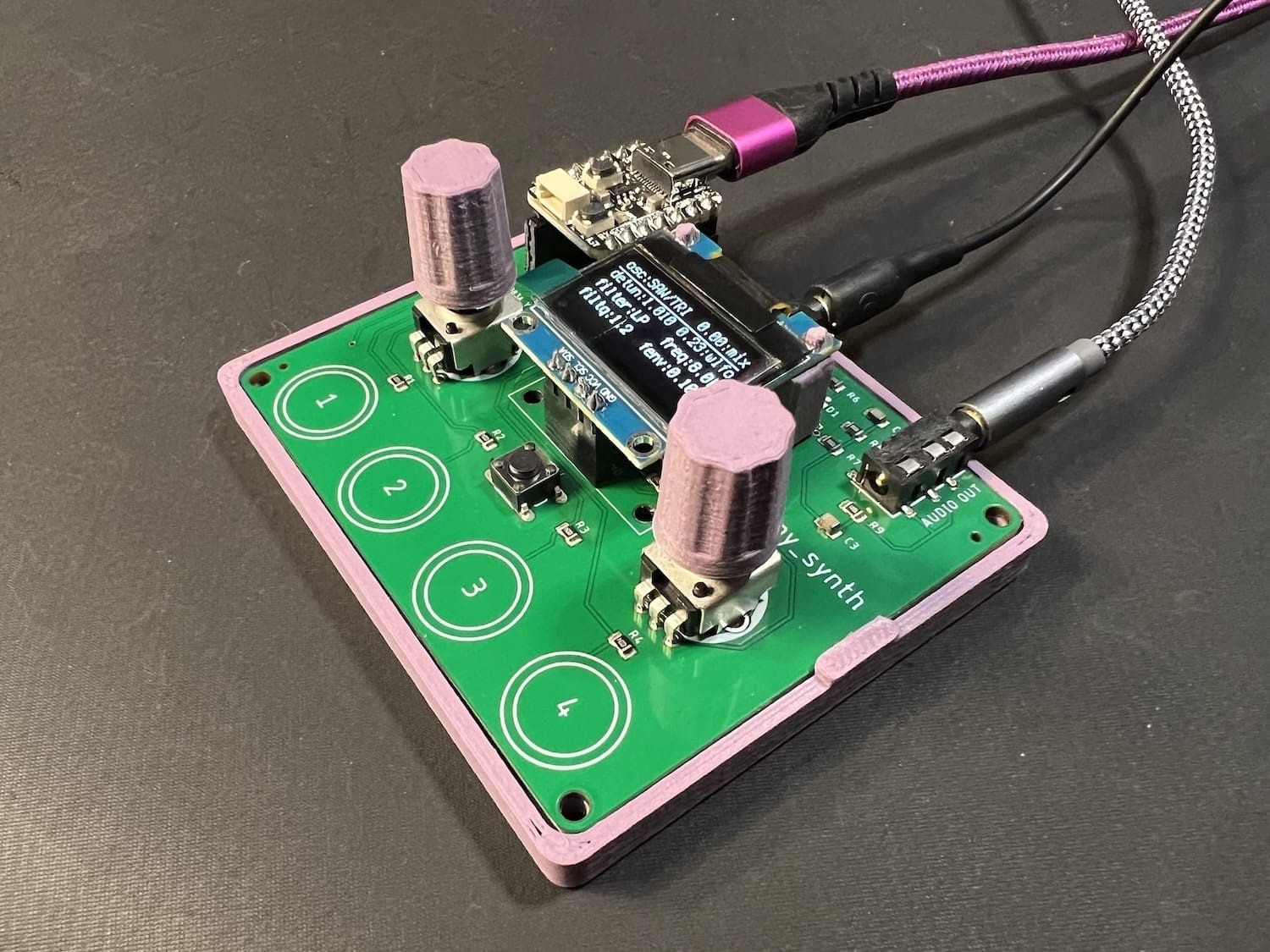
I wanted to go back to my Pico Touch Board PCB Design and see if there was a way to make it more stand-alone. The original design was to make it a MIDI controller, but that isn’t the only option.
https://makertube.net/w/tADSyrPrUdR1mx7yKRXZTC
Warning! I strongly recommend using old or second hand equipment for your experiments. I am not responsible for any damage to expensive instruments!
These are the key Arduino tutorials for the main concepts used in this project:
If you are new to microcontrollers, see the Getting Started pages.
Parts list
The Circuit
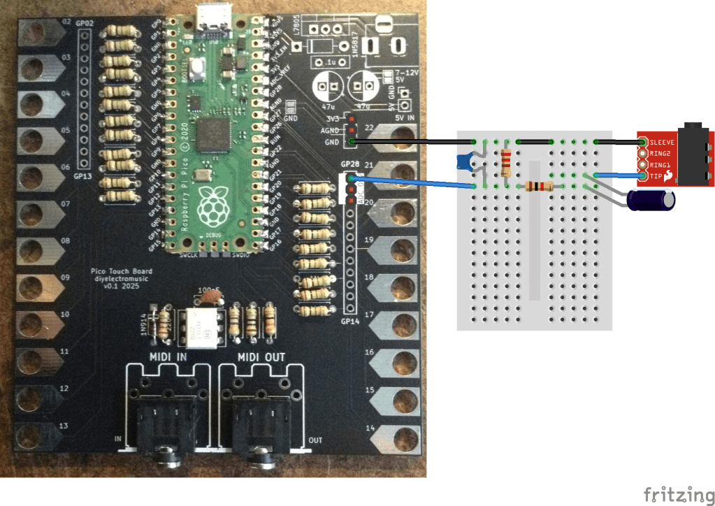
Most of the GPIO are linked out to the touch pads, but the three analog inputs are still available. They are added on to the header on the right hand side of the board at the top, so we can use one of these as an audio output.
Initially, I thought of connecting it to an 8Ω speaker. If I was using an Arduino then I’d use a 220Ω resistor in series to limit the current to less than 20mA. But as I’m using a Pico, the maximum current has to be a lot less. I seem to recall it is a little complicated, and there are some options, but I have a figure of around 4mA that I tend to work to. It is also running at 3.3V, which means that it would need an in series resistor of 3.3 / 0.004 = 825Ω. This would work, but the speaker will be really quiet!
So I ditched that idea (there is a software reason too, but I’ll talk about that in a moment) and went straight to a PWM output with a low-pass filter to try to give me some vaguely useful as a line-out signal.
I’ve not done the calculations, but instead went a bit “hand-wavy”, combing a 1K and 220Ω resistor to drop the voltage, along with a 100nF capacitor. I’ve also added a 22uF capacitor to remove the DC bias.
That seems to give me something useful, but as you can see from the trace below of a square wave PWM output, there is a lot of room for improvement!
Update
Ok, so going back and doing this semi-properly as per my notes from Arduino PWM Output Filter Circuit, I can see that the 1K and 220Ω resistors can be treated as a 180Ω equivalent (take them as two in parallel) for the filter circuit, which means a cut-off of around 8kHz which ought to be pretty good….
But reducing a 3V3 signal to around 20% leaves for quite a low level of audio – around 660mV peak to peak. It would probably be better to aim for a reduction of around a half.
Using a 1K and 500Ω resistor would be an equivalent resistance of 333Ω, so putting that into a low pass filter calculator gives a cut-off frequency of around 5kHz for a 100nF capacitor.
Weirdly the only thing that really seems to improve things is to raise that capacitor value to 1uF. My calculation would suggest a cut-off frequency of around 480Hz which is pretty small for an audio signal. But it seems to work.
The PWM frequency I was seeing was coming in at around 120kHz so should be plenty high enough to get filtered out. In the Circuitpython code, it is apparently chosen to support the number of bits required at the base clock frequency whilst being inaudible. For the RP2040 running at 125MHz, and with the chosen 10 bit resolution (more here) this is:
A 5kHz (or even 8kHz) cut-off I thought ought to be fine, but Davide Bucci on Mastodon explained for me:
“120kHz is 25 times 4.7kHz, that is about 1.4 decades and with a first-order filter you have a tad less than 30dB of attenuation, that is not a lot. A signal at 3.3V peak to peak at 120kHz becomes about 100 mV on the output after the filter.”
So switching to 1uF, as Davide explains: “if you put 1µF, you are indeed filtering a decade lower, therefore you gain 20dB in the attenuation and the 100mV become 10mV, much less noticeable.”
The alternative is to repeat the 1K+100nF stage and add a second order filter which also seems to work pretty well.
The final circuit that works fine for me at present, will be on of the following.
The first is less components but assumes that the frequencies won’t go much about ~1KHz or so. That is ok for my current setup but would limit the audio range a fair bit.
This is the output of the two-stage filter. It is so much better!
The Code
I wanted to stick with Circuitpython, so my initial thought was to use simpleio.tone() to generate a tone based on a frequency from an IO pin. However, this has the problem that the code is blocking whilst the tone is playing which isn’t very useful.
Instead I went straight to synthio. It turns out that using synthio was actually a lot easier than the “simple” simpleio…
Here is the basic code to generate an ASR-shaped square wave on a PWM audio output on GPIO 28 based on the touch pads as input.
import board
import touchio
import synthio
import audiopwmio
from adafruit_debouncer import Debouncer, Button

audio = audiopwmio.PWMAudioOut(board.GP28)
synth = synthio.Synthesizer(sample_rate=22050)
audio.play(synth)
synth.envelope = synthio.Envelope(attack_time=0.1, release_time=0.6, sustain_level=1.0)

touchpins = [
    board.GP2, board.GP3, board.GP4, board.GP5,
    board.GP6, board.GP7, board.GP8, board.GP9,
    board.GP10, board.GP11, board.GP12, board.GP13,
    board.GP14, board.GP15, board.GP16, board.GP17,
    board.GP18, board.GP19, board.GP20, board.GP21, board.GP22
]

THRESHOLD = 1000
touchpads = []
for pin in touchpins:
    t = touchio.TouchIn(pin)
    t.threshold = t.raw_value + THRESHOLD
    touchpads.append(Button(t, value_when_pressed=True))

while True:
    for i in range (len(touchpads)):
        t = touchpads[i]
        t.update()

        if t.rose:
            synth.press(60+i)

        if t.fell:
            synth.release(60+i)
I did experiment with overclocking the Pico to give double the PWM frequency, using
microcontroller.cpu.frequency = 250_000_000
But although this did double the PWM frequency to around 244kHz, it didn’t seem to make much difference for the filtered signal.
Battery Power
One last thing I wanted to explore was if it was possible to power the touchboard with batteries. I left in a number of power options, so for this one I’m using the 5V/GND pin header. I’ve included a couple of capacitors for smoothing, and need to add the 1N5817 diode as shown below.
This requires the following additional components:
The 5V/GND header pins connect to the Raspberry Pi Pico’s VSYS pin via the Schottky diode. The 1N5817 has a typical voltage drop of 0.45V, so combined with the Raspberry Pi’s accepted input voltage of 1.8V to 5.5V this means that ideally two or three AA batteries (at 1.5V each) would work. Four 1.2V rechargeables might be an option too.
It might be possible to get away with four 1.5V AAs, but that would give an input voltage of just over 5.5V, so I think that is probably pushing things too far. It might be a good use for some spent AAs though that are no longer reading a full 1.5V…
One of the downsides of battery power is that the touch works best when your fingers are at the same GND potential as the board. It works best if the GND pin of the (unpopulated) barrel jack is touched when using the board.
Closing Thoughts
With hindsight it would have been useful to have included a simple PWM output stage on the original board, but it is relatively straight forward to add one.
It might even be worth me making an add-on board that will connect to the header pins of the power and analog pins containing the simple passive filter components.
What is pretty impressive though, is how easy it is to use synthio with Circuitpython.
Kevin

ooh it's actually working pretty well now. It can play an arpeggio from a .python file (using sleep to pace the notes) or be used interactively.
branch is updated. My latest tester script is https://gist.github.com/jepler/2378eb9c925707d6d52e757b4374f23e
My Raspberry Pi Pico 2-based Dub siren now has a simple synth engine in addition to a sample engine, so its sounds now range from classic siren sounds to air horns and vocal snippets.
In this short video I show off the synth engine: 🎹🔈🎶
https://v.basspistol.org/w/qmjJ3TY8Q8mEzigVywDXmt
thx again 2 @todbot
And if you haven't seen it yet check out this video for yesterday's exploration of the sample engine: 📯🔈🎶
https://v.basspistol.org/w/pS4PrN9Wjo5eFP4hqFSpYr
#CircuitPython #AudioElectronics #SynthDIY #RP2350 #synths #SynthIO #BonkWave
The new audio effects libraries in CircuitPython are super fun. Here's a quick "taster" showing off some of them, part of my impending "Synthio Tutorial". Thanks Mark & Cooper for making them!
https://www.youtube.com/watch?v=nyv7XlQ1d00
#CircuitPython #synthio #audioeffects #synthdiy
Okay here’s a thing from an hour of goofin’: algorithmic music generator using a rotary encoder, a round TFT, and an I2S DAC in CircuitPython
https://www.youtube.com/watch?v=cCTPtk6KQQk
code: https://gist.github.com/todbot/7dc50b8de8db03638a9a291e9132b488
#CircuitPython #RP2350 #Pico2 #synthio #RaspberryPiPico2 #RaspberryPiPico
Paul got me a CircuitPython synthio shirt! Thanks @prcutler! It’s a wonderful #CircuitPythonDay2024 present! #CircuitPython #synthio https://hachyderm.io/@prcutler/112972142726716429

Here it comes, #CircuitPythonDay2024!
In celebration, a sketch that somewhat recreates the THX "Deep Note" sound on SparkFun Pro Micro #RP2350.
The messy code: https://gist.github.com/todbot/046b1c8243002ef76c5e2fabae84ba0e
#CircuitPython #synthio #RaspberryPiPico
The “picotouch_drumcard” boards showed up today! I put some software on it too. A few gotchas in my design but I can make it work. Now on to sample playback, since this is labelled a drum machine after all
#CircuitPythonDay2024 #CircuitPython #raspberrypipico #synthio
Built a little test rig for #circuitpython #synthio projects with a WaveShaweRP2040 Zero.
it does not look beautiful but it is indeed packed with stuff
I made a little 3d-printable case for my “qtpy_synth” test board to help me play with CircuitPython synthio (and Arduino Mozzi). It works pretty well, I like it better than the standoffs I originally started with. And now can have some cool matching 3d-printed knobs! https://www.printables.com/model/757087-case-for-qtpy_synth-circuitpython-synthesizer
more about qtpy_synth: https://github.com/todbot/qtpy_synth
#CircuitPython #synthio #rp2040 #qtpy #synthDIY
A little demo of a project I've been working: I made synthesizers for every attendee of our Sketching in Hardware conference! It was a lot of fun "infecting" people with little musical noise toys. It's called "picotouch_synth" and it's an evolution of the CircuitPython synthio on Raspberry Pi Pico stuff I've been doing for a while now
https://www.youtube.com/watch?v=0FgqWdkIjWM
more details: https://github.com/todbot/picotouch_synth
#CircuitPython #synthio #raspberrypipico #rp2040 #synthDIY
Great use of #SynthIO on #CircuitPython in this @adafruit guitar synth project by @ecken, @videopixil and @blitzcitydiy 🎸 🔈 🎶 🤘
Check out the fun video on their learn guide at https://learn.adafruit.com/guitar-synth-with-circuitpython-synthio
This new @adafruit Learn Guide to #SynthIO by @johnedgarpark looks really detailed and interesting (and of course features several of @todbot's projects). Great stuff!
https://learn.adafruit.com/audio-synthesis-with-circuitpython-synthio
Video of wavetable scanning using this new visualization technique. I love it! The resulting images are so beautiful and I'm finding the visualization really useful. Making me rethink my little synth toy designs
https://www.youtube.com/watch?v=O9iZOytzOHg
code: https://gist.github.com/todbot/d1034a677e62a4b9546ff3652f4b2114
#CircuitPython #wavetable #synthio #pygamer #synthDIY
I'm working on visualizing wavetables for CircuitPython synth stuff. Can you match the image on the left and right? Pretty cool but wow such a different way to see these waves! (each horizontal line is one waveform from the wavetable) The Pygamer is a great tool for this exploration since it has (albeit, noisy) audio outs in addition to screen + keys
#CircuitPython #wavetable #synthio #pygamer


The CircuitPython synthio panel was a lot of fun! Thank you @prcutler for organizing & hosting. Thanks to panel members John Park for the Intro to Synthesis at the start of the panel, @kattni@octodon.social for {musical/educator/synth}-using observations, @stylus@octodon.social for synthio deep knowledge, and to @adafruit for making it all happen! Here's a recording of the livestream: https://www.youtube.com/watch?v=SC4hUUfxVB0
#circuitpython #synthio #synthdiy #synthesizer
CircuitPython synthio panel happening now! #circuitpython #synthio
https://hachyderm.io/@prcutler/110905939632072545
New synth who dis?
Another toy to play with CircuitPython synthio
https://www.youtube.com/watch?v=9U2Dn7ckdbs
https://github.com/todbot/pico_test_synth
#circuitpython #raspberrypipico #synthio #synthdiy #rp2040