It's projects like this that give me hope for a new #Psion SSD based around the RP2350.
https://hackaday.com/2025/12/06/emulate-roms-at-12mhz-with-pico2-pio/
It's projects like this that give me hope for a new #Psion SSD based around the RP2350.
https://hackaday.com/2025/12/06/emulate-roms-at-12mhz-with-pico2-pio/
How I Built a Pico W Remote to Trigger My Alexa Routines
Have the #RaspberryPiPico SDK PDFs vanished from the Raspberry Pi website? I’m getting 404.
Atari 2600 Cartridge Emulation
I’ve been messing around with the Atari 2600 and at some point stumbled across the “Picotari” 2600 cartridge by Nick Bild, which emulates a ROM cartridge for the Atari 2600 using a Raspberry Pi Pico.
You might not recognise the name Nick Bild, but you will be very familiar with some of their projects which seem to blend quirky concepts with some neat engineering solutions. Most of their interesting projects will make it to Hackaday and similar places.
The Picotari was developed to be able to create a pixelated “photo” slideshow on an Atari 2600 turning it into a low-res digital photo frame. One of their recent projects links an LLM into a vintage speech chip to recreate the WOPR talking in War Games. More of their projects here: https://www.youtube.com/channel/UCcUMG56v69cuzsbM0gaSsOQ
There are some details of the Picotari build as part of the project notes on hackaday.io: https://hackaday.io/project/202729-atari-2600-digital-photo-frame/details and it also references another one of their projects: https://github.com/nickbild/picoROM.
Although there are Gerber files provided for the PCB used, and a high level description of the photo frame project, I don’t really have the expertise to follow along fully. I was finding it quite difficult to pin down the actual details of how the project was working, so this is me using that as a basis and guide as I dig into the innards of the Atari 2600 cartridges and documenting what I found out on the way.
The Picotari PCB
The Picotari PCB looks perfect for what I’d like to do, so I decided to see if I could work out what is going on. I started by examining the Gerber files in KiCad’s Gerber viewer. Some points to note about the PCB:
KiCad has an option to pull the Gerber layers back into the PCB editor tool, so I did that to make things a little easier to work with. Note that I had to make sure it included all four layers of copper and that they mapped through into sensible layers in the PCB editor too (I ended up with F, In1, In2, B copper layers with In1 as the ground plane).
From this, I can note the following:
From earlier browsing around I noticed that there was a pin definitions file in the PicoROM GitHub repository that maps GPIO to data and address lines as follows:
And that seems to mirror what is going on here. PicoROM is designed to emulate 27C256 devices, hence requiring 15 address lines: 32K devices require an address space $0000-$7FFF, but with GPIO 12, 13 and 14 fixed to GND that reduces down to 4K.
Mapping all these back onto some existing KiCad footprints and adding some labels gives me the following.
So I can expand on my notes, now noting:
Looking in a bit more detail at the level shifting, I can see from the 74LVC245 datasheet:
With DIR tied HIGH, it would appear that whatever is presented on the A lines should appear on the B lines (at the voltage level of VCC). In fact the Adafruit product page describes it thus:
“We suggest checking out the 74LVC245 datasheet for details but essentially: connect VCC to your logic level you want to convert to (say 3.3V), Ground connects to Ground. Wire OE (output enable) to ground to enable the device and DIR (direction) to VCC. Then digital logic on the A pins up to 5V will appear on the B pins shifted down to the VCC logic.”
This seems the wrong way round for me. I’d have thought that as these are the (to be read by the Atari) data lines, these should be going from lower voltage Pico logic (on the B bus) to higher voltage Atari logic (on the A bus).
What is also curious is that there is no logic shifting on any of the address lines. I would have thought these would be the inputs (from the Pico point of view), but they seem to be running natively from 5V logic levels and are being fed into the Pico.
I do note that the original PicoROM breadboard used three 74LVC245 chips, but couldn’t find a schematic for either build: https://github.com/nickbild/picoROM
On going back to the original project pages, I noticed this:
I’ve not found any details of what the bodge actually was, but I think there is a good chance that the DIR pin is now connected to GND via that bodge wire to reverse the direction of the device. DIR = LOW means go from B (3V3) to A (VCC or 5V). That is quite a tricky bodge though as the pad for that pin of the chip has 4 tracks connected to it linked to VCC…
As I understand things, the LVC245 should run at the “output” logic level, which in this direction is 5V. But the data suggests that ideally VCC would be 1.8V to 3.6V, but it does say it will accept anything up to 5V as an input. The absolute maximum ratings for VCC (for an SN74LVC245 at least) are -0.5V to +6.5V, but the recommended values are as follows:
The point to note is the Input and Output voltages: the input is always 0 to 5V, but the output will be 0 to VCC.
So at this stage in my understanding, it seems like the 74LVC245 would be great for 5V logic in, 3.3V logic out (when powered by VCC=3.3V) but there are probably alternatives for going the other way. But as the absolute max for VCC is still more than 5V, using it in this direction is probably ok, but there aren’t figures in the datasheet for what high-level and low-level look like for VCC=5V. I guess using a 3.3V high for a VCC=5V must work ok though and the output will be at 5V.
That still leaves the puzzle about the levels of the 12 address lines used. It looks like the original PicoROM had level shifting on them all, but for this board the 5V from the atari goes directly into the Pico GPIO pins.
There is some interesting discussion about the 5V tolerance of the RP2040 here: https://www.derekfountain.org/zx_pico_5v.php
The summary is that the Pico can accept 5V as long as it is powered. But until its 3V3 power is active, it should not see anything more than 3.6V. So this is effectively a power-on race condition – will the Pico see 3V3 power before the Atari sends it some data?
At the time of writing, it has just been announced that there is a new version of the RP2530 which, as well as fixing the now well-known bug with the internal pull-down resistors, is also apparently now essentially 5V tolerant. That might be one option if I can get a Pico with the new version of the chip installed.
Or maybe I should be adding my own level shifting on the address lines.
To be honest, at this point I am wondering if it is worth designing my own PCB building on the above knowledge now gained. I’m just not sure I’m up to trying to design a four-layer board yet. It would be a lot to ask to try to route between the Atari connector and a Pico with just two layers I think.
Maybe I’ll just accept that it seemed to work, so just pick out a sacrificial Pico and leave it to take its chance with the potential 5V inputs…
This is my finished build. Note – I added some insulating tape over the DIR pad of the LVC245 and bent the pin from the socket out to allow me to solder a jumper wire to the GND link of the nearby capacitor.
Atari 2600 Cart Details
There is a lot of detail online about the design and implementation of cartridges for the 2600 system. There were developments of the basic system for the 400/800 and later systems, but they all remained essentially backwards compatible with what went before them for the 2600.
References:
Key details:
There are some ROM switcher options out there that allow different 2K/4K ROM images to be stored in a larger EEPROM and presented to the Atari depending on the settings of certain jumpers.
Here are a couple of options:
And of course there were a number of “ROM scanners” and switchers back in the day that allowed choosing between different cartridges. There is a great write-up of one of them here: https://www.the-liberator.net/site-files/retro-games/hardware/Atari-2600/atari-2600-marjac-rom-scanner-1983.htm
PicoROM Code
All the code to allow the Pico to respond as a ROM device for the Atari can be found here: https://github.com/nickbild/picoROM. There are a few things to note:
The best reference for building code for an Atari 2600 is “Dr Boo’s Woodgrain Wizardry” here: https://www.taswegian.com/WoodgrainWizard/tiki-index.php?page=Start-Here
It recommends using the Stella emulator for ease of development. This would get to the point of having a binary ROM image which can then be built into the Pico using the script mentioned above, building using the Pico SDK.
The actual running code on the Pico is pretty straightforward:
void main () {
    while (true) {
        put_data_on_bus(get_requested_address());
    }
}

int get_requested_address() {
    // Return only first 15 bits.
    return gpio_get_all() & 32767;
}

void put_data_on_bus(int address) {
    // gpio mask = 8355840; // i.e.: 11111111000000000000000
    // Shift data 15 bits to put it in correct position to match data pin defintion.
    gpio_put_masked(8355840, rom_contents[address] << 15);
}
That is basically it. As fast as possible.
Recall that GPIO0 to GPIO14 are the address lines, hence only grabbing the first 15 bits from the gpio_get_all() call. And GPIO15 to GPIO22 are the data lines, hence masking off the correct 8 bits for gpio_put_masked().
Building PicoROM
First I updated my Pico SDK environment by doing a ‘git pull’ in the sdk, extras, examples, and picotool areas. All my pico stuff is in a src/pico area:
~/src/pico$ cd pico-sdk
~/src/pico/pico-sdk$ git pull
~/src/pico/pico-sdk$ cd ../pico-extras
~/src/pico/pico-extras$ git pull
~/src/pico/pico-extras$ cd ../pico-examples
~/src/pico/pico-examples$ git pull
~/src/pico/pico-examples$ cd ../picotool
~/src/pico/picotool$ git pull
Then I cloned the original PicoROM build and the Picotari project, so I had something to work with.
~/src/pico$ mkdir picorom
~/src/pico/picorom$ cd picorom
~/src/pico/picorom$ git clone git@github.com:nickbild/atari_2600_digital_frame.git
~/src/pico/picorom$ git clone git@github.com:nickbild/picoROM.git
Then I tried to build picoROM as a starting point. And failed.
I don’t know if things changed with a more recent SDK or I just don’t know what I’m doing (which is almost a certainty with the Pico SDK – I find it quite impenetrable and don’t use it enough to get past that right now), but in the end this is what I had to do to build picoROM:
~/src/picorom$ cd picoROM
~/src/picorom/picoROM/picoROM$ rm CMakeCache.txt
~/src/picorom/picoROM/picoROM$ rm Makefile
~/src/picorom/picoROM/picoROM$ rm -rf CMakeFiles
Then I had to recreate some of the basic boilerplate files and entries, which I cribbed in my ignorance, from a previous project.
~/src/picorom/picoROM$ cp ../../pico-sdk/external/pico_sdk_import.cmake .
cmake_minimum_required(VERSION 3.13)
include(pico_sdk_import.cmake)
project(picorom LANGUAGE C CXX ASM)
pico_sdk_init()
Note that without detailing that assembly language is required in the project() directive, you’ll get an error something like “CMake Error: Error required internal CMake variable not set, cmake may not be built correctly. Missing variable is: CMAKE_ASM_LINK_EXECUTABLE”.
Create a build area.
~/src/pico/picorom/picoROM$ mkdir build
Then I can finally run cmake and then attempt a build…
~/src/pico/picorom/picoROM$ cd build
~/src/picp/picorom/picoROM$ cmake ..
~/src/pico/picorom/picoROM$ make
This indeed does appear to give me a pico_rom.uf2 file. I can’t test this one as it is an application for his bespoke DIY computer, but now I know I can build the original project, I repeat the above for the Atari picture frame app…
To start with, there is no associated build infrastructure, so I just copy the missing files from the picoROM area and rebuild.
~src/picorom$ cd atari_2600_digital_frame
~src/picorom/atari_2600_digital_frame$ cp ../picoROM/pin_definitions.h .
~src/picorom/atari_2600_digital_frame$ cp ../picoROM/CMakeFiles.txt .
~src/picorom/atari_2600_digital_frame$ cp ../picpROM/slower_boot2_padded_checksummed.S .
~src/picorom/atari_2600_digital_frame$ cp ../../pico-sdk/external/pico_sdk_import.cmake .
The CMakeFiles.txt file needs a minor update to rename rom.c to pico_rom.c. Then I tried a build
~src/picorom/atari_2600_digital_frame$ mkdir build
~src/picorom/atari_2600_digital_frame$ cd build
~src/picorom/atari_2600_digital_frame/build$ cmake ..
~src/picorom/atari_2600_digital_frame/build$ make
And copied the resulting pico_rom.uf2 to the Pico on the Picotari PCB.
Amazingly I got a display! But it was off – there was obviously something odd going on somewhere…
Then unfortunately it stopped working. I thought I’d killed my 2600 junior as it wasn’t working even with a normal cart, so I dug out my original woody 2600 with an original cart but that wasn’t working either, so concluded it was the TV or at least the TV’s tuning. It turns out that the TV struggles to spot a signal from time to time on the analogue channels, but switching preset channels out and back seems to wake it up again.
The photo frame code is meant to return different bytes from the embedded graphic when a specific address is read. The cart itself “believes” it is just continually reading the same byte. At least that is my understanding of how it is meant to work.
So to me, this looks like a data ordering issue in the code somewhere. As I’m not particularly interested in the picture frame application, this was just a test with a supposedly known-good application, I’m happy that the hardware appears to be essentially working fine.
But just thinking about this for a moment. It could be an issue with scan line timings. It isn’t clear to me if the original project is meant for NTSC or PAL, but given the author is in the US (I believe), I suspect NTSC. It may well be that the Atari ROM code assumes the 30 frame/s update rate of NTSC rather than 25 frames/s for PAL and that messes with the timing of the data. The refresh rates are actually 60Hz and 50Hz but it is an interlaced display so two scans are required per frame of image. PAL images are also 625 lines compared to NTSC’s 525.
With the Atari, all this is pretty important as the CPU has to manage everything to do with the display, timing and all, alongside anything else it is trying to do (see the excellent book “Racing the Beam” for some of the amazing tricks people came up with for getting the most out of this system!).
Of course, it could also be nothing to do with this. At this point I just don’t know enough personally about Atari code to delve into it to see if I could correct it.
I’d like to know if I could get this working, but I suspect that may be a project for another time.
Game ROM
One final test – could I build in an existing game ROM and have that boot and run?
I grabbed a ROM collection off the Internet and found the ROM for space invaders, then built that into the original PicoROM code using a translate python script from the Atari repository.
~/src/pico/picorom/picoROM$ python ../atari_2600_digital_frame/translate_bin2rom.py spaceinv.bin > romdata.c
Then just had to replace the original rom_contents[] = XX lines from rom.c with the new lines in romdata.c and build. There are less lines in the space invaders ROM, but once built and plugged into the Atari, sure enough, I get to see Space Invaders up and running on the display.
I’m not getting sound at the moment, but that could be any combination of an odd ROM or slightly incompatible version (there were about 5 to choose from!) or the TV tuning, which I still have little confidence over.
But as the game does seem to boot and run and is playable, so I’m happy that the basic system seems to be working.
Update: It was TV tuning. Fiddling around and I finally got some sound! 🙂
Conclusion
This is a very clever project and I’m really grateful for Nick Bild for releasing the details of their build.
I feel like I’ve got a bit more of a handle on what is going on now and have ended up with a really useful starting point for a few of my own project ideas.
My next step is to work out how to build a custom Atari ROM executable of my own.
Kevin


CJMCU AS3935 - Simular rayos con pulsos PWM
En este vídeo explico cómo utilizo un microcontrolador secundario para testear el sensor de rayos CJMCU-AS3935 para simular con pulsos PWM los pulsos electromagnéticos de un relámpago o rayo y de esta forma asegurarnos que nuestro dispositivo funciona correctamente o testear el código que desarrollemos para utilizar el sensor.
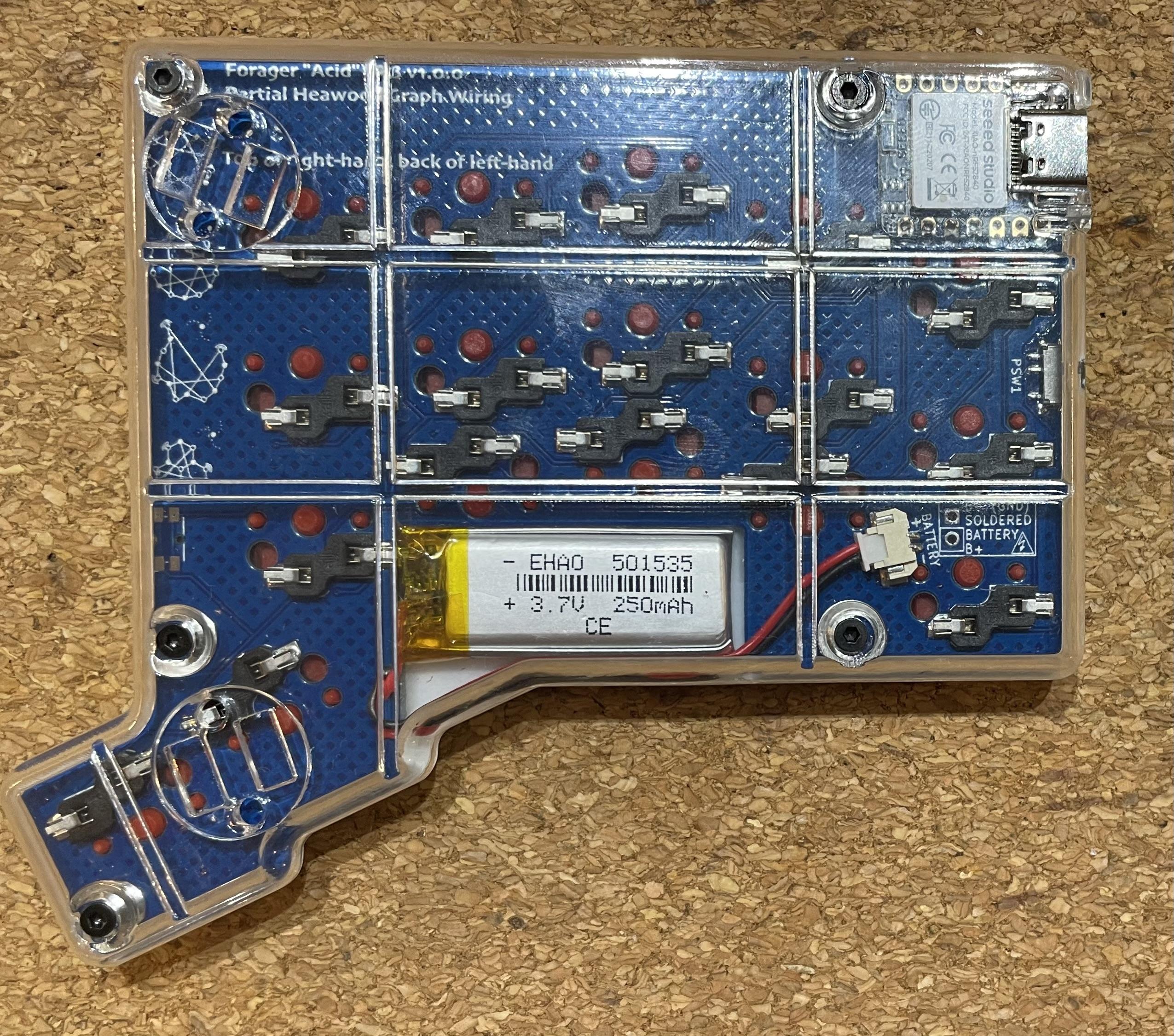
I am slowly getting better at soldering, 4 out of 7 successful #MechanicalKeyboard PCBs now - all three of my diode-free #GraphTheory wired keyboard PCB designs have worked (eventually) ⌨️🎊
1️⃣ #RaspberryPiPico #RP2040 ‘Gamma Omega TC36K’ (USB only) http://astrobeano.blogspot.com/2025/08/my-first-self-built-computer-keyboard.html
2️⃣ #ProMicro #nRF52840 BLE ‘Gamma Omega Hesse’ https://astrobeano.blogspot.com/2025/10/hesse-diode-free-bluetooth-keyboard.html
3️⃣ #SeeedStudio #Xiao #SplitKeyboard BLE split Forager ‘Acid’ http://astrobeano.blogspot.com/2025/10/partial-heawood-forager-keyboard.html
I've been intrigued by the idea of #RISCV recently but I've never really dabbled in low-level electronics. Any recommendations for a small #SBC I can try it out with? Something similar to an #Arduino or #RaspberryPiPico would be preferred.
今更だけど
ラズパイPico、PIOなんてあったの???
そう言えば RP2040 のデータシート、読んだ事なかったかも… :blobdoggoglarethink:
やる事やったら読んでみよう!
If you’ve written a Windows application that can read the Serial Number/Unique ID, or even the Vendor ID or Product ID of a microcontroller board (Pi Pico in my case) I’d appreciate any pointers.
#arduino #RaspberryPiPico #piPico #esp32 #windows #microcontroller #microcontrollers
And it finally works, after much head-scrstching,.many (many!) dry joints, a few broken wires and having to switch GPIOs because #tinyusb seemed to want to hold on to gpio1+2 despite my best efforts, my #MGT #SamCoupe USB-HID mouse adaptor prototype (based loosely on the #RP2040Mouse project) is working
It has taken me an hour to get this fecking thing to light up and do anything at all.

I finally wrote a blog post on my DCO design based on the Raspberry Pi Pico. It's one of my older designs and the different pieces are all over and this brings it all together. I think it's still a great project which combines hardware and software. Enjoy!
https://polykit.rocks/open-source-digitally-controlled-oscillator-dco-juno-style
#synth #synthdiy #dco #raspberrypipico #oscillator #midi #roland #juno

Has anyone managed to build Pico code on macOS on Apple Silicon (M4 Pro specifically) under Tahoe? Had all sorts of obscure problems that seemed to be interactions between the Xcode compiler and the Pico compiler (from MacPorts).
Gave up and built it in an Intel Debian docker container in the end.
This is a fun thing to do.
Using a 125MHz 32-bit dual Cortex M0+ to pretend to be the ROM for a 10Hz 4-bit CPU... As you do...
https://emalliab.wordpress.com/2025/11/15/td4-4-bit-diy-cpu-part-6/
TD4 4-bit DIY CPU – Part 6
Having now successfully built my own version of the TD4 4-bit CPU in Part 5, I’m now chewing over some of the ways I’d like to try to expand it.
I already have a list of others extended projects at the end of Part 4, so I might be drawing on some of them for inspiration moving forward. Many of these are very similar projects, but with a completely different architecture. But really at this stage rather than build a different, more capable, 4-bit CPU from someone else’s design, I’m interested in seeing how far the TD4 design can go. So, ultimately, like all my projects, the fun here is in the reinventing and learning on the way.
One of the questions I have is can I replace the DIP switches with something that can provide the data in a better way? This would be particularly critical if I expand the address space in the future. A ROM is the obvious option, but something more dynamic might be an interesting experiment too.
This post looks at options for replacing the DIP switches with microcontrollers.
Now I feel like I really ought to state right up front that this is a pretty ludicrous thing to do.
At the more charitable end of the endeavor I’m using a 16MHz 8-bit AVR microcontroller with 2kB of RAM to serve up 16 8-bit values to a 10Hz 4-bit CPU.
At the most extreme end I’m using a 125MHz, dual-core, 32-bit ARM Cortex M0+ CPU with 264 kB of RAM running an entire interpreted programming environment requiring (probably) millions of lines of low-level code to implement it, to do the same thing.
So why bother? Well – why not?
TD4 without the ROM
To interface to a microcontroller, I’m after two things:
The best place to get at these signals is on the interface to the ROM itself – the 74HC540 octal line driver, and 74HC154 4-to-8 line decoder.
Conveniently, these signals can be broken out quite easily on my board as shown below.
The pink shaded area shows which components are needed for a ROM-less build. The two yellow highlights show where headers should be soldered to permit access to the address lines (top) and data lines (bottom).
In this build, the following components are omitted from the full board:
I’ve used 6-way and 10-way pin header sockets to allow me to patch in a microcontroller. This allows for each header to conveniently include 5V and GND too. I’ve included the USB socket for power to the PCB but expect I’ll probably power the board via these 5V and GND links from the microcontroller.
Using Arduino
The natural choice here is to use one of the older Arduino boards, as these are all 5V IO which makes interfacing with the 4-bit CPU fairly straight forward.
Using Arduino direct PORTIO should also make it pretty trivial to read address lines and write the data. I’ve configured the connections as follows:
TD4 SignalArduino GPIOArduino PORTIOA0A0PORTC:0A1A1PORTC:1A2A2PORTC:2A3A3PORTC:3D0D8PORTB:0D1D9PORTB:1D2D10PORTB:2D3D11PORTB:3D4D4PORTD:4D5D5PORTD:5D6D6PORTD:6D7D7PORTD:7I’m avoiding D0/D1 (PORTD[0:1]) and D13 as they all have other hardware attached (serial port and LED in this case).
Accessing the data corresponding to any specific address is as simple as follows:
uint8_t ROM[16];

loop:
    unt8_t addr = PINC & 0x0F
    PORTB = (PORTD & ~(0x0F)) | (ROM[addr] & 0x0F);
    PORTD = (PORTD & ~(0xF0)) | (ROM[addr] & 0xF0);
The code could be simplified if I didn’t mind trashing whatever is configured for the other GPIO pins via the PORTIO, but it is good practice to preserve those values when only writing to a subset of the IO ports.
In the final code below, I’ve included a toggle for A5 which allows me to do some timing measurements too.
uint8_t ROM[16] = {
    0xB1, 0x01, 0xB2, 0x51,
    0xB4, 0x01, 0xB8, 0x51,
    0xB4, 0x01, 0xB2, 0x51,
    0xF0, 0x00, 0x00, 0x00
};

void setup() {
  DDRB |= 0x0F;
  DDRD |= 0xF0;
  DDRC |= 0x20;
}

int toggle;
void loop() {
  if (toggle == 0) {
    toggle = 1;
    PORTC |= 0x20;
  } else {
    toggle = 0;
    PORTC &= ~(0x20);
  }

  uint8_t addr = PINC & 0x0F;
  PORTB = (PORTD & ~(0x0F)) | (ROM[addr] & 0x0F);
  PORTD = (PORTD & ~(0xF0)) | (ROM[addr] & 0xF0);
}
Running the code in a loop like this gives a scan frequency of around 500kHz and a response time of something like 2-3 uS for each read. That seems pretty responsive and I’m sure will be fine for a 10Hz CPU. And it is – it works great!
Using Circuitpython
One thing that would be really nice is a workflow that allows more of a “direct save to the CPU” approach to programming it. One option is to use a more modern microcontroller that supports a filesystem.
The obvious choice here is a 32-bit microcontroller that supports Circuitpython. But will IO in Circuitpython be fast enough to respond to the CPU? There is one obvious way to find out – give it a try.
There is another complication too – most Circuitpython boards run at 3.3V not 5V so that needs to be addressed too.
Level Shifting
I’m going to use a 74LVC245. The Adafruit product page puts it best:
“essentially: connect VCC to your logic level you want to convert to (say 3.3V), Ground connects to Ground. Wire OE (output enable) to ground to enable the device and DIR (direction) to VCC. Then digital logic on the A pins up to 5V will appear on the B pins shifted down to the VCC logic.”
This is an 8-way bi-directional bus transceiver and should be powered by 3V3, then the direction pin will determine the direction of the conversion as shown[ below.
Two devices will be required. The address lines will need a 5V to 3V3 conversion; the data lines will need 3V3 o 5V.
Here is how I’ve wired these up for a Raspberry Pi Pico:
The Pico is connected as follows:
CircuitPython ROM
The basic algorithm will be as follows:
ROM = [16 command byte values]

LOOP:
  Read four address lines
  Set data lines from ROM[address]
For performance reasons it would be best to optimise both the reading of the address lines and the writing of the data lines, ideally into a single access. But as this is for a CPU that runs at a maximum of 10Hz, so for now, I’m just going with simple and see how it goes.
import board
import digitalio

ROM = [
    0xB1, 0x01, 0xB2, 0x51,
    0xB4, 0x01, 0xB8, 0x51,
    0xB4, 0x01, 0xB2, 0x51,
    0xF0, 0x00, 0x00, 0x00
    ]

Tpin = digitalio.DigitalInOut(board.GP21)
Tpin.direction = digitalio.Direction.OUTPUT

A0pin = digitalio.DigitalInOut(board.GP10)
A1pin = digitalio.DigitalInOut(board.GP11)
A2pin = digitalio.DigitalInOut(board.GP12)
A3pin = digitalio.DigitalInOut(board.GP13)

D0pin = digitalio.DigitalInOut(board.GP2)
D0pin.direction = digitalio.Direction.OUTPUT
D1pin = digitalio.DigitalInOut(board.GP3)
D1pin.direction = digitalio.Direction.OUTPUT
D2pin = digitalio.DigitalInOut(board.GP4)
D2pin.direction = digitalio.Direction.OUTPUT
D3pin = digitalio.DigitalInOut(board.GP5)
D3pin.direction = digitalio.Direction.OUTPUT
D4pin = digitalio.DigitalInOut(board.GP6)
D4pin.direction = digitalio.Direction.OUTPUT
D5pin = digitalio.DigitalInOut(board.GP7)
D5pin.direction = digitalio.Direction.OUTPUT
D6pin = digitalio.DigitalInOut(board.GP8)
D6pin.direction = digitalio.Direction.OUTPUT
D7pin = digitalio.DigitalInOut(board.GP9)
D7pin.direction = digitalio.Direction.OUTPUT

def doOutput (data):
    if (data & 0x01):
        D0pin.value = True
    else:
        D0pin.value = False

    if (data & 0x02):
        D1pin.value = True
    else:
        D1pin.value = False

    if (data & 0x04):
        D2pin.value = True
    else:
        D2pin.value = False

    if (data & 0x08):
        D3pin.value = True
    else:
        D3pin.value = False

    if (data & 0x10):
        D4pin.value = True
    else:
        D4pin.value = False

    if (data & 0x20):
        D5pin.value = True
    else:
        D5pin.value = False

    if (data & 0x40):
        D6pin.value = True
    else:
        D6pin.value = False

    if (data & 0x80):
        D7pin.value = True
    else:
        D7pin.value = False

while True:
    Tpin.value = True
    addr = 0
    if (A0pin.value == True):
        addr = addr + 1
    if (A1pin.value == True):
        addr = addr + 2
    if (A2pin.value == True):
        addr = addr + 4
    if (A3pin.value == True):
        addr = addr + 8

    Tpin.value = False
    doOutput(ROM[addr])
I’ve included a timing pin to GPIO21 so I can see how long it takes to access the IO.
It turns out that it takes something of the order of 50-60uS to read the four address lines and something in the region of 70-80uS to write out the 8 data lines. The above simple Circuitpython code to do this is running with a frequency of around 7kHz.
Now at this point I ought to be reading through the datasheets for the ICs used in the CPU to check response times and timing tolerances so see if this is ok. But I didn’t bother with any of that as it all appears to work!
Conclusion
The Circuitpython is obviously a lot slower than the Arduino running optimised PORTIO code, even though the Circuitpython is running on a 125MHz processor compared to the Arduino’s 16MHz. Of course, if performance was critical then switching to direct GPIO access in C on the Pico would be a lot faster again. Even just having a way to do a single block-access of GPIO would probably make quite a difference.
But for this application, either as they are seem to work absolutely fine.
The ability to quickly edit the ROM contents is pretty useful with the Circuitpython. But I am now wondering how difficult it would be to have some kind of uploader to the Arduino over the serial port. There are only 16 bytes to transfer after all.
In fact it might even be possible to create a simple interactive assembler that allows code to be typed in over the serial port using proper word-based op-codes (like ADD, IN, OUT, etc). At the very least a simple serial port interface to type in numeric values would be relatively straight forward I think. It might also be possible to allow the microcontroller to reset the CPU too.
I’m not sure the added complications of logic shifting, etc, make it worth carrying on with a Pico version at this stage, so I think improving the Arduino is probably the way to go for now.
Kevin
#4bit #arduinoUno #circuitpython #portio #raspberryPiPico #td4


Raspberry Pi Pico clone, delivered from China, for CDN $2.59.
Madness.
"From now on, the cat drinks unleaded!"
#RaspberryPi #RaspberryPiPico #Pico #MCU #microcontroller #BloomCounty #IYKYK #cheap #clone #electronics #hobby #DIY
20 Easy Raspberry Pi Projects: Toys, Tools, Gadgets, and More! (1 ed)
https://ebokify.com/20-easy-raspberry-pi-projects-1-ed
🔥 Top 6 Raspberry Pi eBooks V2 for $20
https://ebokify.com/top-6-raspberry-pi-ebooks-v2
#raspberrypi #raspberrypi5 #rpi5 #raspberrypipico #raspberrypizero #raspberrypi4 #raspberrypi3 #raspberrypi4b #RP2350 #IoT #IoTProjects #Microcontroller #EmbeddedSystems
Envoyez un SMS 📱 et le #RaspberryPiPico s’illumine !
Projet 4G 🇫🇷 avec la #NadHATMK2 en #MicroPython : réception SMS, affichage OLED, LEDs animées 🎇
👉 https://www.framboise314.fr/4g-raspberry-pi-pico-nadhat-mk2-micropython

Commodore USB Keyboard Adapter Brings C64 Keys to Modern Systems
#Commodore64 #RaspberryPiPico #RetroComputing #C64 #OpenSource
https://theoasisbbs.com/commodore-usb-keyboard-adapter-brings-c64-keys-to-modern-systems/?feed_id=6405&_unique_id=69149363e239d