Cheap Max7219 Chainable LED Matrix
I can’t resist a cheap LED matrix, so when I stumbled across these 8×8 LED matrix displays with a Max7219 driver LED in this chainable form-factor for, get this, less than £1.50 each from electrodragon.com … well, I had to give them a go. It is a relatively simple circuit board to build, so there are very minimal instructions, but there are still a couple of gotchas that might catch out a beginner, so I’ve put together these notes whilst putting them together. By the way, I ordered 9 so I could eventually form a 24×24 LED square (3×3 of the matrices).
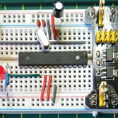
I started with the headers, then the discrete components, finally the chip. The only thing to note is the polarity of the electrolytic capacitor (of course – look for the + on the circuit board) and the orientation of the chip itself. Also note that ‘pin 1’ of the LED matrix sockets are indicated by a square pad in the top right of the circuit board (as seen from the top, with the writing the right way up). It is worth fiddling with the electrolytic prior to soldering to try to ensure it doesn’t poke out over the top edge of the circuit board – although if it does, if physically mounting boards next to each other, it will quite happily overlap into the next board.
The design suggests that all the header pins face upwards and that the jumpers are used on the top of the board to chain them together. however, I didn’t really want to have to take off the LED matrix every time I wanted to change how it was linked, so I opted to solder the connecting header pins to the underside of the board as shown. It also gets around the issue they describe on the product webpage about the LED matrix not really fitting snugly on the board. Mine fits nice and tight.
So all that remains is to add the LED matrix. As I said, pin 1 should be indicated on the matrix itself and is indicated on the circuit board by the square pad near the electrolytic capacitor.
In terms of making the thing work, it is relatively simple to connect up:
- CLK – D2
- LD – D3
- DIN – D4
- VCC – VCC
- GND – GND
Of course when chaining with jumpers DOUT goes to the next LED DIN. The other pins pair up.
There is a lot of arduino code for these types of driver chips – start here – http://playground.arduino.cc/Main/LEDMatrix.
I used the code from here to test my setup – http://playground.arduino.cc/LEDMatrix/Max7219 – as written this assumes the same pinouts as I describe above (i.e. CLK, LD, DIN on digital pins 2, 3 and 4).
You just need to set the number of chained displays at the top:
int maxInUse = 9;
(in my case) and get to work playing. The routines in the library provide a simple interface to setting rows on a single or all of the chained displays. maxSingle is meant for when there is just one display. maxAll displays the same value on all displays in the chain. maxOne will target a specific display (starting with display number 1 up to your last – 9 in my case).
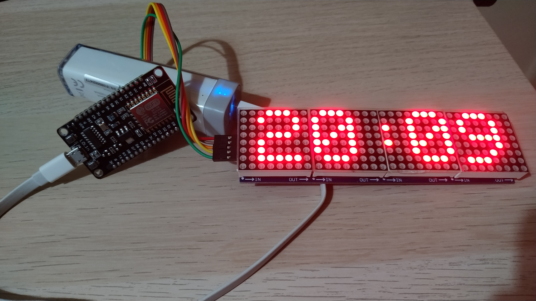
As you can perhaps see, this is using an Ardunio nano. With 9 boards cascaded, getting the PC to recognise the nano was plugged in was sometimes a problem – it often gave me a ‘there is a problem with your USB device’ error on Windows 7. It was fine with lesser numbers of matrices, so I guess there is a power issue with the nano struggling with the USB setup and initialising all 9 LED matrices at the same time. Temporarily disconnecting VCC from the LEDs when plugging in the USB seems to solve the issue for me.
As I eventually want to be setting an entire row of LEDs in a larger grid, the maxOne function is a little wasteful as it has to shunt null values to all of the LED displays you are not targeting – so calling it 9 times means writing 81 bytes out across the DIN pin just to actually set 9 bytes. Consequently it is possible to optimise it a little if you want to write an entire row to all displays in the same transaction.
Of course, if you refer back to the LedMatrix page, there are many other libraries that will do most of this for you, including Marco’s very complete library for scrolling text displays – http://parola.codeplex.com/ – but I quite like being able to see what the low-level code is actually doing to make things work.
I’ve therefore added a maxRow function as follows:
// Note: Sloppy code warning!// There is no checking here that *col is an array of// the correct length - i.e. maxInUse//// It should be defined and used as follows:// byte row[maxInUse];// // fill each byte of row with your data - row[0], row[1], row[2], etc.// // using one byte for each matrix in sequence// maxRow (1, &row[0]);//void maxRow (byte reg, byte *col) { int c=0; digitalWrite(load,LOW); for (c=maxInUse; c>=1; c--) { putByte(reg); putByte(col[c-1]); } digitalWrite(load,LOW); digitalWrite(load,HIGH);}But I haven’t mentioned the absolutely best feature of these little boards yet. And that is that they are almost exactly the same dimension as a 4-stud Lego brick. This means it was trivial to make a simple enclosure to hold my 3×3 grid and the nano.
I now have a really cool game-of-life running on my 24×24 LED grid. At this price, I have another 8 on order so I can take it to a 4×4 grid (with one spare).
Kevin
#arduino #ledMatrix #leds #lego #matrix #max7219