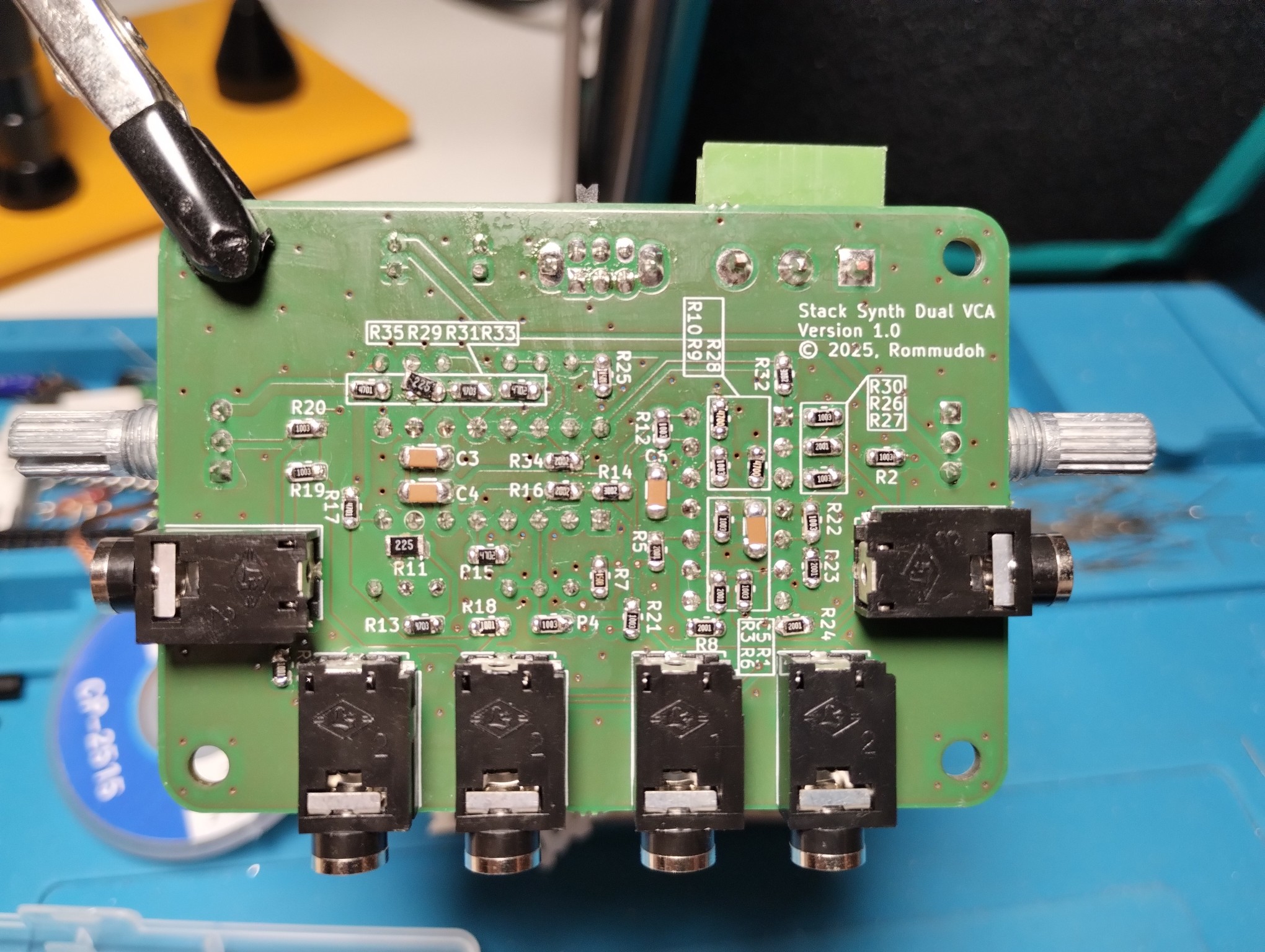
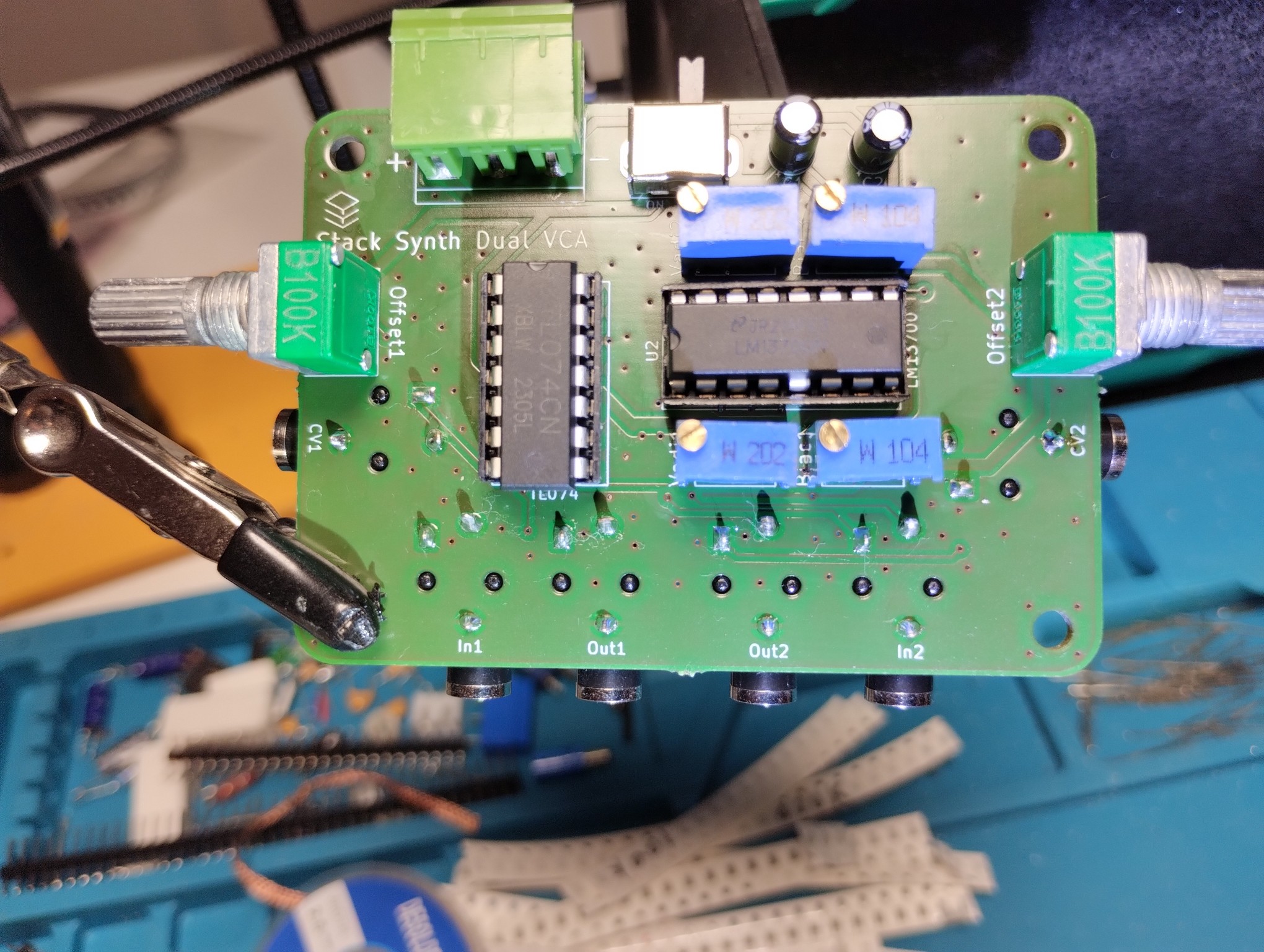
Finished #soldering another #StackSynth #diysynth module, an important one: the #VCA - together with the ADSR, it makes the output sound much better.
Again, boards were manufactured by @aislerhq and they look nice.
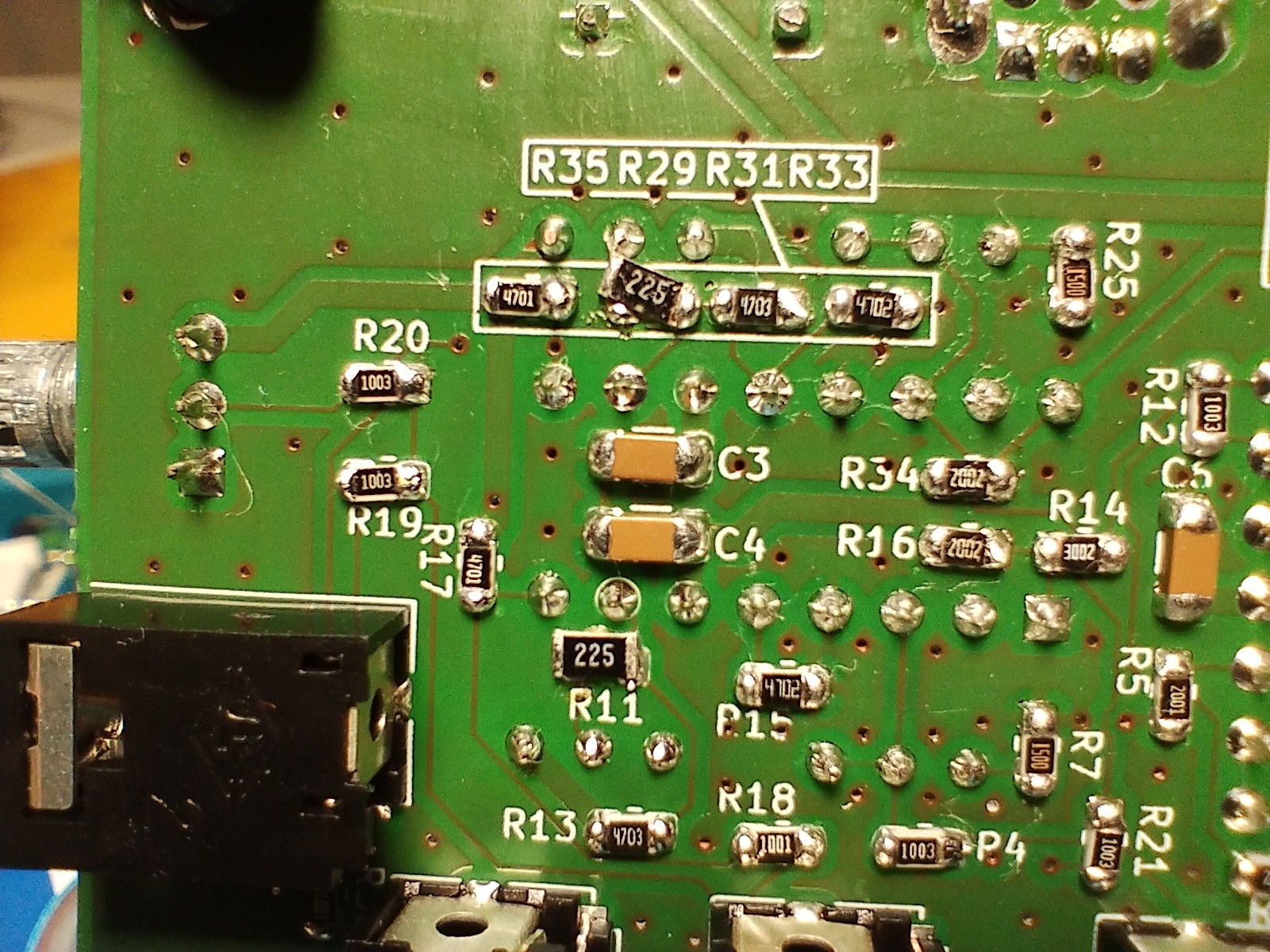
I noticed that I didn't have any 2MΩ 0805 #SMD resistors, but found a couple of larger 1206 2.2MΩ ones in my recycle bin. They don't fit perfectly, but should do until I have the proper ones.
#synthesizer #LM13700 #TL074
#vca
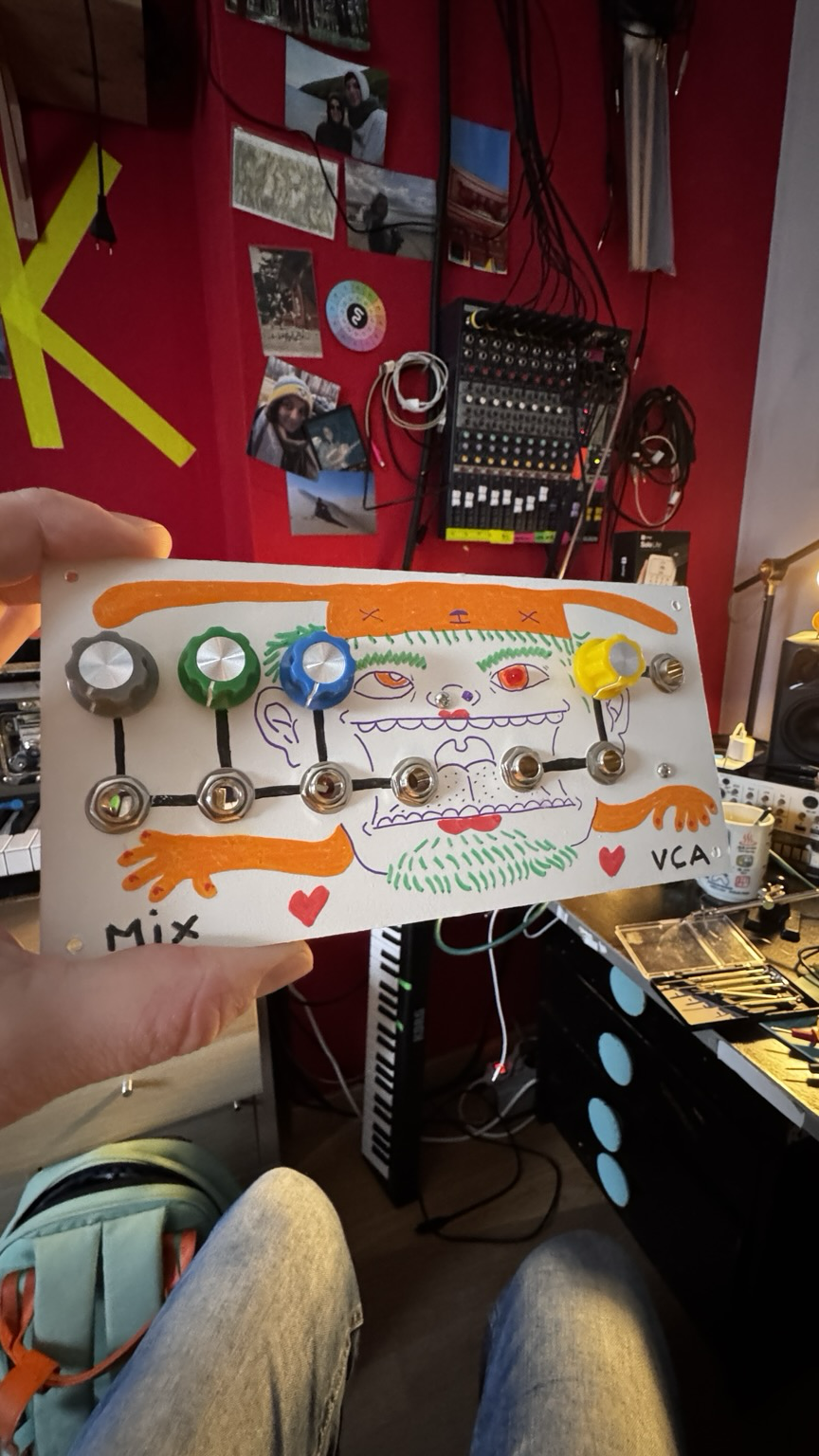
Et hop ! Un nouveau module pour mon synthétiseur modulaire !
Tout simplement un mixer et un vca, 2 en 1, ce qui me permettra de faire un petit peu de place 🩷
Merci à mon ingé-son Tristan pour les beaux dessins !
#diy #modularsynth #vca
Palette patch using Pamela’s workout PRO @busycircuits , bass done with @intellijel dixie2+ Polaris filter both FM micro trigged and chorus FX. Pad and drum loop managed with the sound force samples II. Reverb with Make Noise erbeverb. Enveloppes Quadrax
#intellijel #eurorack #almbusycircuits #pamelaspro #vca #vco #osc
🎄Holiday Eurorack TiNRS Utility set
🎁 NOW 299 EUR 🎁
🎄In our ARDABIL
⛄ Adder + Attenuverter + Offset into Buffered Outputs
⛄ Buffered Output * -1 into Inverted Output
⛄CV (default is Buffered Output) * Audio into VCA Output
🎄and our SWITCH
A double double on-on-on.
🎄and our Rocket Cable set
5 * 10cm cable
5* 42cm cable
2* 91cm cable
🎄and our beloved buttons
#TiNRS #thisisnotrocketscience🚀 #eurorack #modularsynth #VCA #patch #cable #synthesizer
https://www.etsy.com/listing/1837641817/holiday-eurorack-utility-set


New video on transistor matching is out
YouTube: https://youtu.be/qTU7qMQI9Nk
Peertube: https://makertube.net/w/gpyYAaUEPKf8YVse7tm7eo
#synthdiy #synths #transistor #vca #vco #vcf #eurorack
Arteco: nuova versione VCA 2.3 per un nuovo livello di sicurezza: Arteco presenta VCA 2.3, l’ultimo aggiornamento VCA che "ridefinisce" la sicurezza in diversi scenari. Caratterizzato da nuove funzionalita’ e miglioramenti,...
#ArtecoGlobal #sicurezza #VCA #2.3 #deeplearning http://dlvr.it/TG9QsF

One synth I used here is the Roland HS-60. Never heard of it? It was also known as the Roland Synth Plus 60. Still doesn't ring a bell? Remove the speakers, the expression pedal input and give it a different paint job and it becomes the Roland Juno-106. This is my second HS60. I eventually acquired one once I moved to the US, even though I also had an MKS7.
#roland #Juno #juno106 #hs60 #synthesis #synth #synthplus60 #synthesizer #analog #Vcf #Vca #synthesis
Selected kits of DIY Eurorack modules are now available in my store! Check it out at https://store.polykit.rocks
#eurorack #diy #modular #synthdiy #kits #synth #synthesizer #vca #lfo #adsr #envelope
The Eurorack VCA module is out now! There is a blog post on my website and the PCBs are available in my store https://polykit.rocks/vca #eurorack #vca #synthdiy #synthesizer
Wave Displacer off label demo
https://spectra.video/videos/watch/a1d4f7f0-8264-4890-89a2-f1d88b9d92fe
Habe heute eine Stunde mit Benny Adrion gepopcastet. Pls boost: #FCSP #VcA
https://blog.stpauli.social/viva-con-agua-is-coming-home/
The Eurorack VCA PCBs are in production. I'm curious how the front panel will turn out. #eurorack #synthdiy #vca
While being on vacation I started designing the next Eurorack module, it's a discrete VCA. I hope I get some more done. Enjoy the summer! #synthesizer #synthdiy #eurorack #vca
One of my favoured things in #modular #sound #synthesisers is the negative envelope and #inverted #VCA. Inverted VCA is a unique technique in modular that no other instruments can provide. Traditional VCA opens up the volume (or filter) when the key is pressed and we can hear the sound. Inverted VCA closes when key is pressed or signal received and we will not hear the sound until we release the key. It's a good #compositional tool for opening the sound for adding other #instruments or #noises.
Can we all just take a moment to appreciate this parking sign I found in front of #yyc #vca #vetclinic today?
With all my posting about the antics of my newly adopted nutcase, I needed to see this.

Simple DIY Electronic Music Projectsdiyelectromusic.wordpress.com@diyelectromusic.wordpress.com
2024-05-26In the first part I described the concept and basic design parameters I was looking for and then in Part 2 I looked at the detailed electronic design for a board based on the ESP32 WROOM module I have. In this part I go into detail about the code.
- Part 1 – This introduction and high-level design principles.
- Part 2 – Detailed design of an ESP32 based PCB.
- Part 3 – Software design.
- Part 4 – Mechanical assembly and final use – todo.
Warning! I strongly recommend using old or second hand equipment for your experiments. I am not responsible for any damage to expensive instruments!
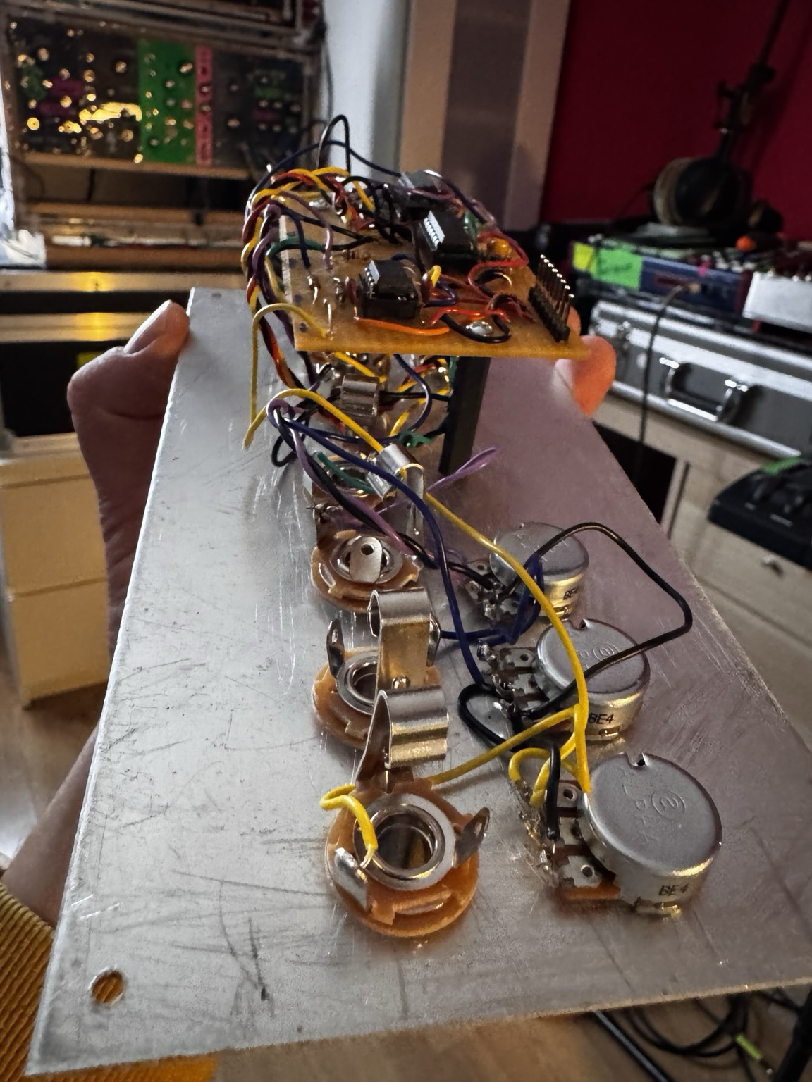
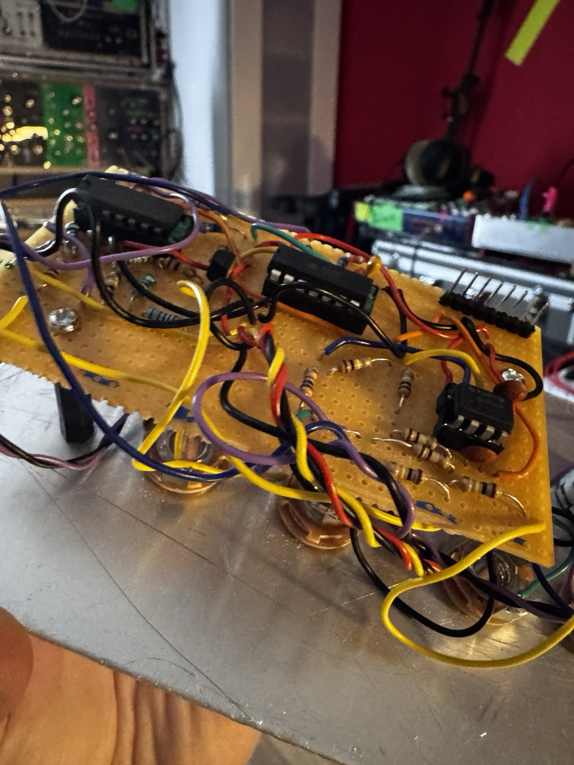
The ESP32 EduMod Hacked Synth Thing
As mentioned in the last part, the principles and code I’m using are taken from these previous posts:
I also now have a built PCB design to make development and testing a lot easier.
Recall the following design choices:
- The two ESP32 DACs are the output for two envelope generators, each driven by four pots (in standard ADSR configuration), a trigger and a gate signal.
- There are ESP32 PWM outputs for two VCOs, each with four waveforms (sine, triangle, saw, square) and an analog input (pot or CV) for frequency and amplitude.
- ESP32 PWM outputs are also used for a LFO with rate and depth analog controls.
- The ESP32 UART is used for MIDI in.
- ESP32 digital IO is used for the envelope GATE and TRIGGER signals, although they are level inverted, i.e. they should be read as active LOW.
Othe points to note:
- There are three “native” analog inputs used for the two VCO pitch and amplitude CVs. All other pots are read via a CD4067 16-way multiplexer.
- Software will determine how the VCO CVs interact with the potentiometers.
- The UART RX pin will be used for MIDI and the UART TX pin will be used for one of the PWM outputs, so there will be no serial port (via USB) for diagnostic output.
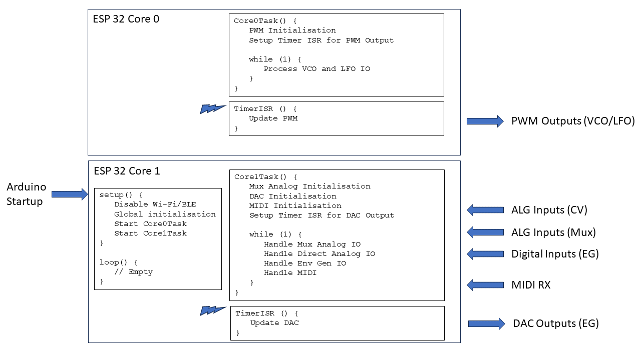
- The ESP32 is a dual core microprocessor, so the aim is to split the functionality across the two cores.
High Level Design
The tasks will be split as follows:
- Core 0:
- Runs the PWM timer at 32,768Hz (although the sample rate will be half this – more on that later).
- Manages the PWM outputs for the two VCOs and the LFO.
- Core 1:
- Runs the EG timer for the DAC at 10,000 Hz.
- Handles the reading of all the IO: “real” analog values; multiplexed analog values; digital IO.
- Handles MIDI.
Multicore ESP32 Arduino
Multicore support for the ESP32 on Arduino is provided using FreeRTOS tasks. For a FreeRTOS application, the default Arduino setup()/loop() will run on core 1. However, once tasks have been created to run on the second core, the default loop is no longer used (I believe).
FreeRTOS enables multitasking on a single CPU (core), each with its own internal priority relative to other tasks. But I’m only using it to start a single task on each core. This is achieved using the xTaskCreatePinnedToCore() function. The last parameter specifies which core to use and the 5th parameter indicates the priority – both are set to “1” as there is only a single task on each core.
The Arduino startup code has thus been reduced to the following:
void core0Entry (void *pvParameters);
TaskHandle_t core0Task;
void core1Entry (void *pvParameters);
TaskHandle_t core1Task;

void setup () {
  xTaskCreatePinnedToCore(core0Entry, "Core 0 Task", 4096, NULL, 1, &core0Task, 0);
  xTaskCreatePinnedToCore(core1Entry, "Core 1 Task", 2048, NULL, 1, &core1Task, 1);
}

void loop () {
  // No main loop here
}

void core0Entry (void *pvParameters) {
  Task0Setup();

  for (;;) {
    Task0Loop();
    vTaskDelay(1); // Allow FreeRTOS IDLE to maintain watchdog
  }
}

void core1Entry (void *pvParameters) {
  Task1Setup();

  for (;;) {
    Task1Loop();
    vTaskDelay(1); // Allow FreeRTOS IDLE to maintain watchdog
  }
}
I’ve simulated the setup()/loop() pattern in each of the task entry points. One thing I quickly found was that if the tasks run with no release of the processor, then FreeRTOS will fail with a watchdog error.
This is why each task includes a vTaskDelay(1) call to allow FreeRTOS to do whatever it needs to do as part of its “idle” processing.
The other thing to be careful of, which would be the same even in a single core application, is that the timers and their timer interrupt routines also allow some general processing time on each core. This will become important further in the discussion.
Task 0: PWM Generation
The essence of Task 0 is the code from ESP32 and PWM. In order to simplify things I’ve created a basic oscillator class as follows:
class COsc {
public:
  COsc ();
  ~COsc (void);

  void Setup (int pwmpin, int wave, bool lfo=false);
  void QuadSetup (int sinpin, int sawpin, int tripin, int squpin);
  void ScanPWM (void);
  void SetFreq (uint16_t freq, uint16_t vol=MAX_VOL);
  void SetMVolts (uint32_t mvolts, uint16_t vol=MAX_VOL);
}
Initially the plan was to have one instance per PWM output. The pin and required waveform is configured as part of the call to the Setup() function.
But then I decided it would be more efficient to utilise the fact that the same index and accumulator can be used to read through each of the four wavetables, so created the idea of a “quad” oscillator. This just requires the four PWM pins to be used to be specified as part of the call to QuadSetup() and eliminates several calls into the ScanPWM function for separate oscillators.
There are two ways to set the oscillator’s frequency output. One is to pass in the frequency directly, the other is to pass in a millivolt reading from a potentiometer based on a 1V/oct scaling. The “zero volts” frequency is preset to be 65.406Hz, i.e. C2.
The frequency is derived from the millivolt reading using the following:
void COsc::SetMVolts (uint32_t mvolts, uint16_t vol) {
  // Set frequency according to Volt/Oct scaling
  //   Freq = baseFreq * 2 ^ (voltage)
  //
  float freq = FREQ_0V * (powf (2.0, ((float)mvolts)/1000.0));
  int f = (int)freq;
  SetFreq(f, vol);
}
With the default settings this class can be used for both VCO and LFO, but the lowest frequency for the LFO was just 1Hz. Consequently, I’ve added the option to specify a “LFO” setting as part of the single oscillator Setup() function. If enabled, then the oscillator runs 10x slower than default. This allows for frequencies down to 0.1Hz, but does mean that the frequency or millivolt parameters are now treated as being 10 times smaller than their values would imply.
Note when MIDI is added into the mix, I just use the NoteOn message to change the base frequency used for the oscillators.
The ScanPWM() function is designed to be called from the interrupt routine running at the sample rate.
The oscillators are thus created as two Quad oscillators (one per VCO) and two single oscillators for the dual waveforms of the LFO:
#define OSC_VCO1 0
#define OSC_VCO2 1
#define OSC_LFO1 2
#define OSC_LFO2 3
#define NUM_OSC 4
COsc *pOsc[NUM_OSC];
int pwmpins[NUM_OSC][4] = {
  {17,18,5,19},
  {21,22,1,23},
  {16,0,0,0},
  {13,0,0,0}
};
int oscwaves[NUM_OSC] = {
  OSC_WAVES,  // VCO 1 (quad)
  OSC_WAVES,  // VCO 2 (quad)
  OSC_TRI,    // LFO
  OSC_SAW
};

void oscSetup() {
  for (int i=0; i<NUM_OSC; i++) {
    pOsc[i] = new COsc();
    if (oscwaves[i] == OSC_WAVES) {
      // This is a quad oscillator
      pOsc[i]->QuadSetup (pwmpins[i][0], pwmpins[i][1], pwmpins[i][2], pwmpins[i][3]);
    } else {
      // A single oscillator - these are the LFOs
      pOsc[i]->Setup (pwmpins[i][0], oscwaves[i], true);
    }
  }
}
The timer configuration for Task 0 is as follows:
#define TIMER_FREQ  10000000  // 1MHz * 10 (0.1uS)
#define TIMER_RATE  305       // 30.5 uS * 10

Task0Timer = timerBegin(TIMER_FREQ);
timerAttachInterrupt(Task0Timer, &Task0TimerIsr);
timerAlarm(Task0Timer, TIMER_RATE, true, 0);
This generates a timer interrupt running at 32,768Hz from a 10MHz timer
However, servicing 10 PWM outputs means that there is no time remaining once interrupt processing is complete for any other operations. Consequently, I set things up so that the PWM outputs are updated in two blocks of 5, meaning that the effective sample rate for PWM purposes is actually now 16,384Hz:
int toggle0;
void ARDUINO_ISR_ATTR Task0TimerIsr (void) {
  toggle0 = !toggle0;
  if (toggle0) {
    pOsc[OSC_VCO1]->ScanPWM();
    pOsc[OSC_LFO1]->ScanPWM();
  } else {
    pOsc[OSC_VCO2]->ScanPWM();
    pOsc[OSC_LFO2]->ScanPWM();
  }
}
The main Task 0 Loop just pulls in the analog IO values that have been read as part of the processing of Task 1. These values are then used to set the frequencies of each VCO and the LFO.
Task 0: VCO Control
The VCO potentiometers and CV inputs have to be combined to determine the frequency and amplitude of the PWM signal.
In terms of amplitude, I’ve chosen to use the maximum of the pot or CV input to set the amplitude of VCO 1. Note that VCO 2 has no amplitude input, although with hindsight, I could have included a pot even though I’ve run out of GPIO pins for a CV input.
This means that the pot has to be turned fully “off” for the CV to become significant.
In terms of setting the frequencies, I initially thought about some kind of frequency modulation, which would have been good for linking the two VCOs together, but then decided actually I wanted a more straight forward relationship between pot and CV to allow the use of the LFO or the EGs for pitch. The result is going for a simple summation of the two inputs which gives a 3 octave range (started at C2) for each of the CV and pot, but when combined could give up to a 6 octave spread of frequencies.
When MIDI is enabled, that will set the base frequency for the summation rather than defaulting to C2. This will set the base for both VCOs, so the pots/CVs could be used for a detuning style effect.
Note: Due to the issues with the choice of pins for the inputs, the base level of the CV input for VCO2 is floating at around 300-600mV. The default (unconnected) configuration introduces an element of detuning. If the CV inputs are not wanted, then it is recommended to connect them to GND to eliminate this effect.
The result of taking this approach, combined with the frequency of scanning the inputs, means that if one VCO is used to set the frequency for the other, then it probably won’t track the voltages accurately enough for a smooth modulation. But it does generation quite a wacky “sample and hold” style aliasing effect, which actually I quite like.
I could try to do something about that, but I think in reality this is a use-case where a purely analog VCO can be added via breadboard as part of the experimentation which can be driven from the PWM VCOs – that should enable a number of possibilities for more complex oscillator modulation.
There is also some clipping at higher LFO frequencies if used as the amplitude input. This needs to be investigated to see if that is a bug in the code or handling of the CV somehow.
It is possible that this, and the aliasing of pitch, is a consequence of the frequency of scanning the analog inputs or the speed of the analogRead() function itself – it’s pretty slow. Some investigation is required to experiment with changing the frequency of the reading or rewriting to use the ESP32 API rather than the (slower) Arduino analogRead() function (more on that later).
Task 1: IO Scanning
All the IO is scanned as part of Task 1’s main processing loop. This has to cover the following:
- Real analog values from the inputs corresponding to the VCO CVs.
- Multiplexed analog values for all the pots for the VCOs, LFO and two EGs.
- Digital IO for the EG gates and triggers.
I started off reading the “real” analog IO associated with the VCOs in task 0, but found that it just wasn’t being scanned frequently enough to function in any useful manner. Also, the calls to analogRead() incur some kind of processing overhead that appears to interfere with the timing of the PWM timer interrupt, leaving “blips” in the output.
I started to think about writing a FastAnalogRead() function to use the ESP32 SDK directly rather than the Arduino analogRead() function, but before doing that moved all the IO processing over to Task 1. It turns out that this seems to work adequately so if I’ve not done that at present.
But one consequence of this chain of thought is that I now have two sets of functions performing my own analog IO reading:
- MuxAnalogRead()
- FastAnalogRead()
Which both perform in very similar ways. I’ll describe the API for MuxAnalogRead(), but the same principles were used for FastAnalogRead() too.
void MuxSetup(void);
void MuxLoop(bool bVoltageReading=false);
void MuxLoopSingle (uint8_t pot, bool bVoltageReading=false);
uint16_t MuxAnalogRead (uint8_t pot);
uint32_t MuxAnalogReadMilliVolts (uint8_t pot);
The two Loop functions are designed to perform the actual reading from the hardware. Loop will read all known values in a single scan. LoopSingle() will read a single pot.
The functions MuxAnalogRead() and MuxAnalogReadMilliVolts() are used to retrieve the previously read values.
Scanning is performed using either the standard analogRead() or the ESP32 API function analogReadMilliVolts(). This is why a bVoltageReading parameter is required as part of the two Loop functions. It would be possible to calculate one from the other for every reading, but I’ve opted not to do that in order to keep the calculations required as part of a read as minimal as possible.
This allows the scanning of the hardware to happen on one core (in Task 1 in this case) yet be read from the other (Task 0).
Digital IO processing just requires monitoring the trigger and gate inputs for a HIGH->LOW transition and call the appropriate triggerADSR() or gateADSR() functions as required, although there is a bit more logic required to work in the MIDI input.
The actually scanning of IO is split over the different scans of the Task Loop as follows:
#define S_MUX (NUM_MUX_POTS-1)
#define S_FASTIO (S_MUX+1)
#define S_DIGIO  (S_FASTIO+1)
#define S_ALGIO  (S_DIGIO+1)
#define S_MIDI   (S_ALGIO+1)
#define S_LAST   (S_MIDI+1)
int taskState;

void Task1Loop(void)
{
  if (taskState <= S_MUX) {
    // Read each MUX pot in turn
    switch (taskState) {
      case 5: // VCO 1 CV
      case 7: // VCO 2 CV
        // These are read in millivolts...
        MuxLoopSingle(taskState, true);
        break;
      default:
        // These are read as 12-bit raw 0..4095
        MuxLoopSingle(taskState, false);
        break;
    }
  }
  else if (taskState == S_FASTIO) {
    Task1FastAlgIOLoop();
  }
  else if (taskState == S_DIGIO) {
    Task1DigIOLoop();
  }
  else if (taskState == S_ALGIO) {
    Task1AlgIOLoop();
  }
  else if (taskState == S_MIDI) {
    Task1MIDILoop();
  }
  else {
    taskState = S_LAST;
  }
  taskState++;
  if (taskState >= S_LAST) {
    taskState = 0;
  }
}
Task 1: Envelope Generation
The core of the envelope generation code is from ESP32 DAC Envelope Generator, but once again the code has been refactored into a class as follows:
class CEnv {
public:
  CEnv ();
  ~CEnv (void);

  void setADSR (int eg_a, int eg_d, int eg_s, int eg_r);
  uint8_t nextADSR (void);
  void triggerADSR (void);
  void gateADSR (bool gateOn);
  void dumpADSR (void);
}
One change is setting the ADSR parameters in a single call. The values are assumed to be potentiometer readings in the range 0..4095.
Two envelope generators are created by Task 1:
CEnv *pEnv[NUM_ENV];

void envSetup() {
  for (int i=0; i<NUM_ENV; i++) {
    pEnv[i] = new CEnv();
  }
}
The nextADSR() function has to be called for each envelope generator from the timer interrupt routine.
The timer configuration for Task 1 is as follows:
#define TIMER_FREQ  100000  // 100kHz (0.01mS)
#define TIMER_RATE  10      // 0.1mS

Task1Timer = timerBegin(TIMER_FREQ);
timerAttachInterrupt(Task1Timer, &Task1TimerIsr);
timerAlarm(Task1Timer, TIMER_RATE, true, 0);
This generates a 10kHz sample rate for the EGs from a 100kHz timer signal.
Task 1: MIDI
I’m using the standard Arduino MIDI library. There are a couple of points to note however:
- MIDI will set the TRIGGER and GATE according to the reception of NoteOn and NoteOff messages.
- I will need to keep track of which note is playing so that overlapping NoteOn/NoteOff messages don’t confuse the GATE handling.
- As I’m reusing the TX pin as a PWM output, PWM initialisation must happen after MIDI initialisation, otherwise MIDI will assume the use of both RX and TX.
- Serial MIDI by default implements “software MIDI THRU” so this needs to be disabled using setThruOff().
- MIDI will set the base frequency used for the VCO controls, so the pot and CV will add to the MIDI frequency.
It isn’t clear what should happen with regards to frequency on NoteOff. Here are some options:
- Reset back to default base frequency on NoteOff (the “0V” state), but this has the disadvantage that the frequency changes as soon as the gate signal initiates the Release state of the ADSR.
- Wait until the envelope has finished the Release stage to reset the base frequency. This seems sensible when using the EGs, but has the disadvantage that when just using MIDI to set pitch, it will not revert back immediately on “key up” – it will only revert back when the envelope is complete, which is confusing if the EG is not being used.
- Don’t reset the base frequency, this means the note will continue on the last used frequency until a new note is played.
I’ve opted not to reset the base frequency on the basis of: if MIDI on/off handling is required, then it will probably be using envelopes anyway. If not, then having only MIDI on setting a sustained frequency sort of makes more sense to me.
Closing Thoughts
The code will continue to evolve as I keep tinkering with it, but the current state can be found in the GitHub repository for the project here: https://github.com/diyelectromusic/ESP32EduModHackThing
There are still a few quirks and things I might continue to investigate and possibly optimise. Specifically:
- The performance for reading the “real” analog CVs for the VCOs.
- The frequency handling with respect to MIDI.
But in general I think it is starting to get pretty usable.
Kevin
https://diyelectromusic.wordpress.com/2024/05/26/educational-diy-synth-thing-part-3/
#adsr #define #envelopeGenerator #esp32 #lfo #oscillator #vca #vco
Simple DIY Electronic Music Projectsdiyelectromusic.wordpress.com@diyelectromusic.wordpress.com
2024-04-20Following on the back of my ESP32 DAC Envelope Generator and in particular my note at the start that it was essentially the code algorithm and none of the electronics that might make it useful, I started to try to find the simplest possible circuit that Just Might Work as a voltage controlled amplifier (VCA) for demonstration purposes. It turned out to be quite a “rabbit hole”. This post details where I ended up.
But first, just to be clear, I’ll repeat my warning from last time – don’t hook this up to anything else unless you really know what you are doing (unlike me). This is my fumbling around with a little knowledge, largely being “dangerous”, based on random circuits I’ve found online. If that isn’t enough to scare you off, I’m not sure what is…
Warning! I strongly recommend using old or second hand equipment for your experiments. I am not responsible for any damage to expensive instruments!
If you are new to electronics and microcontrollers, see the Getting Started pages.
Introduction
I’m after a voltage-controlled amplifier (VCA) that can be controlled with my 0-3V3 signal and that could be used to shape an audio signal. This can be thought of as a “black box” with an audio input and output and a control voltage.
But of course there are a large number of considerations if one is to do this properly.
So naturally I threw all that out the window and started searching online for “simple VCA circuit” to see what comes back.
I’m not after any specific quality of VCA, I just want to see the art of the possible with regards to fewest components, simplest design, and useful demonstration of the envelope generator working.
The designs I’ve found can be categorised largely as follows:
- Opto-electronic based designs – e.g. optoisolators, vacrols or similar.
- Transistor based designs – often paired with diodes.
- Op-amp and amplifier based designs – these are starting to get more complex, but seem to produce some pretty usable designs from what I can see.
- Dedicated chips – e.g. the AS3330, AS3360 and compatible devices.
I’d suggest that I’ve probably listed these in order of simplicity (simplest first) which also seems to be inversely proportional to quality of output (that is, the best is last).
Opto-electronic Based Designs
These had instant appeal to me as they appear to be pretty simple on the face of things. Essentially the control voltage modulates the light emitting side of an optoelectronic device such as an LED; which in turn modulates a light sensing side which controls the level of an audio signal.
Here is one of the simplest designs I found using an optoisolator: https://www.reddit.com/r/synthdiy/comments/lreytp/simple_vca_in_eurorack_format_on_stripboard/
This includes a circuit for an LED to indicate activity, which I wasn’t so bothered about, so I’ve simplified it further to the following:
This is about the simplest thing I’ve found and it does kind of work to a degree. I found myself with some cheap optoisolators so used those. The key points to consider for this:
- The resistor on the CV input has to limit the current through the optoisolator’s LED.
- The optoisolator’s LED will only start conducting when the CV input reaches the LED’s forward voltage.
I used a PC817 and PC814. The only difference as far as I can see is that the 814 allows for AC operation, incorporating two diodes in the input side.
For both, the forward voltage of the LED is nominally 1.2-1.4V, which is almost half the CV level! This means that attempting to use the envelope generator “as is” significantly reduces the effectiveness of the levels.
There might be a way to bias the input signal, but I’ve not found a simple way in electronics to do this. Ideally, the voltage range for the input would end up in the region of 1.2-4.5V (i.e. up to 3V3+1.2V), but I don’t know how to do that myself for a slow changing voltage like this – at least not without getting more complicated (and probably involving OpAmps) I must admit to being seriously tempted to give this idea a go as suggested by “Chip” on Mastodon as a very crude possibility, but I’m not sure how the DAC would like that…
Another option might be some simple amplification so that the voltage drop across the LED is a smaller fraction of the whole range.
One simple way to avoid the additional electronics is to introduce an offset in the code so that the output of the DAC is in the range 1.2-3.3V, so that is what I’ve done for now and that seems to work pretty well.
On the oscilloscope trace below, I have the output to a 8Ω speaker. We can see that it is ridiculously noisy… but it does work! It sounds a lot better than it looks and there is no filtering or processing going on other than what is shown in the circuit above.
Using a minimum ATTACK_LEVEL of 70 seems to ensure there is little audio leaking, but it is possible to hear where the voltage drops below the forward voltage of the LED – there is a slight blip. In the photo below it is clear to see the non-linearity of the response (top) compared to the control voltage (bottom), especially in the rising ATTACK stage.
The audio in this case is the ESP32 generating a 440Hz tone using the Arduino tone() function, so it is a 0-3V3 square wave being generated.
Most designs using optoelectronics tend to use a VACTROL. This is effectively an LED glued to a LDR in a sealed enclosure. They can be bought or made (apparently VACTROL is a brand name, but that is what everyone calls them).
Here are some circuits and tutorials using a VACTROL as a VCA that look quite interesting and probably worth following up:
- Kirstian Blastol’s Modular in a Week video “Vactrol VCAs and CV Attenuators”. This video shows how to build your own vactrols using a variety of methods. His “Schematic_Vactrol” is essentially the same circuit as shown above for the optoisolator…
- Benjie Jiao’s “Passive Vactrol VCA” which is a very similar circuit again, described as a “low pass gate”.
- “Voltage to resistance” from thesquarewaveparade (search for thesquarewaveparade VtoR.jpg) has a range of increasingly complex, but still relatively straightforward to understand circuits for a voltage-controlled resistance.
But the best discussion on how to make best use of a Vactrol, and hence by inference (by me) probably also an optoisolator can be found here:
- Rich Holme’s “How to Vactrol”.
I just used exactly the same circuit as for my optoisolator, but the Vactrol I’m using seems to have a larger forward voltage. It is marked VTL5C9, but I’m not sure it’s an “official” Xvive one – but if it is, then the datasheet states a forward voltage of 2.5V which is rather a lot when my control voltage tops out at 3.3V!
To be any use at all, I’ve had to set the minimum ATTACK_LEVEL to 110 which has essentially halved the resolution. But once again, it does work for some definition of “work”.
The longer lead is the anode for the LED side – then I’ve just used it in place of the optoisolator.
Transistor Based Designs
A number of simple VCA designs use a single transistor or a transistor and a diode. I found this one being discussed online so gave that a go:
As far as I can see this is sort of “reversed” in the sense that rather than the control voltage controlling the audio, to me it looks like the audio is controlling the control voltage signal… the end result is still audio only when the control voltage enables it though.
I didn’t have a BC549B transistor, which I believe is a common low-noise NPN transistor, so I used a 2N3904 instead. Note that the pin assignments are different between the two!
One of the advantages of this design appears to be good tracking of the envelope as can be seen below. The actual output level isn’t very high though – the blue scale is 200mV compared to the yellow’s 1V below. I suspect that is a result of attempting to drive the 8Ω speaker directly. I guess this would need to go into some kind of buffer or amplifier stage with some sensible impedance matching at the very least, to be particularly useful.
There is some discussion of this circuit here: https://www.modwiggler.com/forum/viewtopic.php?t=168810. I believe it is only working in the simple case shown above as the audio signal is biased to a 0-3.3V signal rather than a +/- signal.
A bit further down in the linked thread there is an example of how to cope with an unbiased input audio signal by adding a DC bias to the transistor base, so I tried a variant of that as follows:
As I’m using a 3V3 control voltage, I’ve used 680kΩ and 100kΩ to bias the transistor at around 420mV. A coupling capacitor removes any existing DC bias to the audio signal prior to feeding it in.
The final signal at the loudspeaker is pretty low as before, but if I take the output from just before C1 it is looking pretty good to me although we can see the output is still positive only.
Once again, the trick now would be to buffer or set up the load on this signal to preserve it as an actual audio out.
This is pretty crude, but then the discussions implied nothing less. But for a handful of largely passive components, this does seem to show some promise.
For a proper discussion on the workings of transistor based VCAs, I can recommend:
- Moritz Klein’s “Designing a classic transistor-VCA from scratch”.
- AudioPhool’s “Single Transistor Voltage Controlled Amplifier (VCA)”.
OpAmp Output Buffer
For completeness I briefly experimented with adding a LM358 OpAmp based buffer (or “voltage follower”) circuit as follows:
This is connected instead of the speaker in the previous circuit so the input is coming from the right hand side of the 100nF capacitor, so the input is unbiased. But the OpAmp is running from 5V and there are two resistors on the input which adds a 2.5V bias.
The output is pretty good, but I can see the top of the envelope being clipped in the positive direction. I’m not entirely sure why – I thought powering it from 5V (rather than 3V3) would give enough headroom for a decent signal, but maybe not.
Also my limited electronics knowledge is failing me in understanding how the signal shown above (measured at the collector output for the transistor) becomes the signal shown below (measured after the final capacitor in the buffer circuit).
Once again it is probably something to do with my lack of understanding of output impedance and related topics.
It might work better with a LMV358 rather than a LM358 as apparently the LMV version runs better at lower voltages with output much closer to the power rails (“rail to rail”). It might also be possible to adjust the bias resistors and re-align the signals somehow…
Other Transistor Circuits
I also found a couple of circuits where the control voltage is fed into the base of the transistor to control the audio passing through it in a more “traditional” (or at least, “expected” by me) manner. But I wasn’t really able to get them working, so I didn’t take those any further. One I never actually tried as the LMNC “painfully simple VCA” which is essentially just a diode and transistor.
I also found a circuit describing a “swing VCA” but again my initial experiments didn’t seem to give me anything useful, so I’ve largely ignored those too.
OpAmps and Amplifier Based Designs
In one of the discussions I found talk of a TDA7052A in use as a VCA. It was posted by elektrouwe in the discussion here: https://electro-music.com/forum/topic-63383.html&postorder=asc. Further on in the discussion was another circuit, posted by Hammer.
The original TDA7052 is a 1W mono audio amplifier apparently designed for battery led operations and to be powered by 3-18V. The TDA7052A is an upgrade that adds DC voltage volume control, but I believe the power requirements have increased slightly to requiring a 4.5-18V source.
A good discussion for how to use them can be found here: https://electro-dan.co.uk/electronics/tda7052.aspx.
In particular, note that elektrouwe states:
“TDA7052A has a gain of ~ 56x, which means Vin should be in the 100mV range, otherwise you need an input voltage divider. You MUST use an input coupling cap., because the chip generates an internal DC bias voltage.“
Pretty much every other example circuit I’ve seen shows the two outputs (pin 5 and 8) connected directly to a 8Ω loudspeaker, but the design above is only using one of the outputs. The two outputs apparently provide an inverting and non-inverting output option.
Here are some key points that might be relevant to its use as a VCA (from the “TDA7052A/AT: 1 W BTL mono audio amplifier with DC volume control” datasheet, dated July 1994, sometimes braded Philips, sometimes NXP):
- “The maximum gain of the amplifier is fixed at 35.5 dB.”
- “The DC volume control stage has a logarithmic control characteristic.”
- “The total gain can be controlled from 35.5 dB to −44 dB.”
- “If the DC volume control voltage is below 0.3 V, the device switches to the mute mode.”
- Positive supply voltage range: 4.5V to 18V.
From the graphs in the datasheet (shown below), the response appears pretty linear when the DC volume control voltage is between 0.4 and 1.2V.
So I think the summary is that to use this as a VCA then the control voltage needs scaling to the 0.4-1.2V range (or thereabouts) and the input signal needs to allow for a maximum 35.5dB gain at the high end of that range. The article I linked to earlier describes the original TDA7052’s 39dB gain as equivalent to a voltage gain of 90 times, so to keep within the 0-5V presumed output range, that would require an input audio signal in the 50-100mV range.
I took an approach that largely used elements of each circuit. From here, we are told:
“The DC volume control is at pin 4. The TDA7052A produces a voltage of around +1.125V at this pin, as well using the current at this pin as a volume reference.”
So I thought the approach of using a PNP transistor to modulate that according to the control voltage was probably the way to go.
To get my CV (which is in the 0-3.3V range) down to 0-1.2V I used a voltage divider of a 2MΩ and 1MΩ resistor dropping the range down to approx 0-1.2V. To keep the audio signal within a sensible range to allow for the full gain, I used another voltage divider, this time using a 1MΩ and 100kΩ resistor dropping my 0-3.3V test signal down to around 0-300mV, which is perhaps still a little high, but it was fine for a test. Any final circuit may have to account for a line-level audio input (probably) so will need to be adjusted accordingly.
Note, from my experiments, the audio input (pin 2) seems to be internally biased at around 2.6V. This was with either a 3V3 VCC or 5V VCC.
So here are the components used:
- 1x TDA5072A
- 1x BC557 PNP transistor
- 1x 1KΩ resistor
- 2x 1MΩ resistors
- 1x 2MΩ resistor
- 2x 1uF electrolytic capacitors
- 1x 10uF electrolytic capacitor
The circuit is designed for a 0-3.3V CV input and is powered from a 0-5V supply.
And here is my test circuit:
And this seems to work fairly well. In the following trace (I’ve swapped the traces over – blue is now the CV and yellow the output), we can see the effect of both the logarithmic response of the DC volume control of the TDA5072A and possibly some maxing out of the volume when at full (I’m not sure tbh).
But it certainly sounds convincing to me and is perhaps the most promising solution so far.
The LM13700 Transconductance Amplifier
The LM13700 appears to be a massively useful circuit in synthesizer designs! I’ve found it used in at least three designs online and it has a chapter of its own in “Make: Analog Synthesizers” by Ray Wilson.
I’ve not got any at the moment, but here are links to the designs and some further discussions about it:
- https://benjiaomodular.com/post/2021-12-17-lm13700-vca/
- https://electricdruid.net/design-a-eurorack-vintage-vca-with-the-lm13700/
- https://www.davidhaillant.com/simple-vca/
This will be one to come back to.
Closing Thoughts
This was a bit of a diversion, and really I was after the cheapest, simplest, VCA I could manage to build.
I really like the simplicity of the optoisolator/vactrol approach, and for higher signal voltages I can see that it would work well, but for 0-3.3V signals the non-linearity from the use of the LED is just too great. If I can find a simple way to add ~1.5V to the signal then this would probably work pretty well.
The transistor designs were very encouraging, but I suspect I’d really need a little more electronics knowledge to be able to sensibly use them in a circuit.
The TDA7052 is the easiest for me to understand at present, but I would like to return to the topic if I managed to get hold of some LM13700 equivalent devices at some point.
One group I never mentioned is dedicated VCA/EG chips, like the AS3330/33360 or the CEM2164. Again this is probably a subject to return to at some point, but I’m getting quite well past simple, cheap, lo-fi at that point – these are used in proper modular synth designs.
Just a reminder – none of these circuits have any input protection, there is no buffering, and no thoughts of impedance – they are literally the bare bones that might have a hope of kind of working (if at all). They are just part of me learning how some of these things work.
They are not intended for any real use and certainly not for use with any equipment that isn’t disposable.
Kevin
https://diyelectromusic.wordpress.com/2024/04/20/esp32-dac-envelope-generator-part-2/
#envelopeGenerator #esp32 #lm13700 #optoisolator #tda5072 #vactrol #vca
The best budget effects pedals for electronic music production https://www.gearnews.com/the-best-budget-effects-pedals-for-electronic-music-production/ #PurchaseAdvisor #buyer'sguide #effectspedal #compressor #distortion #Modulation #sidechain #Eurorack #parallel #Columns #effects #Flanger #Modular #chorus #filter #reverb #Update #delay #Pedal #Video #VCA #FX
Client Info
Server: https://mastodon.social
Version: 2025.04
Repository: https://github.com/cyevgeniy/lmst