#oscillator

2025-05-18

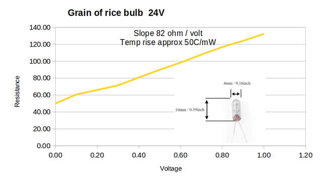
I'm playing with a Wien bridge sinewave oscillator and just characterised a small bulb to stabilise it. I was really surprised how sensitive the resistance was to applied voltage. I'm going to set the feedback resistor to 180R so everything should stabilise around 5V p-p. The opamp will peak at 10mA to drive it so everything should be fine.

The tungsten filament appears to have a temperature coefficient of 50C/mW so it will be running at around 200C.

#electronics #oscillator

Graph of resistance against voltage for a 4mm 24V grain of rice bulb. The voltage range is from 0V to 1V with the resistance going from 50 to 132 ohms. 
The subtitle states the resistance slope is 82 ohms/volt with a temp rise of approx 50C/mW.
STM32Worldstm32world
2025-01-19

STM32 Tutorial #31 - Measuring LSI Frequency (for Watchdog)
In an earlier video (Tutorial video #29) we worked with the Independent Watchdog (IWDG) and were slightly confused about the timing. In this video we will verify the results we found but actually measuring the frequency of the LSI (Low Speed Internal oscillator). It is incredible important to understand the implications of the LSI drift.

youtube.com/watch?v=4lfsBK5ahWA

Simple DIY Electronic Music Projectsdiyelectromusic.com@diyelectromusic.com
2025-01-05

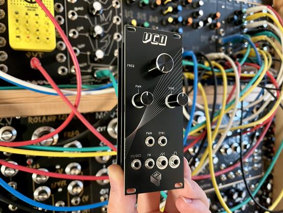
EuroRack 6HP Arduino Mozzi Module – Basic VCO

This is the first project based on my EuroRack 6HP Arduino Mozzi Module. It is loosely based on HAGIWO’s Arduino Mozzi VCO Module.

https://makertube.net/w/hnocMAhYkajd8nX2vwuR2u

Warning! I strongly recommend using old or second hand equipment for your experiments.  I am not responsible for any damage to expensive instruments!

These are some previous posts for the main concepts used in this project:

If you are new to Arduino, see the Getting Started pages.

Parts list

The Circuit

This uses the EuroRack 6HP Arduino Mozzi Module with the pots and jacks assigned as shown below.

The four potentiometers control the following:

  • POT 1 – OSC 1 core frequency offset (from V/Oct CV).
  • POT 2 – OSC 2 frequency ratio OSC1.
  • POT 3 – Waveform for both oscillators: sine, triangle, saw, square.
  • POT 4 – Octave: 1 lower, normal, 1 higher, 2 higher.

There are three CV inputs:

  • V/Octave pitch.
  • OSC1 vs OSC2 gain.
  • Pitch modulation.

The Code

The code is inspired by that of HAGIWO’s Mozzi VCO, in that I’m using Mozzi with two oscillators, with multiple waveforms, and I’m using HAGIWO’s gain profile for CV. But I’ve added a few extras and have rewritten the core Mozzi code to hopefully be a little more optimal.

The main V/Oct calculation has to happen every scan and HAGIWO uses a look-up table in PROGMEM for the fractional voltages that correspond to each value of the ADC and then uses those in the standard Volts to frequency equation:

Freq = BaseFreq . 2^CV

For a 10-bit resolution (the resolution of the Arduino ADCs) this requires 1024 values across the whole 5V range. That equates to 4.8828mV per step (5/1024) and as full octave of 12 steps is 1V that equates to 83.3mV per semitone.

The various CV recommendations I’ve seen suggest using a BaseFreq equal to C4, which is 261.6256 Hz in the calculation unless it is for a LFO or clock in which case a BaseFreq of 2Hz is recommended – which corresponds to 120 bpm if used for a clock. The BaseFreq is the frequency used for 0V. Many analog synths will accept negative voltages to go lower, but as this is an Arduino it only supports 0V to 5V.

HAGIWO uses a table of float values and uses floating point arithmetic to work out the frequency. I’ve opted to use fixed point arithmetic and also rather than store the CV “step” values in the table have pre-calculated the whole 2^CV for each step.

Here is some Arduino code that will output the required look-up table values. My full version will first output the individual voltage steps to 6 decimal places; then for the float version of 2^CV; and finally for the fixed point 16.16 equivalent – that is 16 bits for the integer part and a fixed 16 bits for the binary equivalent of the decimal part.

The code below just does the last part. This is using the FixMath library which was written for use with Mozzi (more here).

#include <FixMath.h>  // Designed for use with Mozzi

int res = 10; // 10-bit resolution
float maxv = 5.0; // Max voltage

void setup() {
Serial.begin(9600);

int max = (1<<res) - 1;
float cvstep = maxv / ((float)max+1.0);

Serial.print("\n\n");
Serial.print("Resolution=");
Serial.print(res);
Serial.print(" bits (0 to ");
Serial.print(max);
Serial.print(")\tV/step=");
Serial.print(cvstep,6);
Serial.print("\n");

float cv = 0.0;
for (int i=0; i<=max; i++) {
if (i%16 == 0) {
Serial.print("\n");
}
float freqpow = pow(2, cv);
UFix<16, 16> q16n16fp = freqpow;
Serial.print("0x");
Serial.print(q16n16fp.asRaw(), HEX);
Serial.print(",");
cv += cvstep;
}
}

void loop() {}

I’ve used this to create the q16n16 version of the 1024 values required to calculate the frequency for each of the 0..1023 values that the 1V/Oct analog input could provide, covering the full 5V range. This is stored in the header file v2voct.h that is part of the code.

This does mean that any calculation of frequency must be done using the FixMath 16.16 values, for example:

UFix<16,16> q16n16potfreq = mozziAnalogRead(POT1);

This code takes the unsigned integer value (0 to 1023) from mozziAnalogRead and automatically turns it into a 16.16 fixed point format value in variable q16n16potfreq – note that in each case the decimal part will be zero as the starting point is an integer between 0 and 1023.

When reading values in from the look-up table, they have to be pulled in “raw” as they are already in the 16.16 format. But as Arduino doesn’t know anything about this format, they have been declared as uint32_t values in the PROGMEM structure, but then need to be read back out and treated as 16.16 values as show below.

#define CVSTEPS 1024
static const uint32_t q16n16fp [CVSTEPS] PROGMEM = {
0x10000,0x100DE,0x101BD,0x1029C,
...
};

UFix<16,16> fpow = UFix<16,16>::fromRaw(pgm_read_dword(&q16n16fp[voct]));

All calculations related to frequencies are performed using 16.16 values. The Mozzi oscillator setFreq function has a version that takes 16.16 values too, making everything actually quite straight forward once you get your head around what its doing.

Other notes on the code:

  • There are two gain values maintained – one for each oscillator. The values used come from another look-up table (that I took from HAGIWO’s original) that allows the CV to pan across from one oscillator to the other. I’m using 7-bit gain values (0..127) so that when the final audio sample is worked out at the end, it should all fit within a 16-bit value give or take.
  • The octave selector changes the octave of both oscillators and is determined by POT 4 and can select from 0V = C3 through to 0V = C6.
  • Oscillator 2 is set to a frequency between 2 octaves below and 1 or 2 octaves above the frequency of oscillator 1 at all times, as determined by POT 2 – quite how to do this was the subject of a bit of experimentation (see below).
  • The frequency of oscillator 1 is given by the setting of POT 1, the V/Oct CV, the mod CV and the octave.

The following code sets up the two frequencies for the oscillators.

UFix<16,16> fpow = UFix<16,16>::fromRaw(pgm_read_dword(&q16n16fp[voct]));

UFix<16,16> q16n16freq1 = q16n16oct * (q16n16c4 + q16n16potfreq + q16n16mod) * fpow;

UFix<16,16> q16n16freq2 = q16n16Mult * q16n16freq1;

aOsc1.setFreq(q16n16freq1);
aOsc2.setFreq(q16n16freq2);

q16n16c4 is the frequency of C4 in fixed point 16.16 format. It is essentially the “BaseFreq” in the original equation. Notice how the base frequency is also affected by POT 1 and the modulation CV. The whole lot is then multiplied by the octave setting, which will be one of 0.5, 1.0, 2.0 or 4.0.

The multiplier used for the second oscillator (q16n16Mult) comes from POT 2. I have included two approaches to using this: discrete values or continuous.

For discrete values, the setting of POT 2 selects one of 8 fixed ratios to use to set the frequency of OSC 2 compared to OSC 1. I’ve chosen the following options (with 0.0 effectively being “off”):

{0.0, 0.25, 0.333333, 0.5, 0.666666, 1.0, 1.333333, 2.0}

For continuous values, I take the raw reading (0..1023) and convert it into a 2.8 fixed point number by shifting left by 8 bits and then treating it as a raw 16.16 value. This works as the number is a 10-bit value, so shifting left 8 bits makes it a 18 bit value – but then when read as a 16.16 bit value, the lowest 16 bits of those 18 are treated as the decimal…

UFix<16,16> q16n16Mult = UFix<16,16>::fromRaw(((uint32_t)mozziAnalogRead(POT2)) << 8);

Note I have to ensure it scales the return value from mozziAnalogRead up to 32-bits first otherwise clipping will occur. This allows me to have fractional octave values for the second oscillator compared to the first.

As the second oscillator starts 2 octaves below the first, this gives a range of multipliers starting from nothing (i.e. “times zero”), to almost two octaves below oscillator 1 (00.01000000 in 2.8 fixed point binary) through to 1 octave below (x0.5 = 00.10000000), to the same as oscillator 1 (x1 = 01.00000000) to 1 octave above (x2 = 0x10.00000000) to almost 2 octaves above (x4 would be 1024, but 1023 is 11.11111111).

The downside of this approach is that the response to the potentiometer setting isn’t linear. Or rather, it is linear, when really I’d like it not to be… I might go back and correct that in software at some point, but it is fine for now.

Note that if POT 2 is set to zero, then oscillator 2 is turned off. One option to always keep it on is to always ensure a minimum POT 2 reading. I’ve included that as an option to have the minimum reading of 64, which when converted to 2.8 format is 00.01000000 or 0.25 in decimal – hence a multiplier that gives “two octaves below”.

The final calculation that is performed for each audio sample is given by:

AudioOutput updateAudio(){
return MonoOutput::from16Bit(bOsc1Gain*aOsc1.next()+bOsc2Gain*aOsc2.next());
}

This combines the audio samples of each of the oscillators, multiplies them by the 7-bit gain value and then tells Mozzi to take this as a 16-bit value to be turned into a Mono output value.

Right at the start, I’ve told Mozzi to use “HiFi” mode, which should give me 10 bits of PWM output range using D9 and D10. I’ve also used a slightly higher MOZZI_CONTROL_RATE to help with scanning the IO.

Find it on GitHub here.

Closing Thoughts

As can be seen from the video, I don’t really anything much to use this with yet, but I’ve driven it from my “Baby8” CV Step Sequencer and the LFO from my Educational DIY Synth Thing and I think it seems to work ok. The video includes the following:

  • Changing basic OSC 1 frequency via POT 1.
  • Changing OSC 2 ratio compared to OSC 1 via POT 2.
  • Chaning the octave via POT 4.
  • Chaning the waveforms via POT 3.
  • Generating a V/Oct CV from the Baby 8.
  • Setting a low sweep of CV1 to control the relative gain of OSC 1 vs OSC 2.
  • Swapping to CV2 to provide additional pitch modulation to the oscillators.

This isn’t quite using the final version of the code, but gives an idea.

Note that the V/Oct input won’t work at true audio frequencies, so it can’t be used for frequency modulation, but otherwise I’m quite pleased with the performance considering it is updating from three CVs and four potentiometers each scan.

It might be possible to up the MOZZI_CONTROL_RATE even more and scan the CVs more frequently than the pots, but for now they are all scanned at the same time using a MOZZI_CONTROL_RATE of 128 (twice the default 64).

The output seems pretty clean to me too, but that is really thanks to HAGIWO’s original PWM output stage.

I’m just waiting for some spray-on adhesive so I can make a simple panel for it now.

Kevin

#arduinoNano #define #HAGIWO #include #mozzi #oscillator #vco

Simple DIY Electronic Music Projectsdiyelectromusic.com@diyelectromusic.com
2024-12-18

Getting Started with Daisy Seed

I’ve finally managed to get myself a Daisy Seed from Electro-Smith, so as is becoming usual, this is my “getting started” notes-to-self post.

Warning! I strongly recommend using old or second hand equipment for your experiments.  I am not responsible for any damage to expensive instruments!

If you are new to microcontrollers, see the Getting Started pages.

What is Daisy Seed?

From the Daisy Seed product page on the Electrosmith website:

“Daisy is an embedded platform for music. It features everything you need for creating high fidelity audio hardware devices.”

The key specifications are as follows:

  • ARM Cortex-M7 MCU, running at 480MHz (STM32H750)
  • Stereo audio IO – 96kHz / 24-bit audio hardware (AC-Coupled)
  • 31 GPIO, 12 ADC inputs (16-bit), 2 DAC outputs (12-bit, DC-Coupled)
  • 1MB or 64MB option plus 8MB external flash
  • SD card, PWM, SPI, UART, SAI/I2S, I2C.

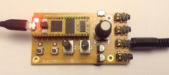
I’ve also picked up a “pod” which is a breakout board that includes the following:

  • 3.5mm stereo jacks for line level audio I/O, headphone output, and TRS MIDI input.
  • Built In headphone amplifier with dedicated volume control.
  • 2 Buttons, 2 RGB LEDs, and rotary encoder with push button.
  • SD Card Slot, and secondary USB micro port

There are a number of DIY experimenter style products that use the Daisy Seed. Here are a couple that might be worth a look (I’ve not used any of them):

Just doing an image search for Daisy Seed synth and quite a few come up!

Getting Started

There are several ways to start programming the Daisy Seed, one of which is using an online, web-based programing environment. I’ve stayed with familiar territory and installed support into the Arduino IDE.

This requires the following steps as described in the Arduino version of the Getting Started Guide:

  • Add in the Arduino board URL for the STM32 core and install “STM32 MCU Based Boards” from STMicroelectronics.
  • Install the STM32CubeProgrammer from ST (requires email registration).
  • Add the location of the STM32 tools to the PATH. For my Windows setup this means adding: %ProgramW6432%\STMicroelectronics\STM32Cube\STM32CubeProgrammer\bin to the system PATH.
  • Install the DaisyDuino library using the Arduino Library Manager.

Unfortunately one thing that wasn’t particularly clear as part of any of the above is that the STM32 core no longer supports the V1 strand of the Arduino IDE. I spent quite a chunk of the afternoon trying to work out why the build tools didn’t seem to be able to find all the things they needed. Eventually I stumbled across some replies in the STM32 core forums to some problems that stated that V1 was no longer supported.

For my initial experiments, I rolled back the version of the Arduino STM32 Core to version 2.7.1, which was the last release that supported V1.

At this point I was finally able to use the Arduino IDE to download the blink example using the configuration as per the getting started guide, but summarised as:

  • Board -> Generic STM32H7 Series
  • Board Part Number -> Daisy Seed
  • USB Support -> CDC (Generic Serial supersede U(S)ART)
  • Upload Method -> STM32CubeProgrammer (DFU)

To upload requires a RESET on the board with the BOOT button pressed.

Eventually I just updated my Arduino environment to V2 for other reasons 🙂

DaisyDuino Examples

There are a number of example scripts as part of the DaisyDuino library, and a number of them are provided that support the Daisy Seed Pod.

The Pod provides buttons, LEDs, pots, an encoder and MIDI and audio circuitry and there is a full suite of examples here, available under Examples -> DaisyDuino -> Pod.

The non-pod related Daisy Seed examples are listed here and can be found under Examples -> DaisyDuino -> Seed.

I downloaded the pod/SimpleOscillator example which does the following:

  • Encoder selects one of four waveforms.
  • Pot 1 selects the frequency.
  • Two buttons change the octave.

Full details can be found here: https://github.com/electro-smith/DaisyExamples/tree/master/pod/SimpleOscillator

Other examples for the Pod include:

  • ChordMachine – “A simple sine wave chord machine. Cycle through different chord types and inversions.”
  • Encoder – change the LED colour using the encoder.
  • EuclideanDrums – A kick and snare twin sequencer.
  • Looper – shows how to loop incoming audio.
  • Midi – MIDI controlled oscillator and filter.
  • MultiEffect – “Simple effects for incoming audio. Includes reverb, delay, and downsampling.”
  • MusicBox – “Generate random melodies.”
  • SimpleButton – “Example showing basic usage of pushbutton switches for momentary and latching behavior.”
  • SimpleLed – “Example showing basic usage of RGB LED by mapping R/G values of LED 1 to knob.”
  • SimpleOscillator – “Example showing a basic SimpleOscillator with controls.”
  • StepSequencer – “Simple 8 step sequencer. Has controls per step for envelope decay, pitch, and step activation.”
  • SynthVoice – “Simple Synth voice with resonant filter, self cycling envelope, and vibrato control.”

Example Hardware Connections

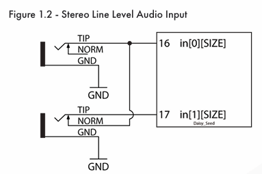
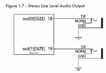
The datasheet contains a number of connection diagrams showing how potentiometers, buttons, LEDs, and audio jacks can be connected to the Daisy Seed.

Audio input and output for example are as follows:

This is essentially what the Daisy Pod provides – basic IO and connections following these patterns, along with a headphone amplifier and MIDI.

I might have missed it, but looking at the Pod schematic and the board itself, I believe there is an option to switch from MIDI TRS “A” to MIDI TRS “B” by swapping some 0R resistors on the rear of the Pod.

Key Hardware Parameters and Features

Here is a list of various odds and ends that are tucked away in the datasheets or wiki that I might want to note:

  • Most GPIO is 5V tolerant apart from D24, D25, D28, D29, D30 which are 3V3 only. The datasheet states 0 and 3V3 as the typical operating range for all GPIO.
  • VIN supports 5V to 17V.
  • Audio inputs/outputs: -1.8V to 1.8V.

According to the datasheet it is ok to power the Daisy Seed from VIN and USB at the same time.

Audio in and out was originally provided by an AK4556 (the last revision for which there is a full schematic published), then a WM8731 with the latest version using a PCM3060. This is connected to the STM32H7’s SAI1 peripheral.

Closing Thoughts

Whilst this has a whole range of IO and synth type examples, what I’m really interested in is the potential for processing audio via the audio input, so that is probably what I’ll be looking at the most.

For such a (relatively) cheap device, this certainly has a huge set of examples and applications. I can see why so many people have started building these into other products.

I can already imagine producing a Daisy Seed version of some of my own PCBs for example…

I should probably take a proper look at the non-Arduino environments too – I’ve been meaning to have a look at Pure Data for a while, so maybe this could be an excuse for that.

Kevin

#arduino #DaisySeed #oscillator #STM32

शून्यताwigalois@dresden.network
2024-11-12

"So how many #HP instruments do you need for happiness?" -- "Yes." (toc) #HP106B #Oscillator

Simple DIY Electronic Music Projectsdiyelectromusic.com@diyelectromusic.com
2024-08-15

A common early project for anyone starting to play around with analog synthesis is a “Baby8” step sequencer. There are many designs out there on the Internet and many ready-designed kits that can be bought and made. I can recommend the Rakit Baby8, which has some neat features. I’ve used it with my Educational Synth Thing.

  • Part 1 – This post with the introductory design information.
  • Part 2 – The design for a PCB based on the principles in the first post.
  • Part 3 – The build and test notes for the PCB.
  • Part 4 – Usage notes for the PCB and how to use it with the Educational Synth Thing.

This is a first look into how they work with a view to reinventing this wheel and eventually making my own.

https://makertube.net/w/eTG7VNtM31auPDdxuBFVkp

Warning! I strongly recommend using old or second hand equipment for your experiments.  I am not responsible for any damage to expensive instruments!

Here are some existing articles that detail the main concepts used in this project:

If you are new to Arduino, see the Getting Started pages.

Introduction

The basis of the Baby 8, at least all those that haven’t been reimplemented using a microcontroller, is the CD4017 decade counter chip. This has 10 outputs and each will be set HIGH in turn on reception of a trigger pulse, which makes this a very simple way of triggering different output steps, in sequence, one at a time, in response to some kind of pulsed or clock input.

There is also a octal counter, the CD4022, with 8 outputs but for some reason, everyone seems to use the 4017 even though most builds only use 8 steps.

I won’t go into the details of using the CD4017 as this Hackaday article provides a great introduction already, but I’ll summarise as follows:

  • Each of the outputs can be fed into a potentiometer which then allows each step to have a configurable voltage between 0 and VCC.
  • One of the outputs is also linked to the CD4017 RST pin which then resets the sequence. By having this configurable, different length sequences (up to 10) can be set.
  • Some circuits assume an external clock signal; some include an internal clock.
  • The internal clock signal often comes from a 555 timer or a simple inverter-based oscillator, each with a configurable frequency.
  • Output is the variable voltage from the potentiometers, which have to be summed together at the output.
  • A gate/trigger style output is required at the start of each sequence step, usually triggered off the same clock input.
  • Most designs include an LED for each step.

Some additional extras I’ve seen in some builds include:

  • A stop switch to pause the sequence.
  • Mute or skip switches to inhibit specific steps.
  • Single step or hold functions.
  • An LED for the clock.
  • A configurable pitch (voltage) offset for the outputs.
  • A configurable duty cycle for the gate (clock).

The key features I want are as follows:

  • 0-3V3 CV and either 3V3 or 5V gate, for use with my Educational Synth Thing.
  • Internal clock generation, no need for an external clock input.
  • LEDs per step.
  • Powered by 3V3 or 5V (to be decided).
  • Optional: 9V power supply.
  • Optional: buffered CV/gate jack outputs.

Ideally I’d like the 8 steps arranged in a circle, but that is to be decided too. I’m not sure if I’ll include the optional items, as there are already pretty well featured DIY kits available. I’ll probably just work on what I need for use with my educational synth thing.

I would like to include mute switches and some way to configure the number of steps in the sequence.

The other thing I’d really like to have done is to use “clear shaft” potentiometers, like those used on the Korg Volcas, but these seem pretty hard to find. Taiwan-based Alpha appear to do some, but they are quite costly and not easily available in the UK (without the minimum buys and high postage costs from a large professional distributor).

In the end, I decide to stick with normal pots and separate LEDs.

A note on clocks.

As already mentioned an internal clock source is often provided and these generally seem to be one of a couple of types from what I’ve seen.

The 555 timer is one option. The circuit will configure the 555 in astable, multivibrator mode which generates a square wave signal with the period (frequency) dependent on the components used. There are many tutorials online that talk about how to do this.

I’ll link to Mitch Electronics here as they provide a neat little kit for experimenting with them on their own, but I’ve also looked at these myself here: Simple Square Wave Oscillator PCB Design.

Other circuits use a schmitt trigger inverter oscillator circuit, or sometimes a NAND gate equivalent. There is a good discussion of how this works and some design considerations here:

The last article contrasts the use of inverters vs NAND gates and also discusses some of the issues relating to using TTL or CMOS logic for this purpose.

In terms of options for actual devices, I’ve picked out the following to consider:

  • CD40106 – CMOS hex Schmitt Trigger inverter. VCC=3-18V.
  • 74HC14 – CMOS hex Schmitt Trigger inverter. VCC=2-6V.
  • 74HCT14 – as above but supporting TTL loads. VCC=4.5-5.5V.
  • CD4093 – CMOS quad Schmitt Trigger NAND. VCC=3-18V.
  • 74HC00/74HC20 – single/dual Schmitt Trigger NAND. VCC=2-6V.

and so on.

The only major consideration for me is that if I can support it being powered from a 3V3 supply then that would mean that the default output will be in the neat 0-3V3 range I’d like for my educational synth. Essentially any of these would do that apart from the HCT variants of the devices.

This is the proposed circuit, using a NAND gate as an inverter. I’ll be using more NAND gates later too, so using a NAND here makes sense even if only used as an inverter.

As this will be powered from the 3V3 supply, I did some testing with different values for the capacitor and resistor and found the following frequency ranges:

010K100K500K2uF300Hz33Hz3Hz0.6Hz3.3uF240Hz24Hz2.5Hz0.4Hz4.7uF160Hz16Hz1.6Hz0.3Hz10uF70Hz7.5Hz0.7Hz0.2Hz

As this is the step controller for a sequencer, I went with a 4.7uF capacitor and 500K potentiometer, however I did find that with no resistance the square wave essentially becomes a triangle wave, so I’ve also added a fixed 10K resistor to give a resistor range from 10K-510K which ensures that the square wave is always fairly well defined.

In the end this gives me a frequency range of around 0.3Hz to 16Hz, or thereabouts. This is equivalent to between 20 and 960 steps a minute, give or take.

Cascading 4017 Counters

As the key idea with a looping 4017 counter is to use one of the outputs to reset the counter, it is actually possible to link several counters together and get them to reset each other. The key trick is to make use of the CLK inhibit (CI) pin. When this is high it stops the clock, so this can be used to ensure that a counter is only counting when it is it’s turn.

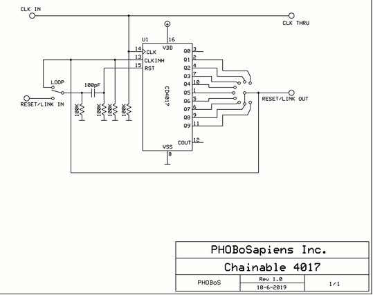
There is a detailed discussion of the ideas here: https://electro-music.com/forum/topic-63068.html In particular a number of the circuits posted by Phobos (one of which is also referenced by Kristian Blasol in his “Modular in a Week” video series here) work through the core idea.

The final suggested design is as follows:

The key principle here is that the CLKINH line has to be LOW for the counter to run. This is tied to the last output in the sequence, so when that goes HIGH one of two things could happen:

  • Without any chaining, i.e. for a single counter, this output is tied to the RST signal, so when it goes HIGH CLKINH also goes HIGH and stops the counter, but also RST temporarily goes HIGH too, which resets everything, including clearing the last output and thus resetting CLKINH back to LOW.
  • With chaining, i.e. with two counters linked as indicted above, then CLKINH goes HIGH which stops the counter and will remain HIGH until it gets RST. In this case that will only come from a chained 4017 further down the line.

Note: each of these signals is pulled LOW by default via a 100K resistor, and there is a 100pF capacitor in the RST line to ensure it only gets pulsed rather than staying HIGH.

What would be ideal for me is to have a way to break out the various signals required to cascade counters via a jumper header to allow units to be plugged into each other. Something to think about.

Parts list

  • 1x CD4093 Schmitt trigger quad NAND
  • 2x CD4017 decade counter
  • 16x LEDs
  • 16x 220Ω resistors
  • 1x 10KΩ resistor
  • 2x 100KΩ resistors
  • 1x 500KΩ potentiometer
  • 1x 4.7uF electrolytic capacitor
  • 2x 100pF ceramic capacitors
  • Breadboard and jumper wires

The Circuit

The core oscillator and counter circuit is shown above. This will run the counter at a frequency set by the potentiometer and cycle through the display of all 8 LEDs. The circuit can be powered by 3V3 or 5V.

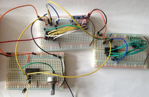
The following shows how the circuit can be expanded with a single cascade to a second 4017 counter.

The oscillator section is the same but the clock output is now connected to the clock input for both 4017s. As described earlier, the Q8 output of one 4017 is connected to both its own CI pin and the other counter’s RESET pin (via the 100pF capacitor).

To turn this into a Baby 8 sequencer requires the use of a potentiometer on the output of each of the 4017’s counters and some means of generating a GATE signal.

But at this stage, I’m going no further with the solderless breadboard implementation and switching over to a PCB, which I’ll describe in my next post.

Closing Thoughts

It has been really interesting to work through the use of a NAND oscillator and how it can drive cascading 4017 timers. The video at the start shows them in action, although I only had an 8-way and 6-way LED block to use, so I stopped the second one after 6 steps.

The next part will consider how to generate control voltages for pitch alongside a GATE signal to trigger an actual note.

Kevin

https://diyelectromusic.com/2024/08/15/baby8-cv-step-sequencer-part-1/

#baby8 #oscillator #sequencer

Simple DIY Electronic Music Projectsdiyelectromusic.com@diyelectromusic.com
2024-07-02

My Educational DIY Synth Thing is meant to be a platform for experimenting and one easy way to get started on that is with the addition of some off-the-shelf audio and synthesizer-oriented electronics kits.

Optional additional things to try:

This post will collect together any kits I’ve bought that seem to work pretty well with my Synth Thing. I’ll come back and update it as I add more things I’ve found that work.

Important Note: In most cased I’ve just stumbled across these kits and bought them myself directly. I’ve not been asked to mention them or been sponsored in any way by the people who have made them. They are all just neat kits I’ve found that seem to work ok with my Synth Thing. No endorsement or fit for any purpose is implied. Other kits, I’m sure, are available! In fact feel free to drop me a note of any you know about in the comments. 🙂

Warning! I strongly recommend using old or second hand equipment for your experiments.  I am not responsible for any damage to expensive instruments!

If you are new to electronics, see the Getting Started pages.

Mitch Electronics Synth Kits

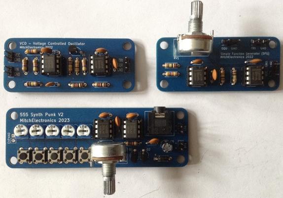
Mitch Electronics produce some pretty simple, inexpensive, soldering kits, several of which have audio or synthesizer related purposes. I picked up the following:

The build guides are very well done, schematics are published online and one feature I particularly liked is that each guide includes a link to an embedded version of what looks like Lush Projects Javascript based Circuit Simulator set up for the circuit for that kit. That is a really nice touch!

Each guide has a description of how the circuit works which again is really easy to follow. My only criticism is that it might have been useful to add the specs for each module to the guides too so that all the information you’d need for further integration can be found in one place. The specs are on the product page in the shop area at the time of writing, but not the guides themselves.

Notes about the kits:

  • As the oscillators are based on the LM358 they can probably be powered by quite a range of voltages. The spec suggests 5-16V.
  • The oscillators output a square wave at 0 to VCC-1.5V. The triangle is a lot less.
  • The oscillators have a frequency range of 0 to 36kHz (ish, depending on VCC and tolerances of components).

Voltage Controlled Oscillator

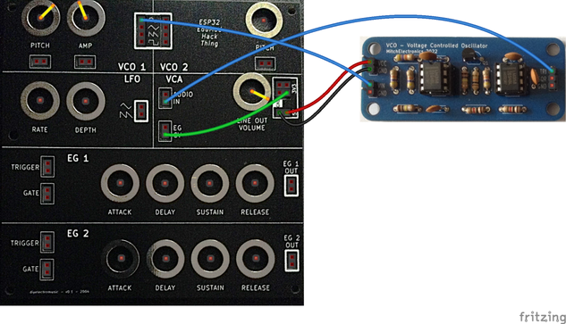
I’ve hooked this up to my Educational DIY Synth Thing as follows:

Note I’m using the 5V supply to power the board. This will give me a maximum voltage to feed back into the synth thing of ~3.5V.

In use I found that the triangle wave has a much lower amplitude, but also a DC offset, so the signal is around ~1.3V pp with a DC bias of around 1.8V or thereabouts. Note this is still fine to get fed back into the audio input of the VCA stage of the synth thing.

I’ve configured it so that the Synth Thing VCO1 is acting as the control voltage for the Mitch Electronics VCO. Having control over the frequency and amplitude gives all sorts of possibilities for frequency modulation, as can be seen in the following oscilloscope trace. This is a trace at the audio input to the VCA, hence the bias in the signal is evident. This is a trace of the Synth Thing VCO outputting a sine wave into the Mitch Electronics VCO outputting a triangle wave.

The VCO is excellent for use with my Synth Thing. The only downside is that the square wave output is so much louder than the triangle wave, but that can be compensated for if required.

Simple Function Generator

The Simple Function Generator (SFG) works fine, but its application “out of the box” with the Synth Thing is a little limited. Given how the Synth Thing isn’t very good at modulating its own oscillators at audio frequencies, the SFG could be used as an independent oscillator but not much else.

However, if C1 (100nF) is replaced with a 10uF non-polar capacitor then the frequencies generated are in the range 0.5Hz to around 1kHz which is much more use to me as an additional LFO. Note I believe it has to be a non-polar capacitor rather than an electrolytic as I think the voltage is oscillating across the capacitor. But I could be wrong.

Here is how to use it as an LFO for the VCO1 pitch CV input. Notice that C1 has been changed.

555 Synth Punk

The 555 Synth Punk is a fun thing. This is essentially an Atari Punk Console with one of the pots replaced by a series of button-activated tunable presets. This in theory allows for five “notes” to be tuned up. In practice this isn’t as easy as it sounds due to the nature of the APC and the stepping function.

One minor annoyance for me is that the buttons are ordered so that the lowest note corresponds to the button on the right hand side. I really wish it was the left as you’d expect with a keyboard. There is room for expansion to more buttons, but as far as I can see no option for integrated this into my Synth Thing other than taking the audio output itself. There is no access to the voltage control for example. But this is a neat kit none-the-less.

Summary

The Simple Function Generator and 555 Punk Synth are neat kits for stand-alone purposes and general messing around as they stand.

But the VCO and a tweaked SFG are perfect for adding to my Synth Thing as an extra oscillator and LFO.

Rakit Baby8

The Baby8 sequencer is a pretty common circuit around the Internet and there are a number of kits available in a variety of form factors.

I have a Rakit version, which can be found here: https://www.rakits.co.uk/product/baby8-sequencer/

This is a pretty nice kit and can be used to generate a 0-5V CV and 5V gate signal for driving an analog synth. I’ve hooked it up to my Synth Thing as follows.

The Rakit Baby8 has a 6-way header which can be used to tap off the power, CV and gate signals and is designed to match up with the Rakit APC kit (which I also have). The header has the following pinout:

  • 5V VCC
  • APC CV1
  • APC CV2
  • Gate
  • Normal CV
  • GND

In this case, I’m not using the APC compatible CVs (I believe they are scaled to drive the APC in a more useful manner) or the 5V VCC connection. I’ve just connected the two GNDs together and then hooked up the normal CV and gate signals to my Synth Thing as follows:

  • Baby8 CV -> VCO1 Pitch.
  • Baby8 Gate -> EG 1 Gate+Trigger.

Here is a short video of it in action. This is a great kit!

https://makertube.net/w/nB8uXAXsM3r5LXp5WT2Hqg

MiniMo

One of the existing synths that started me off down this page was the MiniMo synth, based on an ATtiny85 so naturally it is worth looking at how this can be used with the Synth Thing too.

This shows how to connect it up as an additional oscillator (in DCO mode).

Key points:

  • The MiniMo could be powered from its own batter, 5V or 3V3. I’ve used 5V which comes directly off the regulator in the Synth Thing rather than via the ESP32 module (which is the case for the 3V3 link).
    • The above shows how to connect GND and 5V to the MinoMo.
    • Note that the power jumper on the MiniMo (shown in orange) must be set to “Ext”.
    • In principle this means the MiniMo output could reach 5V too, but that is not an issue for the VCA’s audio input.
  • Either of the outputs (jumper 1 or 2) from the MiniMo can be sent to the Audio In of the VCA. Only the “+” link is required as the GNDs are already tied together via the power link.
  • The output from the Synth Thing oscillators (VCO or LFO) can be used to drive either the pitch (input 3) or amplitude (input 4) of the MiniMo. Again only the “+” link is required.

In the above, I’ve linked the LFO of the Synth Thing to the amplitude of the MiniMo; the VCO of the Synth Thing to the pitch; and used a constant input to the VCA (from 3V3 volts).

Some internal adjustments of levels on the MiniMo may be required as the Synth Thing is sending in 3V3 level control voltages, but in practice it seemed to work fine for me.

MiniMo as a Signal Processor

Several of the MiniMo programs perform signal processing:

In each of these cases, Input 3 is the modulation control and Input 4 is the audio signal in. These can be used by connecting Input 3 (modulator) to the Synth Thing for a control voltage – e.g. from the LFO; and connecting Input 4 (audio) to one of the Synth Thing’s audio signals – e.g. the output from the VCOs.

These will require the re-programming of the MiniMo. There are details of how to do that on the original MiniMo site here; and some details of how to get this working with a more recent Arduino environment here.

Closing Thoughts

I’m really pleased at how usable these integrations with other kits are. The Mitchelectronics VCO/LFO is a really useful addition. The Rakit Baby8 works great. The MiniMo has lots of possibilities for additional signal processing.

If you know of an interesting kit that might work well with the Synth Thing, be sure to let me know in the comments!

Kevin

https://diyelectromusic.com/2024/07/02/educational-diy-synth-thing-part-6/

#apc #baby8 #esp32 #mitchElectronics #oscillator #rakit #synthThing #vco

2024-05-26

In the first part I described the concept and basic design parameters I was looking for and then in Part 2 I looked at the detailed electronic design for a board based on the ESP32 WROOM module I have. In this part I go into detail about the code.

  • Part 1 – This introduction and high-level design principles.
  • Part 2 – Detailed design of an ESP32 based PCB.
  • Part 3 – Software design.
  • Part 4 – Mechanical assembly and final use – todo.

Warning! I strongly recommend using old or second hand equipment for your experiments.  I am not responsible for any damage to expensive instruments!

The ESP32 EduMod Hacked Synth Thing

As mentioned in the last part, the principles and code I’m using are taken from these previous posts:

I also now have a built PCB design to make development and testing a lot easier.

Recall the following design choices:

  • The two ESP32 DACs are the output for two envelope generators, each driven by four pots (in standard ADSR configuration), a trigger and a gate signal.
  • There are ESP32 PWM outputs for two VCOs, each with four waveforms (sine, triangle, saw, square) and an analog input (pot or CV) for frequency and amplitude.
  • ESP32 PWM outputs are also used for a LFO with rate and depth analog controls.
  • The ESP32 UART is used for MIDI in.
  • ESP32 digital IO is used for the envelope GATE and TRIGGER signals, although they are level inverted, i.e. they should be read as active LOW.

Othe points to note:

  • There are three “native” analog inputs used for the two VCO pitch and amplitude CVs. All other pots are read via a CD4067 16-way multiplexer.
  • Software will determine how the VCO CVs interact with the potentiometers.
  • The UART RX pin will be used for MIDI and the UART TX pin will be used for one of the PWM outputs, so there will be no serial port (via USB) for diagnostic output.
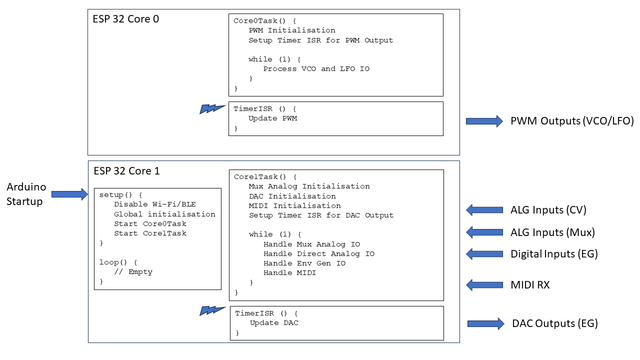
  • The ESP32 is a dual core microprocessor, so the aim is to split the functionality across the two cores.

High Level Design

The tasks will be split as follows:

  • Core 0:
    • Runs the PWM timer at 32,768Hz (although the sample rate will be half this – more on that later).
    • Manages the PWM outputs for the two VCOs and the LFO.
  • Core 1:
    • Runs the EG timer for the DAC at 10,000 Hz.
    • Handles the reading of all the IO: “real” analog values; multiplexed analog values; digital IO.
    • Handles MIDI.

Multicore ESP32 Arduino

Multicore support for the ESP32 on Arduino is provided using FreeRTOS tasks. For a FreeRTOS application, the default Arduino setup()/loop() will run on core 1. However, once tasks have been created to run on the second core, the default loop is no longer used (I believe).

FreeRTOS enables multitasking on a single CPU (core), each with its own internal priority relative to other tasks. But I’m only using it to start a single task on each core. This is achieved using the xTaskCreatePinnedToCore() function. The last parameter specifies which core to use and the 5th parameter indicates the priority – both are set to “1” as there is only a single task on each core.

The Arduino startup code has thus been reduced to the following:

void core0Entry (void *pvParameters);
TaskHandle_t core0Task;
void core1Entry (void *pvParameters);
TaskHandle_t core1Task;

void setup () {
xTaskCreatePinnedToCore(core0Entry, "Core 0 Task", 4096, NULL, 1, &core0Task, 0);
xTaskCreatePinnedToCore(core1Entry, "Core 1 Task", 2048, NULL, 1, &core1Task, 1);
}

void loop () {
// No main loop here
}

void core0Entry (void *pvParameters) {
Task0Setup();

for (;;) {
Task0Loop();
vTaskDelay(1); // Allow FreeRTOS IDLE to maintain watchdog
}
}

void core1Entry (void *pvParameters) {
Task1Setup();

for (;;) {
Task1Loop();
vTaskDelay(1); // Allow FreeRTOS IDLE to maintain watchdog
}
}

I’ve simulated the setup()/loop() pattern in each of the task entry points. One thing I quickly found was that if the tasks run with no release of the processor, then FreeRTOS will fail with a watchdog error.

This is why each task includes a vTaskDelay(1) call to allow FreeRTOS to do whatever it needs to do as part of its “idle” processing.

The other thing to be careful of, which would be the same even in a single core application, is that the timers and their timer interrupt routines also allow some general processing time on each core. This will become important further in the discussion.

Task 0: PWM Generation

The essence of Task 0 is the code from ESP32 and PWM. In order to simplify things I’ve created a basic oscillator class as follows:

class COsc {
public:
COsc ();
~COsc (void);

void Setup (int pwmpin, int wave, bool lfo=false);
void QuadSetup (int sinpin, int sawpin, int tripin, int squpin);
void ScanPWM (void);
void SetFreq (uint16_t freq, uint16_t vol=MAX_VOL);
void SetMVolts (uint32_t mvolts, uint16_t vol=MAX_VOL);
}

Initially the plan was to have one instance per PWM output. The pin and required waveform is configured as part of the call to the Setup() function.

But then I decided it would be more efficient to utilise the fact that the same index and accumulator can be used to read through each of the four wavetables, so created the idea of a “quad” oscillator. This just requires the four PWM pins to be used to be specified as part of the call to QuadSetup() and eliminates several calls into the ScanPWM function for separate oscillators.

There are two ways to set the oscillator’s frequency output. One is to pass in the frequency directly, the other is to pass in a millivolt reading from a potentiometer based on a 1V/oct scaling. The “zero volts” frequency is preset to be 65.406Hz, i.e. C2.

The frequency is derived from the millivolt reading using the following:

void COsc::SetMVolts (uint32_t mvolts, uint16_t vol) {
// Set frequency according to Volt/Oct scaling
// Freq = baseFreq * 2 ^ (voltage)
//
float freq = FREQ_0V * (powf (2.0, ((float)mvolts)/1000.0));
int f = (int)freq;
SetFreq(f, vol);
}

With the default settings this class can be used for both VCO and LFO, but the lowest frequency for the LFO was just 1Hz. Consequently, I’ve added the option to specify a “LFO” setting as part of the single oscillator Setup() function. If enabled, then the oscillator runs 10x slower than default. This allows for frequencies down to 0.1Hz, but does mean that the frequency or millivolt parameters are now treated as being 10 times smaller than their values would imply.

Note when MIDI is added into the mix, I just use the NoteOn message to change the base frequency used for the oscillators.

The ScanPWM() function is designed to be called from the interrupt routine running at the sample rate.

The oscillators are thus created as two Quad oscillators (one per VCO) and two single oscillators for the dual waveforms of the LFO:

#define OSC_VCO1 0
#define OSC_VCO2 1
#define OSC_LFO1 2
#define OSC_LFO2 3
#define NUM_OSC 4
COsc *pOsc[NUM_OSC];
int pwmpins[NUM_OSC][4] = {
{17,18,5,19},
{21,22,1,23},
{16,0,0,0},
{13,0,0,0}
};
int oscwaves[NUM_OSC] = {
OSC_WAVES, // VCO 1 (quad)
OSC_WAVES, // VCO 2 (quad)
OSC_TRI, // LFO
OSC_SAW
};

void oscSetup() {
for (int i=0; i<NUM_OSC; i++) {
pOsc[i] = new COsc();
if (oscwaves[i] == OSC_WAVES) {
// This is a quad oscillator
pOsc[i]->QuadSetup (pwmpins[i][0], pwmpins[i][1], pwmpins[i][2], pwmpins[i][3]);
} else {
// A single oscillator - these are the LFOs
pOsc[i]->Setup (pwmpins[i][0], oscwaves[i], true);
}
}
}

The timer configuration for Task 0 is as follows:

#define TIMER_FREQ  10000000  // 1MHz * 10 (0.1uS)
#define TIMER_RATE 305 // 30.5 uS * 10

Task0Timer = timerBegin(TIMER_FREQ);
timerAttachInterrupt(Task0Timer, &Task0TimerIsr);
timerAlarm(Task0Timer, TIMER_RATE, true, 0);

This generates a timer interrupt running at 32,768Hz from a 10MHz timer

However, servicing 10 PWM outputs means that there is no time remaining once interrupt processing is complete for any other operations. Consequently, I set things up so that the PWM outputs are updated in two blocks of 5, meaning that the effective sample rate for PWM purposes is actually now 16,384Hz:

int toggle0;
void ARDUINO_ISR_ATTR Task0TimerIsr (void) {
toggle0 = !toggle0;
if (toggle0) {
pOsc[OSC_VCO1]->ScanPWM();
pOsc[OSC_LFO1]->ScanPWM();
} else {
pOsc[OSC_VCO2]->ScanPWM();
pOsc[OSC_LFO2]->ScanPWM();
}
}

The main Task 0 Loop just pulls in the analog IO values that have been read as part of the processing of Task 1. These values are then used to set the frequencies of each VCO and the LFO.

Task 0: VCO Control

The VCO potentiometers and CV inputs have to be combined to determine the frequency and amplitude of the PWM signal.

In terms of amplitude, I’ve chosen to use the maximum of the pot or CV input to set the amplitude of VCO 1. Note that VCO 2 has no amplitude input, although with hindsight, I could have included a pot even though I’ve run out of GPIO pins for a CV input.

This means that the pot has to be turned fully “off” for the CV to become significant.

In terms of setting the frequencies, I initially thought about some kind of frequency modulation, which would have been good for linking the two VCOs together, but then decided actually I wanted a more straight forward relationship between pot and CV to allow the use of the LFO or the EGs for pitch. The result is going for a simple summation of the two inputs which gives a 3 octave range (started at C2) for each of the CV and pot, but when combined could give up to a 6 octave spread of frequencies.

When MIDI is enabled, that will set the base frequency for the summation rather than defaulting to C2. This will set the base for both VCOs, so the pots/CVs could be used for a detuning style effect.

Note: Due to the issues with the choice of pins for the inputs, the base level of the CV input for VCO2 is floating at around 300-600mV. The default (unconnected) configuration introduces an element of detuning. If the CV inputs are not wanted, then it is recommended to connect them to GND to eliminate this effect.

The result of taking this approach, combined with the frequency of scanning the inputs, means that if one VCO is used to set the frequency for the other, then it probably won’t track the voltages accurately enough for a smooth modulation. But it does generation quite a wacky “sample and hold” style aliasing effect, which actually I quite like.

I could try to do something about that, but I think in reality this is a use-case where a purely analog VCO can be added via breadboard as part of the experimentation which can be driven from the PWM VCOs – that should enable a number of possibilities for more complex oscillator modulation.

There is also some clipping at higher LFO frequencies if used as the amplitude input. This needs to be investigated to see if that is a bug in the code or handling of the CV somehow.

It is possible that this, and the aliasing of pitch, is a consequence of the frequency of scanning the analog inputs or the speed of the analogRead() function itself – it’s pretty slow. Some investigation is required to experiment with changing the frequency of the reading or rewriting to use the ESP32 API rather than the (slower) Arduino analogRead() function (more on that later).

Task 1: IO Scanning

All the IO is scanned as part of Task 1’s main processing loop. This has to cover the following:

  • Real analog values from the inputs corresponding to the VCO CVs.
  • Multiplexed analog values for all the pots for the VCOs, LFO and two EGs.
  • Digital IO for the EG gates and triggers.

I started off reading the “real” analog IO associated with the VCOs in task 0, but found that it just wasn’t being scanned frequently enough to function in any useful manner. Also, the calls to analogRead() incur some kind of processing overhead that appears to interfere with the timing of the PWM timer interrupt, leaving “blips” in the output.

I started to think about writing a FastAnalogRead() function to use the ESP32 SDK directly rather than the Arduino analogRead() function, but before doing that moved all the IO processing over to Task 1. It turns out that this seems to work adequately so if I’ve not done that at present.

But one consequence of this chain of thought is that I now have two sets of functions performing my own analog IO reading:

  • MuxAnalogRead()
  • FastAnalogRead()

Which both perform in very similar ways. I’ll describe the API for MuxAnalogRead(), but the same principles were used for FastAnalogRead() too.

void MuxSetup(void);
void MuxLoop(bool bVoltageReading=false);
void MuxLoopSingle (uint8_t pot, bool bVoltageReading=false);
uint16_t MuxAnalogRead (uint8_t pot);
uint32_t MuxAnalogReadMilliVolts (uint8_t pot);

The two Loop functions are designed to perform the actual reading from the hardware. Loop will read all known values in a single scan. LoopSingle() will read a single pot.

The functions MuxAnalogRead() and MuxAnalogReadMilliVolts() are used to retrieve the previously read values.

Scanning is performed using either the standard analogRead() or the ESP32 API function analogReadMilliVolts(). This is why a bVoltageReading parameter is required as part of the two Loop functions. It would be possible to calculate one from the other for every reading, but I’ve opted not to do that in order to keep the calculations required as part of a read as minimal as possible.

This allows the scanning of the hardware to happen on one core (in Task 1 in this case) yet be read from the other (Task 0).

Digital IO processing just requires monitoring the trigger and gate inputs for a HIGH->LOW transition and call the appropriate triggerADSR() or gateADSR() functions as required, although there is a bit more logic required to work in the MIDI input.

The actually scanning of IO is split over the different scans of the Task Loop as follows:

#define S_MUX (NUM_MUX_POTS-1)
#define S_FASTIO (S_MUX+1)
#define S_DIGIO (S_FASTIO+1)
#define S_ALGIO (S_DIGIO+1)
#define S_MIDI (S_ALGIO+1)
#define S_LAST (S_MIDI+1)
int taskState;

void Task1Loop(void)
{
if (taskState <= S_MUX) {
// Read each MUX pot in turn
switch (taskState) {
case 5: // VCO 1 CV
case 7: // VCO 2 CV
// These are read in millivolts...
MuxLoopSingle(taskState, true);
break;
default:
// These are read as 12-bit raw 0..4095
MuxLoopSingle(taskState, false);
break;
}
}
else if (taskState == S_FASTIO) {
Task1FastAlgIOLoop();
}
else if (taskState == S_DIGIO) {
Task1DigIOLoop();
}
else if (taskState == S_ALGIO) {
Task1AlgIOLoop();
}
else if (taskState == S_MIDI) {
Task1MIDILoop();
}
else {
taskState = S_LAST;
}
taskState++;
if (taskState >= S_LAST) {
taskState = 0;
}
}

Task 1: Envelope Generation

The core of the envelope generation code is from ESP32 DAC Envelope Generator, but once again the code has been refactored into a class as follows:

class CEnv {
public:
CEnv ();
~CEnv (void);

void setADSR (int eg_a, int eg_d, int eg_s, int eg_r);
uint8_t nextADSR (void);
void triggerADSR (void);
void gateADSR (bool gateOn);
void dumpADSR (void);
}

One change is setting the ADSR parameters in a single call. The values are assumed to be potentiometer readings in the range 0..4095.

Two envelope generators are created by Task 1:

CEnv *pEnv[NUM_ENV];

void envSetup() {
for (int i=0; i<NUM_ENV; i++) {
pEnv[i] = new CEnv();
}
}

The nextADSR() function has to be called for each envelope generator from the timer interrupt routine.

The timer configuration for Task 1 is as follows:

#define TIMER_FREQ  100000  // 100kHz (0.01mS)
#define TIMER_RATE 10 // 0.1mS

Task1Timer = timerBegin(TIMER_FREQ);
timerAttachInterrupt(Task1Timer, &Task1TimerIsr);
timerAlarm(Task1Timer, TIMER_RATE, true, 0);

This generates a 10kHz sample rate for the EGs from a 100kHz timer signal.

Task 1: MIDI

I’m using the standard Arduino MIDI library. There are a couple of points to note however:

  • MIDI will set the TRIGGER and GATE according to the reception of NoteOn and NoteOff messages.
  • I will need to keep track of which note is playing so that overlapping NoteOn/NoteOff messages don’t confuse the GATE handling.
  • As I’m reusing the TX pin as a PWM output, PWM initialisation must happen after MIDI initialisation, otherwise MIDI will assume the use of both RX and TX.
  • Serial MIDI by default implements “software MIDI THRU” so this needs to be disabled using setThruOff().
  • MIDI will set the base frequency used for the VCO controls, so the pot and CV will add to the MIDI frequency.

It isn’t clear what should happen with regards to frequency on NoteOff. Here are some options:

  • Reset back to default base frequency on NoteOff (the “0V” state), but this has the disadvantage that the frequency changes as soon as the gate signal initiates the Release state of the ADSR.
  • Wait until the envelope has finished the Release stage to reset the base frequency. This seems sensible when using the EGs, but has the disadvantage that when just using MIDI to set pitch, it will not revert back immediately on “key up” – it will only revert back when the envelope is complete, which is confusing if the EG is not being used.
  • Don’t reset the base frequency, this means the note will continue on the last used frequency until a new note is played.

I’ve opted not to reset the base frequency on the basis of: if MIDI on/off handling is required, then it will probably be using envelopes anyway. If not, then having only MIDI on setting a sustained frequency sort of makes more sense to me.

Closing Thoughts

The code will continue to evolve as I keep tinkering with it, but the current state can be found in the GitHub repository for the project here: https://github.com/diyelectromusic/ESP32EduModHackThing

There are still a few quirks and things I might continue to investigate and possibly optimise. Specifically:

  • The performance for reading the “real” analog CVs for the VCOs.
  • The frequency handling with respect to MIDI.

But in general I think it is starting to get pretty usable.

Kevin

https://diyelectromusic.wordpress.com/2024/05/26/educational-diy-synth-thing-part-3/

#adsr #define #envelopeGenerator #esp32 #lfo #oscillator #vca #vco
2024-05-09

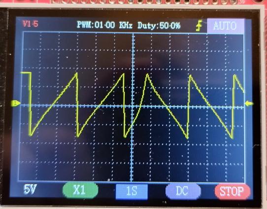
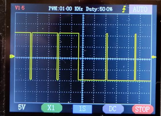
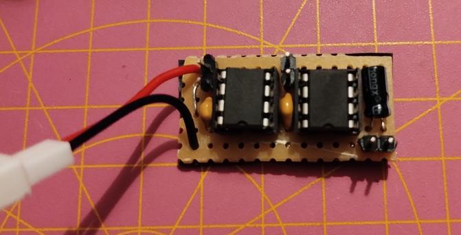
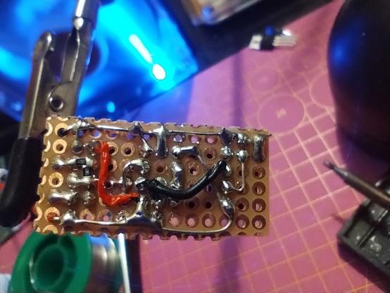
At least the single rail #opamp #oscillator circuit works with these counterfeit chips. Maybe I'll turn them all into #LED blinkies and Schmitt triggers.

#electronics

Podolski

Created in 2005 and still going strong. Podolski is a free, straightforward, CPU-efficient virtual analogue synthesizer. One oscillator, one filter, one envelope and an arpeggiator/sequencer. Simple, but with a few tricks up its sleeve. Create high quality sounds with ease.

u-he.com/products/podolski/

#linux #podolski #synthesizer #oscillator #sequencer

2024-03-20

I mean, an advantage of not doing anything to the is that I get to use it for family movie night, but also I can expect it to not burn my off.

It was really tempting today to remove the color wheel. I found out that others have used a thing called a to the back signal from the colorwheel motor. So you can remove the motor altogether and go to a projector. I'm exposing another photo before bed right now. Halfway there

GVST GSinth2 is a free VST synthesizer plug-in.

It has 3 oscillators with independent settings that can be used to create interesting sounds. Randomize buttons allow for quick experimentation with sounds.

gvst.co.uk/gsinth2.htm

#linux #GSinth2 #vst #synthesizer #oscillator #oscillators

2024-02-10

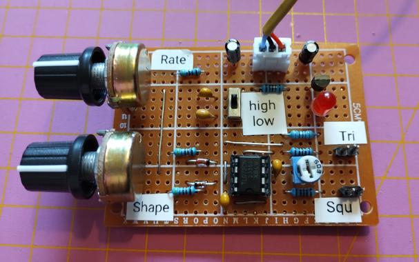
The last module of my #diysynth that I had on breadboard is now soldered to a #perfboard. It's a #LFO with triangle and square wave output, with shape #potentiometer that changes the triangle wave towards sawtooth or ramp, and the duty cycle of the square wave between 5% and 95%.
It has two speed settings with 0.12 to 5.3 Hz, or 1/80th to 0.5 Hz frequency. I might build a second one with different capacitors for higher frequencies.
#soldering #synthesizer #oscillator #electronics

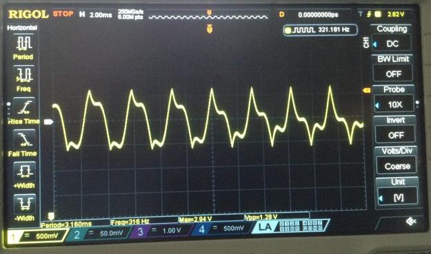
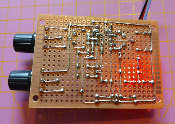
the finished LFO module. it has two potentiometers for rate and shape, a switch for high or low setting, and two outputs, for triangle and square. in the middle is the TL072 OpAmp and a trimmer for adjustments. the LED is driven by the triangle waveback side of the board showing the soldering. the LED is shining throughoscilloscope showing the output of the triangle wave with shape pot turned to both extremes. on the left a ramp wave, on the right a sawtooth wave. the edges are almost perfectoscilloscope showing the square wave with the shape pot turned to both extremes. it goes from 95% duty cycle on the lefy to 5% on the right
𝟜𝟚𝟘 𝑠𝑖𝑛𝑐𝑒 𝟿𝟻420@mrbot.de
2024-01-17

Aaaaaaaaah madness! The 1000 Oscillator Megadrone!!!

https://youtube.com/watch?v=c3wk9WWTfNs

#oscillator #madness #synth #tech #engineering

2023-12-22

It's almost done now. The main #circuit is soldered and tested, the boost converter is set to 9.2V and only the headphone jack and the cables to the main board are missing.
Some of the components are held in place by hot glue.
#AtariPunkConsole #synth #diysynth #soldering #555timer #555 #oscillator #hotglue

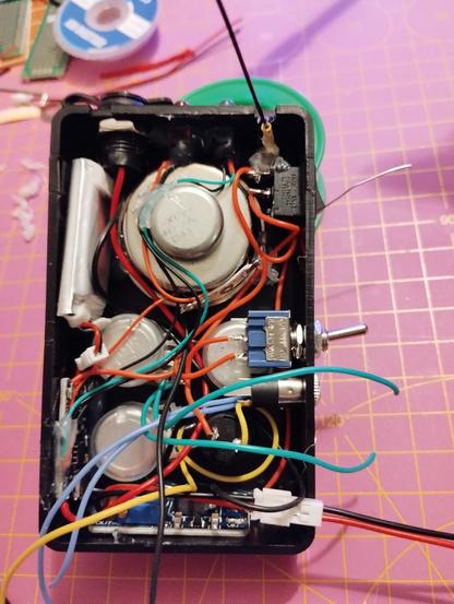
the finished circuit board for the Atari Punk Console. the two 555 timers, the capacitors and the connectors for the potentiometers can be seenback side of the circuit board. there are two jumper cables crossing other wires. it looks a bit messy, thoughthe open case filled with all components, except the main circuit board. almost all connections are done and a bit of hot glue keeps them in place

“Boris Johnson says he was not indecisive at start of Covid pandemic.”

Well, he *would* say that, but he’s not very sure…

theguardian.com/politics/2023/

#CovidInquiry #BorisJohnson #Oscillator

Client Info

Server: https://mastodon.social
Version: 2025.04
Repository: https://github.com/cyevgeniy/lmst