
#otd #startrek #aprivatelittlewar #kirk #spock #mccoy #bones #uhura #sulu #chekov #scotty #chapel #Nona #Tyree #Krell #DrMBenga #Apella #mugato #Yutan #startrek59 @trekcore
#Krell


Hoffentlich kommt der auch noch, wenn ich zurück in Deutschland bin
#Kino #JetztWohin #Habeck #Grüne
mit dabei:
Luisa #Neubauer, Tobias #Krell, Markus #Lanz, Jan „#Monchi“ Gorkow, Charly #Hübner, Maja #Göpel, Daniel #Günther, Samira #ElOuassil, Friedemann #Karig, Christian #Stöcker, Arun #Chaudhary
JETZT.WOHIN. | Homepage zum Film – Ab 7. Dezember 2025 im Kino
https://www.pandorafilm.de/filme/jetzt-wohin.html

#Methodologie #qualitativer #Sozialforschung
nach #Blumer (1969) drei #Voraussetzungen:
-> #Berücksichtigung #gesamter #wissenschaftlicher #Suche, nicht nur #Teilaspekt -> #Epistemologie
-> #Forschungsmethode ist der #Welt untergeordnet -> #Reflexion von #Widerspenstigkeit
-> Die #Antwort auf die #Forschungsfrage liefert die #empirische #Welt
#Lamnek, #Krell - #Qualitative #Sozialforschung, S. 89f.


#Vielschichtige #methodische #Vorgehensweise / #Untersuchungsform (#Approach), der #theoretische #Vorgaben der #Methodologie in #praktische #Handlungsanweisungen umsetzt, ohne #Erhebungstechnik zu sein. Das #Untersuchungsobjekt wird nicht #reduziert.
#Ziel: #theoretischen #Typus in seiner #inneren #Logik #erklären.
#Lamnek, #Krell - #Qualitative #Sozialforschung, S. 285f.
#Fallbericht #Fallanalyse #Fallmethode #Falldarstellung #Fallgeschichte #Fallbeschreibung


Forbidden Planet “Krell” Display – MIDI CC Controller – Part 2
This revisits my Forbidden Planet “Krell” Display – MIDI CC Controller using my Forbidden Planet “Krell” Display PCB with a Waveshare RP2040 to create more of a “all in one” device.
Warning! I strongly recommend using old or second hand equipment for your experiments. I am not responsible for any damage to expensive instruments!
If you are new to Arduino, see the Getting Started pages.
Parts list
- Updated Forbidden Planet “Krell” Display (see below).
- Completed Forbidden Planet “Krell” Display PCB Build
- Waveshare Zero format device (I’m using an RP2040)
- 4x 6mm brass spacers
- 4x 20mm nylon spacers
PCB
This requires a built of the Forbidden Planet “Krell” Display PCB with the following:
- 2 potentiometers
- MIDI IN and OUT
I’ve used potentiometers that are their own knob, as they only poke through the casing by around 5mm or so.
If it you are able to get longer shaft pots, then that would probably be worthwhile.
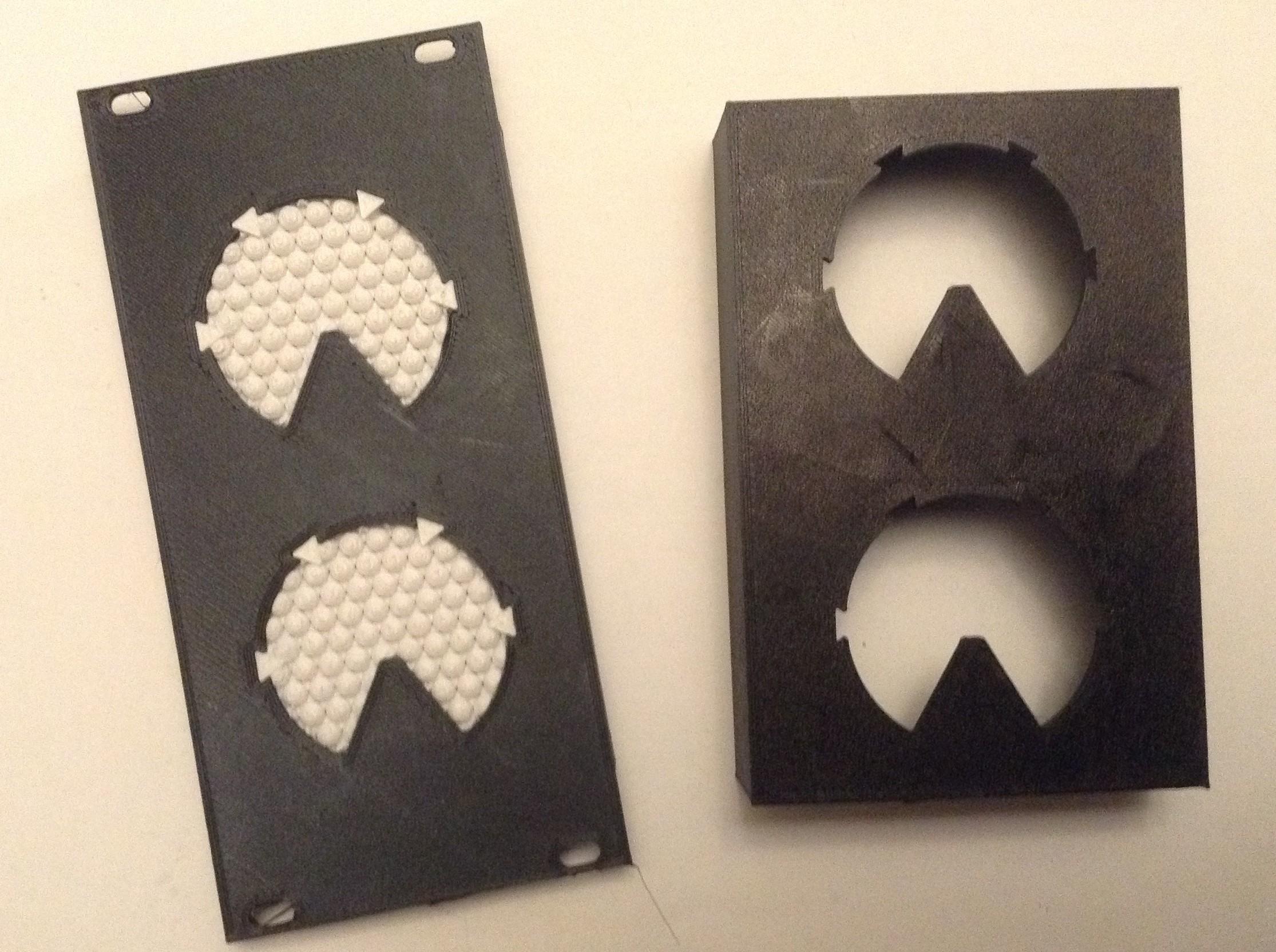
Updated 3D Printed Case
This requires the following from the Krell Display 3D Printed Case:
- 1x Frame
- 2x Inserts (with potentiometer holes)
- 1x EuroRack support
This requires the following options in the OpenSCAD code:
show_frame = 1;
show_quadframe = 0;
show_insert = 1;
show_support = 0;
show_quadsupport = 0;
show_eurorack = 0;
show_eurorack_support = 1;

alg_pot1 = 1;
alg_pot2 = 1;
alg_cv   = 0;
The frame does not really take into account the PCB at present, but I’ve reached the “good enough I want to do something else” stage, so I’ve just added a couple of small cut-outs (using a hacksaw) for the two MIDI sockets, and am content that the components stick out a bit from the back.
This cutout has to be 10.5mm from the end, 6mm wide, and 5mm deep.
At some point I might go back and design a deeper frame that has the cut-outs included and some kind of snap-on back to make it a self-contained box.
But for now, this is left as an exercise for, well, anyone else 🙂
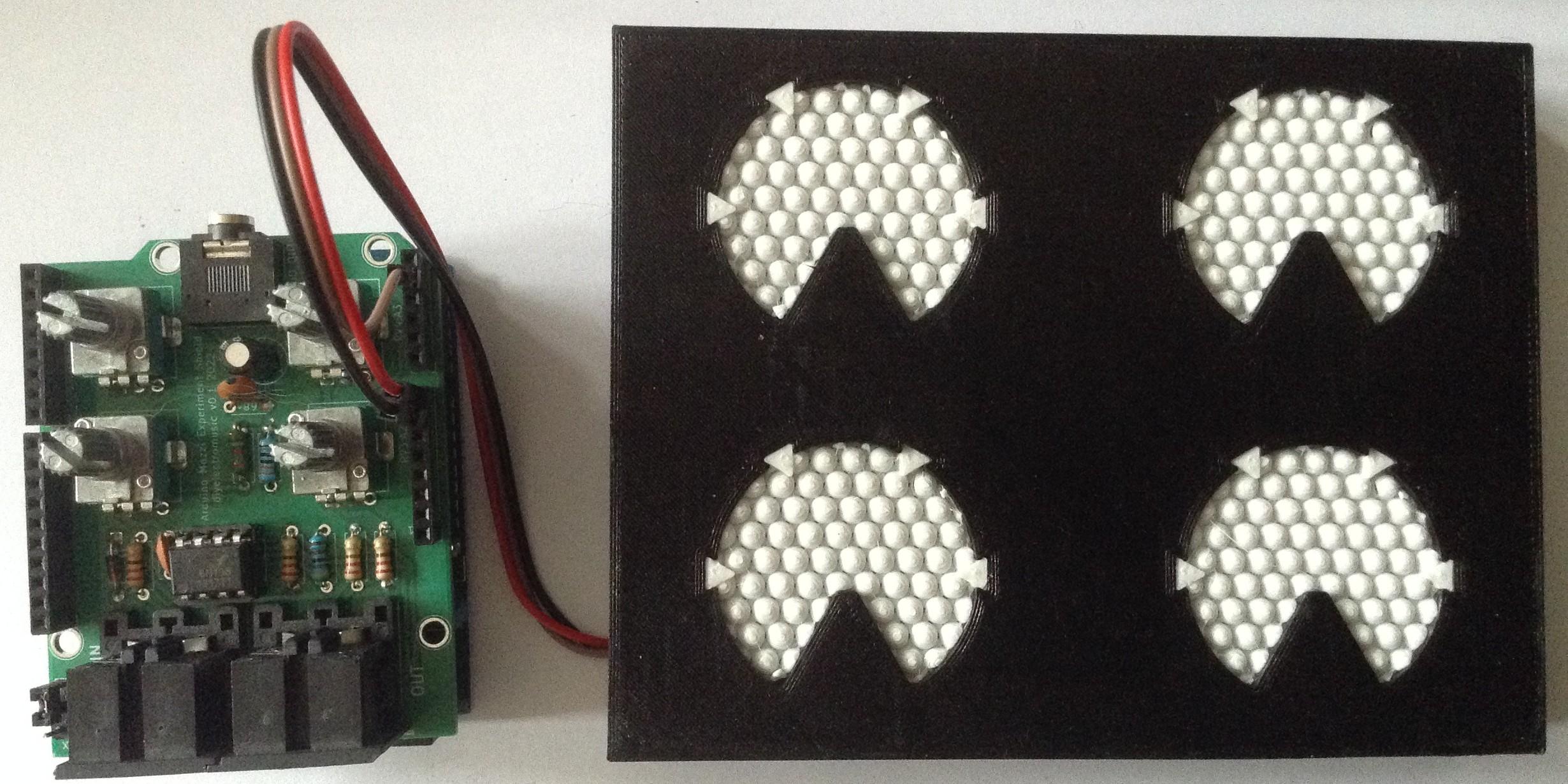
Construction
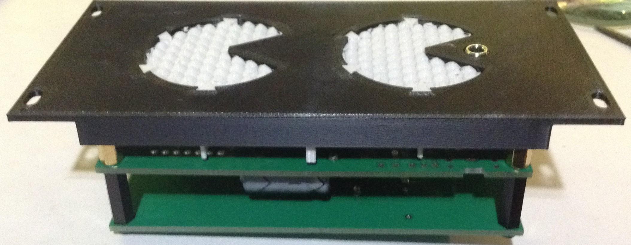
I’ve used four brass 6mm spacers to screw into the mounting holes in the frame. Then the PCB can be inserted, taking care to squeeze in the 3D printed support around the LEDs and pots, and fixed with 20mm spacers which will also act as “legs”.
The Code
I’ve used a Waveshare Zero RP2040 and Circuitpython for this build. This is a combination of some of the test code used for the Forbidden Planet “Krell” Display PCB but with added MIDI.
The code supports both Serial and USB MIDI.
I wanted an equivalent of the Arduino map() and constrain() functions and didn’t immediate spot them in Circuitpython so wrote my own:
def algmap(val, minin, maxin, minout, maxout):
    if (val < minin):
        val = minin
    if (val > maxin):
        val = maxin
    return minout + (((val - minin) * (maxout - minout)) / (maxin - minin))
This allows me to map the analog read values (0 to 65535) down to MIDI CC values (0 to 127) whilst also allowing for some inaccuracies (I’ve treated anything below 256 as zero for example):
alg1cc = int(algmap(alg1_in.value,256,65530,0,127))
I’ve used the Adafruit MIDI library, which I’m still not really a fan of, but I wanted to include MIDI THRU functionality to allow the controller to sit inline with an existing MIDI stream. But it doesn’t seem to work very well.
I was already only updating the LEDs/MIDI CC if the pot values had changed, to cut down on the number of Neopixel writes required.
I experimented with changing the scheduling of the analog reads and MIDI but that didn’t seem to help very much. In the end I made sure that all MIDI messages queued up in the system would be read at the same time before going back to checking the pots.
    msg = midiuart.receive()
    while (msg is not None):
        if (not isinstance(msg, MIDIUnknownEvent)):
            midiuart.send(msg)
        msg = midiuart.receive()
It will do for now. Moving forward, I might try the Winterbloom SmolMIDI library. If that still doesn’t give me some useful performance then I might have to switch over to Arduino C.
Closing Thoughts
The MIDI throughput is disappointing, but then I’ve never really gotten on with the Adafruit MIDI library. I use it as USB MIDI on Circuitpython is so easy, so will need to do something about that.
I’m still deciding on the PCB-sized supports too. The original seemed to have nicer diffusion of the LEDs, but that could have been the difference between 5mm SMT neopixels and these THT APA106s which seem more directional in the first place.
And I really ought to finish the 3D printed case properly too.
So this is “that will do” for now, but I ought to come back and finish it off properly at some point.
Kevin
#APA106 #circuitpython #ForbiddenPlanet #Krell #midi #midiController #NeoPixel #potentiometer #rp2040 #WaveshareZero


And a short demo of it in action.
Here is a 12 HP EuroRack version of my Krell Display with a single CV input.
https://diyelectromusic.com/2025/04/03/forbidden-planet-krell-display-eurorack-module/
Forbidden Planet “Krell” Display EuroRack Module
This project uses my Forbidden Planet “Krell” Display and the Forbidden Planet “Krell” Display PCB Design but with some slight variations that means it could be EuroRack mounted with a control voltage (CV) input.
This is a DIY module only for use in my own DIY system.
Do NOT use this alongside expensive modules in an expensive rack. It is highly likely to cause problems with your power supply and could even damage your other modules.
https://makertube.net/w/qJqgTxxsEznTuF2DRVZT9o
Warning! I strongly recommend using old or second hand equipment for your experiments. I am not responsible for any damage to expensive instruments!
If you are new to microcontrollers, see the Getting Started pages.
Parts list
- 3D Printed EuroRack format Krell Display unit.
- Waveshare Zero format board – details here.
- Forbidden Planet “Krell” Display PCB built for EuroRack use (see below).
- Additional companion EuroRack power PCB (see below).
EuroRack 3D Print Design
This is an evolution of my original Forbidden Planet “Krell” Display box, but fitting into EuroRack dimensions: 128.5 x 60, which essentially makes it a 12 HP module.
It still takes the same inserts however, but now also includes options for holes for jack sockets or potentiometers:
show_eurorack = 1;
show_eurorack_support = 1;

alg_pot1 = 1;
alg_pot2 = 1;
alg_cv   = 0;
I’ve also included a special “supports” option for use with the PCB and the EuroRack case.
Krell Display PCB – EuroRack Build
To build one of my Forbidden Planet “Krell” Display PCB Designs for use with a EuroRack, follow the previous Build Guide but note the following differences:
- The MIDI circuits are not required when used as a CV input device.
- The lower potentiometer should be replaced with a CV input circuit.
- The upper potentiometer is optional, but I’m omitting it for my build.
- Power will come via the 5V jumper headers from an additional EuroRack power PCB (details below).
- Low-profile (e.g. 9mm high in total) headers should be used for the Waveshare Zero, but once again note the errata about the footprint on the PCB being too wide.
Here are some build photos of a build for EuroRack use. For this build there are only two diodes (the two BAT43) and two resistors (22K and 33K). Also note that none of the 100nF ceramic capacitors are required either.
Both electrolytic capacitors have been soldered into position on their sides as show below.
The Thonkiconn style mono jack shares the footprint are of the lower potentiometer on the LED side of the board, but be sure to get use the correct mounting holes as shown by the orientation below.
Nothing has been soldered to the power jumper yet. See the discussion below for how to link this to the power board.
Krell Display Companion EuroRack Power PCB
Bill of Materials:
- Waveshare Zero “Krell” Display EuroRack power PCB (Github Link below).
- L7805 TO-220 format regulator or equivalent (see discussion below).
- 1x 16-way DIP EuroRack shrouded header.
- 1x 1N5017 Zener diode.
- 2x 47uF electrolytic capacitors.
- 1x 100nF ceramic capacitor.
- 2-way Jumper header socket and pins (probably need extended pins – see discussion).
I’ve opted to use a DC-DC converter with a 7805 physical footprint as shown below.
If a 7805 regulator is used then a heatsink will almost certainly be required. I’ve oriented the regular to allow for a “tab up” mounting which hopefully leaves plenty of room for some kind of heatsink to be used.
Here are some build photos.
There is an option on the PCB to install a 10R resistor as is sometimes recommended for EuroRack modules. From what I’ve read this seems to be to allow it to act as a “fuse” in the case of an incorrectly wired module. As I’ve discussed before (see here) I’m not sure this is so relevant for me, so I’m using the provided solder bypass bridge to leave it out.
Note the orientation of the DC-DC converter.
I’ve used extended pin headers for the power link between the two boards, but due to an error in positioning, they’ve had to be bent over slightly – more on that later.
Physical Build
A completed unit has the following parts:
- 3D printed case, PCB supports, and two “krell” inserts.
- Main PCB built for EuroRack use as described above.
- Power PCB as described above.
- M2.5 spacers and fixings as follows:
- 4x 6mm M2.5 brass fixings.
- 4x 15mm M2.5 nylon fixings.
- 4x M2.5 nylon screws.
The power link between the two PCBs has to be trimmed and slightly bent as shown below.
Once the whole thing is put together, there isn’t room, at least on my build, for the nut to be put on the jack socket. Also, the 6mm and 15mm spacers might be slightly too short, depending on how far off the PCBs the LEDs ended up. Some experimentation and “encouragement” is probably required to get everything together.
The Code
The code is relatively straight forward, and is largely a mix of the analog and neopixel test code from the Forbidden Planet “Krell” Display PCB Build Guide.
One quirk is scaling the analog read from 0..65535 to a useful 0-10 to allow for zero to 10 leds to light up. I’ve allowed for a range of values to be “basically zero” too to allow for some jitter or noise.
As I only write out to the neopixels when something changes, this code seems to be quite responsive.
This requires the following Adafruit Circuitpython Library Bundle libraries:
- neopixel.mpy
- adafruit_pioasm.mpy
- adafruit_pixelbuf.mpy
In fact, the entire Circuitpython code is given below.
import time
import board
import neopixel
from analogio import AnalogIn

cv_in = AnalogIn(board.A3)

pixel_pin1 = board.GP2
pixel_pin2 = board.GP3
num_pixels = 5

pixels1 = neopixel.NeoPixel(pixel_pin1, num_pixels, brightness=0.3, auto_write=False, pixel_order=neopixel.RGB)
pixels2 = neopixel.NeoPixel(pixel_pin2, num_pixels, brightness=0.3, auto_write=False, pixel_order=neopixel.RGB)

col = (80, 35, 0)

lastcv = -1
while True:
    cv = cv_in.value / 256

    if (lastcv != cv):
        lastcv = cv
        led = cv / 25
        for pix in range(5):
            if (pix < led and cv > 5):
                pixels1[pix] = col
            else:
                pixels1[pix] = 0

            if (pix+5 < led and cv > 5):
                pixels2[pix] = col
            else:
                pixels2[pix] = 0

            pixels1.show()
            pixels2.show()
GiHub Resources
There is now an updated version of the OpenSCAD code for the case on GitHub and the PCB and code are also now available.
- OpenSCAD code and STL models: https://github.com/diyelectromusic/sdemp_3dprints/tree/main/KrellDisplay
- PCB: https://github.com/diyelectromusic/sdemp_pcbs/tree/main/WaveshareZeroKrellDisplay
- Code: https://github.com/diyelectromusic/sdemp/blob/main/src/SDEMP/CircuitPython/KrellEuroRackDisplay.py
Closing Thoughts
This isn’t a perfect build in mechanical terms, but I’m not sure I ever do anything perfectly anyway, especially where mechanical things are concerned, but the final result is pretty pleasing.
The video shows it running with a Pimoroni RP2040 in the driving seat. First a potentiometer provides a 0 to 5V input, then I’m using my Educational DIY Synth Thing‘s LFO to provide a 0 to 3V3 input.
Kevin


EuroRack Krell Display Demo
Forbidden Planet “Krell” Display PCB Build Guide
Here are the build notes for my Forbidden Planet “Krell” Display PCB. This post just looks at building the PCB for standalone use.
Further posts will explore other uses for this PCB:
Warning! I strongly recommend using old or second hand equipment for your experiments. I am not responsible for any damage to expensive instruments!
If you are new to microcontrollers and electronics, see the Getting Started pages.
Bill of Materials
- Forbidden Planet “Krell” Display PCB (GitHub link below)
- Waveshare Zero format board (more here).
- 10x APA-106 through-hole programmable RGB LEDs pinout: IN-VCC-GND-OUT.
- 1x 500uF electrolytic capacitor (or thereabouts).
- 1x 47uF electrolytic capacitor.
- Optional: 2x 9-way header sockets (full or low-profile – see notes).
- Pin headers
For the MIDI circuit:
- 1x H11L1 optoisolator.
- 1x 1N4148 or 1N914 signal diode.
- Resistors: 1×10Ω, 1×33Ω, 1×220Ω, 1×470Ω.
- 1x 100nF ceramic capacitor.
- 2x 3.5mm stereo TRS sockets – pcb mount (see photo and PCB for footprint).
- Optional: 1x 6-way DIP socket.
For potentiometer circuit:
- 1 or 2 x 10K pcb-mount potentiometer (see photo and PCB for footprint).
- 1 or 2x 100nF ceramic capactiors.
For the CV input:
- 1x Thonkiconn style mono PCB mount jack socket.
- Resistors: 1x22K, 1x33K.
- 2x BAT43 Schottky diodes.
Build Steps
This posts describes a standalone module with two potentiometer controls and a MIDI circuit. For a EuroRack-style module with CV inputs refer to: Forbidden Planet “Krell” Display EuroRack Module.
Taking a typical “low to high” soldering approach, this is the suggested order of assembly:
- All diodes and resistors.
- DIP socket (if used) and TRS sockets.
- Disc capacitors.
- LEDs on rear of the board.
- 9-way headers (if used).
- Additional pin headers (if used).
- Electrolytic capacitors.
- Potentiometers on rear of the board.
Here are some build photos.
When it comes to adding the LEDs it is critical to get them in the correct pin order. These boards are designed for LEDs with two long and two shorter legs, with the pins in the order:
- Short: IN
- Short: VCC
- Long: GND
- Long: OUT
The pins need to be slightly bent to fit in the staggered footprint which means it isn’t possible to push the LEDs flush with the PCB. It is worth taking a little care to get them all to approximately the same height and vertically aligned.
Hopefully it goes without saying to be careful of rubbing the hot soldering iron tip on any of the existing plastic components.
As the footprint for the Waveshare Zero is 2.54mm too wide, it is advantageous to use a Waveshare Zero format board to help angle-in the pin headers prior to soldering.
If using full height headers there will probably be enough flex to do this afterwards. If using low-profile headers then it will be necessary to get the angle correct prior to soldering.
In the following note how the large capacitor has been bent over to lie flat.
Also, I didn’t have a 500uF or higher, so used a 470uF in a 10mm diameter package.
Testing
I recommend performing the general tests described here: PCBs.
Here is some test CircuitPython code that will check the functionality of the board with a Waveshare Zero type device. This was used with a Pimoroni Tiny2040 (which has two less pins to the Waveshare Zero devices).
Analog Input
This tests the potentiometers:
import time
import board
from analogio import AnalogIn

analog_in1 = AnalogIn(board.A2)
analog_in2 = AnalogIn(board.A3)

while True:
    print(analog_in1.value,"\t",analog_in2.value)
    time.sleep(0.1)
On turning each of the potentiometers a value between 0 and 65536 should be printed to the serial console. Note: Mine never seems to get below 256…
LEDs
This can be used to test the LEDs. Requires the following libraries from the Adafruit Circuitpython Library Bundle:
- neopixel.mpy
- adafruit_pioasm.mpy (presumably only required on RP2040 based boards)
- adafruit_pixelbuf.mpy
import time
import board
import neopixel

pixel_pin1 = board.GP2
pixel_pin2 = board.GP3
num_pixels = 5

pixels1 = neopixel.NeoPixel(pixel_pin1, num_pixels, brightness=0.3, auto_write=False, pixel_order=neopixel.RGB)
pixels2 = neopixel.NeoPixel(pixel_pin2, num_pixels, brightness=0.3, auto_write=False, pixel_order=neopixel.RGB)

while True:
    for col in [(255,0,0),(0,255,0),(0,0,255),(0,0,0)]:
        for pix in range(5):
            pixels1[pix] = col
            pixels1.show()
            time.sleep(0.5)

            pixels2[pix] = col
            pixels2.show()
            time.sleep(0.5)

    time.sleep(3)
This will light each LED in turn alternating between the upper and lower sets of LEDs and then leave them off for three seconds.
MIDI IN and OUT
This requires the Adafruit MIDI library, which requires the following directory from the Adafruit Circuitpython Library Bundle:
- adafruit_midi/*
import board
import digitalio
import busio
import adafruit_midi
from adafruit_midi.note_off import NoteOff
from adafruit_midi.note_on import NoteOn

uart = busio.UART(tx=board.GP0, rx=board.GP1, baudrate=31250, timeout=0.001)
midi = adafruit_midi.MIDI(midi_in=uart, midi_out=uart)

while True:
    msg = midi.receive()
    if (msg is not None):
        if (isinstance(msg, NoteOn)):
            print (msg)
            print ("Note On: \t",msg.note,"\t",msg.velocity)
            midi.send(msg)
        if (isinstance(msg, NoteOff)):
            print ("Note Off:\t",msg.note,"\t",msg.velocity)
            midi.send(msg)
This will print out any received NoteOn and NoteOff messages (and only those) on the MIDI IN port and send them back out over the MIDI OUT port.
PCB Errata
There are the following issues with this PCB:
- The aforementioned Waveshare Zero footprint error.
Enhancements:
- It might have been useful to position the Waveshare board so that the USB connector could be presented to the edge of the board and thus left exposed when used with a case.
Closing Thoughts
That is the basics of the board covered. Next will be a discussion of the alternative EuroRack supporting configuration and the physical builds for both versions.
Kevin
Forbidden Planet “Krell” Display PCB Design
This is a PCB to support one of my dual Forbidden Planet “Krell” Displays. Rather than using ready made programmable LED rings, this is using through-hole APA-106 programmable RGB LEDs.
Warning! I strongly recommend using old or second hand equipment for your experiments. I am not responsible for any damage to expensive instruments!
If you are new to microcontrollers and electronics, see the Getting Started pages.
The Circuit
I want this circuit to support the following:
- Waveshare Zero format microcontroller – ideally, any I mentioned before here: Waveshare Zero, Pimoroni Tiny, and Neopixels.
- Two sets of five APA-106 programmable RGB LEDs to support the five segments of my Forbidden Planet “Krell” Display.
- MIDI IN and OUT.
- Optional: potentiometer control.
- Optional: CV input for use with analog synths.
- Optional: Means to power from a EuroRack system.
I’ve chosen to include a single 5V power jumper for power in, so will consider any EuroRack style powering options as a separate project.
A standalone instance of this would be fine to be powered using the USB connection of the Waveshare Zero board chosen.
I’ve included some optional breakout headers for spare GPIO pins.
I’m using the GPIO of a Waveshare Zero compatible board as follows:
5V Power IN5VTXMIDI OUTGroundGNDRXMIDI IN3V3 Power OUT3V3GPIOLower LEDsLower Analog INADCGPIOUpper LEDsUpper Analog INADCGPIOADCGPIOADCGPIOGPIOGPIOGPIOGPIOThe upper analog input I’m anticipating will be an (optional) potentiometer.
The lower analog input I’m planning to be either an (optional) potentiometer or a (optional) CV input, so I’ve include some (also optional) CV input protection circuitry and a simple resistor divider to scale a 0 to 5V analog CV to a 0 to 3V3 range for use with the ADCs.
PCB Design
The size of the PCB is designed to fit inside my Forbidden Planet “Krell” Display.
The LEDs and potentiometers are on the non-component side of the PCB. I’ve used a staggered LED pin footprint to hopefully make soldering a little easier, but this does mean that the LEDs probably won’t fit flush to the board.
I’ve overlapped the footprints of the lower potentiometer and a “Thonkiconn” style mono jack, so the board can use one or the other (or neither).
MIDI circuitry is optional. CV in circuitry is also optional. I’ve attempted to highlight each within a silkscreen box to make it clearer which components relate to which part of the circuit.
The 2-pin power input header is also designed to be used to connect the board to a secondary power board (to be discussed in a future post).
There are additional breakout headers for a range of unused signals.
I’ve also included a breakout header for the additional analog and IO signals that could be used for a single microcontroller to link to a second PCB to support a four-way Krell display. These would have to be patch-wired into the appropriate header signals on the unpopulated microcontroller headers on the secondary PCB.
Closing Thoughts
Unfortunately I already know the Waveshare Zero footprint is 2.54mm too wide, as I used the same footprint as my Waveshare Zero MIDI Proto PCB Design.
Still, I should be able to provide the same workaround here when it comes to building the boards.
Kevin

@diyelectromusic you're aware there was a #krell synthesizer from #boldport club?
I've updated my Forbidden Planet Krell Display to allow me to produce a 12HP EuroRack panel version.
Looking promising so far...
I've added some pots and turned my Krell display into a simple MIDI controller.
https://diyelectromusic.com/2025/02/15/forbidden-planet-krell-display-midi-cc-controller/
Krell MIDI Controller
#otd #startrek #CourtMartial #kirk #spock #mccoy #samueltcogley #commodorestone #aprivatelittlewar #nona #tyree #krell #Apella #mugato #voyager #Memorial #janeway #chakotay #kim #paris #startrek58 @startrek @startrekonpplus

Krell MIDI Note Display - Part 2
Forbidden Planet “Krell” Display – MIDI Notes – Part 2
As I mentioned in Forbidden Planet “Krell” Display – MIDI Notes I’m building a simple (in function, not in execution it would seem) MIDI note display out of my Forbidden Planet “Krell” Display.
The first attempt showed there is potential, but I was rapidly reaching the limits of what an Arduino could do for me using the off-the-shelf common Adafruit_NeoPixel library.
In this part, I’ve taken forward one of the possible optimisations and I’ve split the display up into separate strips of LEDs. It seems to work a lot better.
https://makertube.net/w/tVb2dGqAFarS8mB14t9JSR
Warning! I strongly recommend using old or second hand equipment for your experiments. I am not responsible for any damage to expensive instruments!
If you are new to Arduino, see the Getting Started pages.
Parts list
- Completed Forbidden Planet “Krell” Display.
- Arduino Nano or Uno.
- MIDI Interface, e.g. DIY MIDI Interfaces, Ready-Made MIDI Modules, and so on.
- Breadboard and jumper wires.
The Circuit
As I mentioned in part 1, there is a significant limitation due to the time it takes to scan all of the LEDs in eight connected rings. For all 56 LEDs it takes almost 2mS and interrupts are completely disabled during that time meaning that MIDI data is getting lost.
But by splitting those rings up into groups of two, I can cut the scanning time down to less than 600uS. This compares favourably with the time it takes to process and store a single byte of MIDI data. At 31250 baud that is around 320uS and one character can be stored within the UART hardware while another character is being received.
Consequently, each pair of LED rings is now connected to its own Arduino GPIO pin. I’m using pins D8-D11 for my four rings.
The Code
A lot of the code is similar to the prevous post but I’ve had to add in an additional layer of abstraction to cope with the fact that the led array is now spread over four separate Adafruit NeoPixel controls.
#define LED_BLOCK 5
#define LED_RINGS 8
#define LED_COUNT (LED_BLOCK*LED_RINGS)
#define STRIP_BLOCK 7

int ledpattern[LED_BLOCK] = {1,0,5,4,3};
int leds[LED_COUNT];
int ledState[LED_COUNT];
bool ledUpdate;

#define NUM_STRIPS 4
int ledPins [NUM_STRIPS] = {8,9,10,11};
int stripCounts [NUM_STRIPS] = {2,2,2,2};
#define STRIP_FORMAT (NEO_GRB + NEO_KHZ800)
Adafruit_NeoPixel *strip[NUM_STRIPS];
Now, I’m using an array of NeoPixel objects, which will be dynamically created as part of the startup routines. There is the ability to define the pin and number of rings per strip too. In the first version I had three strips defined of 2, 4 and 2 rings respectively, but the 4-ring strip was still causing lost notes. Eventually I settled on four pairs and that seems to work.
Initialising the real pin numbers is a little more complicated now as each strip has to restart from 0 when mapping my 5 LEDs over to the 7 physical LEDs per ring.
Each strip is initialised as follows:
  int blockstart = 0;
  for (int i=0; i<NUM_STRIPS; i++) {
    strip[i] = new Adafruit_NeoPixel (STRIP_BLOCK*stripCounts[i], ledPins[i], STRIP_FORMAT);
    strip[i]->begin();
    strip[i]->show();
    strip[i]->setBrightness(50);

    if (i > 0) {
      blockstart += stripCounts[i-1];
    }
    for (int j=0; j<stripCounts[i]; j++) {
      for (int k=0; k<LED_BLOCK; k++) {
        leds[LED_BLOCK*(blockstart+j) + k] = ledpattern[k] + STRIP_BLOCK*j;
      }
    }
The leds[] array is still a single array with an entry for each “virtual” LED (i.e. one of each of my 5 in use LEDs per ring) and it still has to be initialised with the pattern of real LEDs. This has the benefit that the core interface to the LEDs still gives the impression of a single list of LEDs in a single virtual strip. The only slightly more complicated bit is when it comes to updating the strips from the internal record of which LEDs are on or off.
I know have a new function to scan a single strip
int startled;
void scanOneStrip (int ledStrip) {
  if (ledStrip == 0) {
    startled = 0;
  } else {
    startled += LED_BLOCK * stripCounts[ledStrip-1];
  }
  int numleds = LED_BLOCK * stripCounts[ledStrip];
  strip[ledStrip]->clear();
  for(int i=startled; i<startled+numleds; i++) {
    if (ledState[i]>0) {
      strip[ledStrip]->setPixelColor(leds[i], strip[ledStrip]->Color(80, 35, 0));
    }
  }
}
The trick here is to calculate the correct starting LED in the virtual array for this strip and then act accordingly.
There is one dependency that it would be nice to get rid of though – this assumes that each strip will be scanned in order – it calculates the start LED based on the cumulative addition of the strip lengths so far. If this is called out of order, it will probably break.
The controlling function presents the same interface as before, but now allows for repeated calls to scan each strip in turn. Remember a key point of doing things this way was to allow the strip updating to return to allow more MIDI message processing inbetween scanning each strip.
int currentStrip;
void scanStrip () {
  if (ledUpdate) {
    if (currentStrip < NUM_STRIPS) {
      scanOneStrip(currentStrip);
      currentStrip++;
    } else {
      ledUpdate = false;
      currentStrip = 0;
    }
  }
}
Notice how the ledUpdate flag is only cleared once all strips have been scanned.
One indication of how much better this approach is, is that I’ve been able to implement a note count – I now keep track of the number of NoteOn vs NoteOff messages for each note, meaning that the lights won’t go out whilst a note is still hanging on. If there were any issues with stuck notes now, these counters would get out of sync very quickly (which they were doing when I tried to have one strip of four rings – hence going down to two).
I’ve kept the global inactivity timer though, just in case.
Closing Thoughts
Whilst obviously a fair bit more complicated both in code and wiring, I was surprised at how well this seems to work.
In the video you can see my Lo-Fi Orchestra arrangement of Sky’s Toccata and it is possible really start to see the shape of the music in the display.
Still completely impractical of course – I mean I’m attempting to map 12 musical “units” (of pitch) onto a display that has 10 display “units” (of LEDs) so it isn’t a natural fit.
But it does now seem to work, and I feel now that if required, and power limits not withstanding, several more pairs of rings could be added each with their own GPIO driver pin and performance ought to keep up fine.
So the question is – do I keep trying other solutions or move onto something else…
Kevin
Forbidden Planet “Krell” Display – MIDI Notes
This is my first attempt at some kind of MIDI related visualisation for my Forbidden Planet “Krell” Display. I thought I’d start easy and simply map MIDI notes onto the segments and create a simple display. That turned out to be an awful lot more involved than I imagined…
In fact, this is quite sub-optimal – it largely works but does suffer still from the occasional missed MIDI message, which will almost certainly lead to stuck notes at some point.
In this post I talk through what the issue is and the various mitigations I’ve put in place to attempt to minimise the problem. Finally I present some alternative ideas that I’ll follow up in future posts.
Fundamentally, these days there are much better options for this than an Arduino Nano or Uno.
https://makertube.net/w/qwM4gzPpDSthHY1Mkutr4P
Warning! I strongly recommend using old or second hand equipment for your experiments. I am not responsible for any damage to expensive instruments!
If you are new to Arduino, see the Getting Started pages.
Parts list
- Completed Forbidden Planet “Krell” Display.
- Arduino Nano or Uno.
- MIDI Interface, e.g. DIY MIDI Interfaces, Ready-Made MIDI Modules, and so on.
- Breadboard and jumper wires.
I’ve started with an Arduino Nano, but as we’ll see later, choosing a single-core, 8-bit microcontroller is certainly playing this game on “hard mode”.
I’ve written up what I have for my own interest as it is an interesting problem to solve and interesting to me to see how far I can push it, but if you’re after a more useful solution it is probably worth waiting for a later post where I can show how to use a more suitable microcontroller for this task 🙂
The Circuit
As detailed in my previous post I can just about get away with powering my 8 LED rings from the Arduino provided I keep the power levels down and don’t drive the too much.
I’ve actually used a ready-made MIDI module with a hardware MIDI THRU, again for reasons that will hopefully become clear as I talk about the performance later on.
Using THRU allows me to send data into the Arduino and use that same data to drive a sound source too.
The Code
Once again, I’m using the LED “mapping” technique from my original Forbidden Planet “Krell” Display test code, so that side of things is largely unchanged.
I’m adding in basic MIDI handling using a NoteOn and NoteOff parser to indicate that the LEDs need turning on or off. In this first version I’m just using simple logic as follows:
void handleNoteOn(byte channel, byte pitch, byte velocity) {
  if (velocity == 0) {
    // Handle this as a "note off" event
    handleNoteOff(channel, pitch, velocity);
    return;
  }

  int led = pitch - MIDI_NOTE_START;
  ledOn (led);
}

void handleNoteOff(byte channel, byte pitch, byte velocity) {
  int led = pitch - MIDI_NOTE_START;
  ledOff (led);
}
There is some bounds checking added too, but that is essentially it. The downside of this approach is that if several NoteOn messages are received, the first NoteOff message will turn the LED off even if another note is still hanging on.
By default I’ve set it to listen to all channels, but a single channel can be set at the top of the function if required, along with the range of notes to recognise.
#define MIDI_CHANNEL MIDI_CHANNEL_OMNI  // 1 to 16 or MIDI_CHANNEL_OMNI
#define MIDI_NOTE_START 48  // C3
#define MIDI_NOTE_END   MIDI_NOTE_START+39
I experimented with some simple note counting and that would work if the MIDI reception was reliable, but there is a fundamental problem with this code on an 8-bit, single-core, Arduino. The WS2812 LEDs require very precise timing and the Adafruit library has some very hand-crafted assembler running with all interrupts disabled, to achieve it. The longer the string of LEDs, the more time is spent with all interrupts disabled, and so no storing up of, for example, data received over the serial port (MIDI).
This means that I need to ensure as much MIDI handling is done as possible outside of the LED updating, and try to ensure that the actual writing to the LED strip is done as sparingly as possible.
The techniques I’m using to do this include:
- Only allowing writes to the LED strip once every 16 or more so passes through the Arduino’s loop() function, but calling MIDI handling every time (eventually I went for once every 256 scans).
- Ensure that data is only written out to the LEDs if something has actually changed. This means that the Arduino isn’t spending time updating the LED string with the same data, stopping it receiving the next set of MIDI messages.
- Run the MIDI library with Use1ByteParsing = false. This means that each call to MIDI.read() will only return either if there is no data or if the MIDI library has a complete message. Without this, a single NoteOn message requires three calls to MIDI.read() before the message is complete.
- Ensure MIDI THRU is turned off. For serial MIDI, by default, the library provides software-driven MIDI THRU handling which means processor (and serial port) time is spent sending out all MIDI data received. This can be turned off on initialisation using MIDI.turnThruOff().
- Choose an IO pin that wasn’t part of PORTD to ensure no inadvertent clashes with the UART (which is PORTD 0,1). So that means using something in the range D8-D13 (which map onto PORTB for the ATmega328). This probably makes no difference, tbh, but also doesn’t hurt either.
- Add a global inactivity timer to turn all LEDs off after any period with no MIDI activity to catch any stuck notes.
I added a timing GPIO pin to attempt to work out how much time was spent updating the LEDs. It takes just under 2mS to update the strip of 56 (7*8 – there are 7 pixels in each ring, and 8 rings, even though I’m only using 5 per ring myself). Interrupts are disabled for most of that time (from what I can see of the code in the Adafruit library’s show routine). Note, this is quite hand-wavy and the exact timings will depend on the data sent. I believe it is something like 1.2-1.3 uS per bit, so for a single 24-bit pixel (three colour values) that is ~30-35uS per pixel. For a string of 56 pixels that is around 1.7mS in total just for the data. There are some reset and rest times too, so that is where my “almost 2mS” comes from.
MIDI runs at 31250 baud, which I believe means receiving one bit over the serial port every 1/31250 or every 32 uS or so. A complete single byte in MIDI therefore takes around 320uS (there are 8 data bits, one start and one stop bit). So a typical three-byte message is just under 1mS. I don’t know for sure, but it seems like disabling all interrupts long enough to have received two complete three-byte MIDI messages doesn’t seem like a good thing to be doing…
I don’t really know much about the hardware buffer of the UART on the ATMega328 but from conversations on Mastodon (thanks Rue) and having a dig into the USART section of the datasheet, there seems to be a single character buffer, so a 2mS pause would definitely be enough time for 4 or 5 characters to be completely dropped.
This is about as far as I’ve gone using the Adafruit_NeoPixel library as is, with a single string of 40 pixels and MIDI. I have a few thoughts on where to go next, so I’ll explore those in a future post.
Closing Thoughts
This works ok for relatively simple cases and is passable for more complex ones, as long as I’m after effect not accuracy 🙂
Some other things to try include:
- Splitting the string up and using different IO pins on the Arduino to drive the separate elements. A single 7-pixel ring probably takes around 300uS to update – which is comparable with the time taken to receive a single MIDI byte.
- Use a different library (e.g. FastLED) or even hard-code the updates myself (there is an excellent discussion here on how to do that).
- Update: There is a really good description of the interrupt issue on the FastLED Gthub here: https://github.com/FastLED/FastLED/wiki/Interrupt-problems. Looks like FastLED will have the same fundamental issue and if they can’t solve it, I’m unlikely to find a better way myself 🙂
- Use a more modern microcontroller. The Raspberry Pi Pico’s PIO is perfect for things like driving WS2812 LEDs for example. Alternatively a dual-core Pico or ESP32 would allow me to split out the LED updating from the MIDI reception.
- Put a microcontroller in each display unit and string them together with MIDI IN/THRU rather than as a single LED string.
That latter option is quite tempting anyway – a Nano (or even a Micro) equivalent is pretty cheap these days. I could possibly even using something like an ATtiny. This would be an excellent approach if I built a microcontroller PCB for the displays and used those mounting posts I added to the physical design. I could keep using cheap pixel rings or really go for it and mount LEDS on the PCB.
But to be honest, for what I’m doing, I could even get away with a non-addressable LED if I’m adding a microcontroller to each unit…
Kevin
Client Info
Server: https://mastodon.social
Version: 2025.07
Repository: https://github.com/cyevgeniy/lmst