
New #Rust video out! I demonstrate how to use USB serial logging with the #RaspberryPiPico 2. With blinky and serial logging, you've got basic debugging tools ready to go!
👇👇👇
https://www.youtube.com/watch?v=m6IKkkKZ6T0
#RaspberryPIPico
Ahora si...
https://github.com/McGr3g0r/cc1101-wizzard
(es el verdecito de abajo)
RF tool based on #CC1101 module #RaspberryPiPico Allows using CLI to control CC1101 board over USB interface. Any serial terminal can be used. It has similar functionality to YardStick One but is cheaper and does not need specialized software. Allows for RF jamming and replay attacks as well. It has RAW recording/replaying function which works exactly the same as in the #FlipperZero Additional function is Radio Chat communicator


Buenas,
como decís por aquí, se vienen cosicas. 😀
El año pasado estuve en un par de talleres de introducción a #Arduino y #ESP32. Y me quedé pendiente de tener más tiempo para ponerme con un proyecto de estación meteorológica en la #huerta paso a paso.
Yo parto casi desde cero. Con una base muy elemental de electrónica, pero con conocimientos de programación y aledaños. Y nos hemos juntado un grupete de gente conocida de la zona, que siempre hay alguien que sabe de algo.
De momento voy a empezar en plan muy simple. Leer un sensor de temperatura. Y poco a poco ir avanzando. Sin prisas y aprendiendo mientras me divierto.
Por recomendaciones de alguien con experiencia voy a empezar con #RaspberryPiPico y #MicroPython. Y ya iremos viendo.
Y contando. 😊
#Cacharricos


Time for another embedded #Rust episode! I finally dive in and make the "hello, world" of microcontrollers: blinky. Note that most of the series relies on bare metal to demonstrate Rust concepts on MCUs.
👇
https://www.youtube.com/watch?v=0je_kAojwUA

Pico Flash Web Flasher Makes Pico Updates Easy
#RaspberryPiPico #RP2040 #RP2350 #WebUSB #PicoBoot #UF2 #Firmware #OpenSource #RetroComputing #OneROM
https://theoasisbbs.com/pico-flash-web-flasher-makes-pico-updates-easy/?fsp_sid=1317

Rust has been gaining traction for a few years, and it's becoming more usable in the #embedded space. In my latest series, I cover the basics of #Rust and build up to using it on an #RaspberryPiPico 2. Don't worry, I talk about the limitations, too 🙂 Check out the first video here:
👇
https://www.youtube.com/watch?v=mz-vW-Ar_GM

📬 RAM-Injection ermöglicht qCFW auf gesperrten PS3-Modellen
#Gaming #Jailbreaks #BadWDSD #Modyfikator #OtherOS #PS3SuperSlim #qCFW #RAMInjection #RaspberryPiPico https://sc.tarnkappe.info/ff3c80

Making a mountain bike data acquisition system https://hackaday.com/2026/01/18/making-a-mountain-bike-data-acquisition-system/
#TransportationHacks #Dataacquisition #Downhillmountainbike #Mountainbike #RaspberryPiPico
Looking at a Real Fake Raspberry Pi RP2040 Board https://hackaday.com/2026/01/15/looking-at-a-real-fake-raspberry-pi-rp2040-board/
#Parts #Teardown #Caveatemptor #Fakeparts #Raspberrypi2040 #RaspberryPiPico

Currently having a lot of fun in the evenings building a fan rgb controller using a raspberry pico. It is like the pico was made for it, very fun! It is one of those project where I could buy the finished product for $10-40 but that is not the point. I am learning a lot of new skills! #raspberryPiPico

Weekend project done. It's a simple but quite useful thing when testing or developing a new piece of hardware - a simple way to provide 4 digital or PWM outputs (or inputs) with direct hands-on control. I needed something like this many times and always ended up using either a power supply or some temporary hack with a devboard.
#electronics #RaspberryPiPico #weekendproject


What do you get when you connect #RaspberryPiPico from @raspberry_pi to an e-ink display from @pimoroni ? Take a look at my latest #TechDrop to find out:

Raspberry Pi Pico 2 × Zephyr × Pigweed で実現する「型安全」なRPC通信とLチカ点灯
https://qiita.com/akiiiiita/items/f43ebfb08d53a5228509?utm_campaign=popular_items&utm_medium=feed&utm_source=popular_items
#qiita #ProtocolBuffers #Zephyr #LED点灯 #RaspberryPiPico #pigweed

Dumb idea of the day: Bitbashing ATM or ISDN using an ESP32 or Raspberry PI Pico

45 years ago, at about this time, my parents joined the home computer revolution. I think they did it at least partially with the idea that it would give their children skills or opportunities in life that we might have otherwise not had. They were probably right about that.
So, Dad picked out an Atari 800, with the RAM expansion board to take it to the full 48 KB. [1] He also opted for the expensive 810 floppy disk drive, which stored 90 KB per disk! The cost of the two together was about CDN $2100, a huge amount at the time.
If you had approached me at that time, using an 8-bit processor at less than 2 MHz, and told me that today I would be able to buy a computer with 2 (!) >100 MHz 32-bit processors (and 6 times the memory of that Atari) for CDN $2.50, delivered, and that it would be small enough that you could lose it down the back of the couch cushions, I would have thought you were out of your mind.
We truly do live in an amazing technological future. With all the Big Tech crap being pushed on us all the time, I think it's too easy to lose sight of that.
[1] Wikipedia's page on the Atari 8-bit series says RAM came on 16 KB cards, and that the 800 needed 2 add-on cards to reach the 48 KB max capacity. I distinctly remember the machine having only one additional expansion card, which must have been 32 KB. So Wikipedia would appear to be incorrect about this.
#8bit #Atari800 #Atari8Bit #Atari #computer #HomeComputer #computing #retro #Pico #RaspberryPiPico

I figured out how to turn the $5 #RaspberryPiPico H with pico-serprog as a chip flasher put them up in my setup notes: https://github.com/TechnologyClassroom/SetupNotes/blob/master/programs/pico-serprog.md

I think I've finally figured out why the Atari picture frame "app" wasn't quite working properly.
Here is all my theory and working out. I think it might be as PAL is slightly slower to scan relative to the RPi Pico compared to NTSC.
Once again, thanks to Nick Bild for putting it all together in the first place.
https://emalliab.wordpress.com/2025/12/18/atari-2600-cartridge-emulation-part-2/

Atari 2600 Cartridge Emulation – Part 2
Following on from my previous post: Atari 2600 Cartridge Emulation in this post I start to look at how to build a custom Atari 2600 ROM itself.
I’ve spent a bit of time pouring over the assembler for the Atari photo frame app and I can’t see any obvious places where the byte ordering might go awry, so I’ve decided to rebuild the ROM itself from scratch just to be sure that what is in the binary file is what I’m expecting.
It would be nice to solve the issue I was seeing, but this will also hopefully serve as a useful introduction to writing and building code for the Atari 2600.
Spoilers: I think it was the timing between the PAL Atari and the Pico’s ROM routines. Adjusting the Pico code seems to solve it.
Atari 2600 Development
There is a brilliant introductory tutorial for Atari 2600 development here: https://www.randomterrain.com/atari-2600-memories-tutorial-andrew-davie-01.html
The basic steps are:
- Install the tool chain and programming environment. This is based on the DASM cross-platform assembler.
- Install an emulator – Stella is the emulator of choice.
- Grab any relevant documentation and references:
- Stella Programmer’s Guide
- AtariAge
- Build and load the code.
Installing the Toolchain
I’m using my Ubuntu installation, so after a quick update of the core libraries, I installed DASM.
$ sudo apt-get update
$ sudo apt-get upgrade
$ sudo apt-get install dasm
$ wget https://raw.githubusercontent.com/johnidm/asm-atari-2600/master/vcs.h
$ wget https://raw.githubusercontent.com/johnidm/asm-atari-2600/master/macro.h
As well as installing DASM the Atari 2600 environment and macro files are required from here: https://github.com/johnidm/asm-atari-2600
At this point, to build an Atari 2600 ROM binary file requires the following:
$ dasm myfile.asm -f3 -omyfile.bin -lmyfile.lst
To get this into picoROM then requires some additional processing. There is a python script that will take a binary file and churn out a series of rom_contents[n] = val; statements which can then be pasted into the pico_rom.c file.
$ python3 translate_bin2rom.py myfile.bin > newrom.c
The contents of newrom.c will now have statements for rom_contents[0] through to rom_contents[4095] which need to replace those already in setup_rom_contents().
Return to the Photo Frame
I really wanted to figure out what was going on with the photo frame application from part 1. My initial suspicions are that it might be related to the PAL/NTSC difference, so that is the starting point.
What are the main differences? The refresh frame rate and number of lines scanned per frame:
PALNTSCFrame Rate50 Hz60 HzNumber of Scan Lines625525I know from having read “Racing the Beam” how critical timing is to driving the display and interspersing logic and display code. The “Atari 2600 Programming for Newbies” Guide states it thus:
“But from the ‘2600 point of view, the difference in frequency (50Hz vs. 60Hz) and resolution (625 scanlines vs. 525 scanlines) is important—very important—because it is the PROGRAMMER who has to control the data going to the TV. It is not done by the ‘2600 (!!)—the ‘2600 only generates a signal for a single scanline.”
“This is completely at odds with how all other consoles work, and what makes programming the ‘2600 so much ‘fun’. Not only does the programmer have to worry about game mechanics—but he or she also has to worry about what the TV is doing (for example, what scanline it is drawing, and when it needs to start a new image, etc.).”
Another complication is that the displays are interlaced, that is half the scanlines are displayed first, then the rest. By displaying every other line, persistence of vision means that the fact that it takes time to go from top to bottom for each frame is largely hidden from view.
But the consequence of this is that the actual display frame rate, when interlacing is taken into account, is 25 Hz for PAL and 30 Hz for NTSC.
The TIA in the 2600 runs with a pixel clock of 3.58MHz and the 6502 runs at 1/3 that, so there is one CPU cycle per three pixels. I think this is universal across both PAL and NTSC. According to this guide there are 228 pixel clock counts for a horizontal line, which I believe means 1 line will take around 64uS.
A full NTSC frame would thus be around 262*64 = 16.8 mS which gives us the 60Hz refresh rate. A full PAL frame would be around 312*64 = 19.9mS which gives us the 50Hz refresh rate.
There are many tricks associated with squeezing the most out of the hardware and a key technique relates to changing the registers that support graphics processing “on the fly” – whilst the TV scan is actually happening – hence “Racing the Beam” in the title of the book.
The 48-Pixel Trick
One of those tricks used by the photo frame application is the “48 pixel trick” which is described in the following:
- 48 Pixel Image Routine (Atari 2600 Technical Wiki)
- Stella Mailing List “The scores / 48-pixel highres routine explained!”
- Solaris “Part 10: Tech Post 2: The Penultimate Technique”
- Retrochallenge 2018/04: Refraction for the Atari 2600: Episode 10: Title Graphics
- Atari 2600: A 48px Kernel
I don’t know enough about 2600 programming yet to describe it in detail, but I believe the key idea is something like the following:
- It takes time to update the graphics registers to write to the display. There are registers for “player 0” and “player 1” sprites (not to be confused with “play field” registers).
- But there are some tricks to “preload” the information and have it queued up ready to display quickly using either CPU registers or mechanisms built into the Atari’s TIA device.
- There are some techniques for interleaving the P0/P1 data and repeating it across the scanline.
- Key to this are the following:
- VDEL – “vertical delay” which enables a kind of “shadow” graphics register as I understand things.
- NUSIZ – “Number/Size Player/Missile” which can be used to indicate a number of copies of each sprite.
There is a great description from the Retrochallenge write-up:
“So, finally, we come to meet the famous 6-Digits Score Display, also known as Big Sprites, or 48-Pixel Display. It’s the best we can do in “high” resolution on the Atari 2600: 48 pixels in a row, composed of the two player sprites (8 pixels each) replicated 3 times at an offset of 16 pixels (“close”). The two sprites will be mended together, forming a continous strip of 48 pixels (8 × 6). Nothing out of the ordinary, since the VCS and its TIA chip provide for that. Our job is now to change the bit-patterns for the two sprites on the fly, 4 times, just-in-time, with perfect cycle count.”
It goes on to show how unfortunately updating the registers is just slightly too long compared to the “beam time”, but by clever use of the VDEL and the “shadow” registers, it can all be speeded up by preloading as much as possible.
There is one confusing property to note. Writing to GPR0 will trigger an update to the display from the shadow register for GPR1 and vice versa. this creates for a very confused sequence of updates, but does allow for time-critical updating of the display in sequence with “the beam”.
So looking at the photo frame display code, we can add the following annotations to the main display loop.
; VBLANK
WaitVBlank
    lda INTIM
    bne WaitVBlank
    sta WSYNC          ; Wait for the next horizontal sync
    sta VBLANK         ; Do vertical blanking period

    ldy #HEIGHT
    sty ImageHeightCnt ; Initialises and stores the image height counter
BigGraphicLoop       ;Cycles(sum)[Pixels]
    sta WSYNC          ; 3   (0)    [0] ; Hor Sync starts the process
    lda sprite0        ; 4   (4)   [12] ; We have 68 clock counts before things display
    sta GRP0           ; 3   (7)   [21] ; byte0 -> GRP0
    lda sprite0        ; 4   (11)  [33]
    sta GRP1           ; 3   (14)  [42] ; byte1 -> GRP1; byte0 -> GRP0A
    lda sprite0        ; 4   (18)  [54]
    sta GRP0           ; 3   (21)  [63] ; byte2 -> GRP0; byte1 -> GRP1A
    lda sprite0        ; 4   (25*) [75]
    tax                ; 2   (27)  [81] ; byte3 -> X
    lda sprite0        ; 4   (31)  [93]
    sta Temp           ; 3   (34) [102] ; byte4 -> Temp
    lda sprite0        ; 4   (38) [114] ; byte5 -> A
    ldy Temp           ; 3   (41) [123] ; byte4 -> Y; at start of px 123 GRP0A (byte0) -> TV

    stx GRP1           ; 3   (44) [132] ; byte3 -> GRP1; byte2 -> GRP0A; GRP1A (byte1) -> TV
    sty GRP0           ; 3   (47) [141] ; byte4 -> GRP0; byte3 -> GRP1A; GRP0A (byte2) -> TV
    sta GRP1           ; 3   (50) [150] ; byte5 -> GRP1; byte4 -> GRP0A; GRP1A (byte3) -> TV
    sta GRP0           ; 3   (53) [159] ; dummy -> GRP0; byte5 -> GRP1A; GRP0A (byte4) -> TV
    dec ImageHeightCnt ; 5   (58) [174] ;                              ; GRP1A (byte5) -> TV
    ldy ImageHeightCnt ; 3   (61) [183]
    bpl BigGraphicLoop ; 2/3 (64) [192]

    lda #0             ; Clear registers
    sta GRP1
    sta GRP0
    sta GRP1

    ldx #(192-HEIGHT)  ; Skip required number of lines for a full frame
VSLoop                 ; 192 for NTSC, 242 for PAL
    sta WSYNC
    dex
    bne VSLoop

SetupOS                ; Overscan (bottom of the display)
    lda #36
    sta TIM64T

; Overscan
WaitOverscan
    lda INTIM
    bne WaitOverscan
Why does the TV display only start at pixel position 123? That is determined by the call to SetHorizPos, as will be described next.
One other point of note. This code reads out 6 bytes, giving us the 48 pixels. But the image is a 64 pixel wide image. To solve this, a second graphics loop is performed on the interlaced scan for the final 16 pixels.
Setting the Horizontal Position
The SetHorizPos function needs a little explanation.
From the Stella Programmers Guide, section 7.0:
“The horizontal position of each object is set by writing to its associated reset register (RESP0, RESP1, RESM0, RESM1, RESBL) which are all “strobe” registers (they trigger their function as soon as they are addressed). That causes the object to be positioned wherever the electron bean was in its sweep across the screen when the register was reset. for example, if the electron beam was 60 color clocks into a scan line when RESP0 was written to, player 0 would be positioned 60 color clocks “in” on the next scan line. Whether or not P0 is actually drawn on the screen is a function of the data in the GP0 register, but if it were drawn, it would show up at 60. Resets to these registers anywhere during horizontal blanking will position objects at the left edge of the screen (color clock 0). Since there are 3 color clocks per machine cycle, and it can take up to 5 machine cycles to write the register, the programmer is confined to positioning the objects at 15 color clock intervals across the screen. This “course” positioning is “fine tuned” by the Horizontal Motion, explained in section 8.0.”
This is what is implemented in the SetHorizPos function. There is a great discussion of how it works here: https://forums.atariage.com/topic/308513-a-working-horizontal-positioning-routine/ and more detailed explanation here: https://bumbershootsoft.wordpress.com/2018/08/30/an-arbitrary-sprite-positioning-routine-for-the-atari-2600/
On entry, A = required x-coordinate and X is the reset register to work with where X=0 for RESP0, X=1 for RESP1.
SetHorizPos
  sta WSYNC       ; start a new line
  bit 0           ; waste 3 cycles
  sec             ; set carry flag
DivideLoop
  sbc #15         ; subtract 15
  bcs DivideLoop  ; branch until negative
  eor #7          ; calculate fine offset
  asl
  asl
  asl
  asl
  sta RESP0,x     ; fix coarse position
  sta HMP0,x      ; set fine offset
  rts             ; return to caller
The basic idea is to wait until the scanning reaches the required point and then use the RESPx register to say “put sprite here”. The minimum loop for scanning will take up 15 pixels of time, which is also the time taken to subtract 15 from the required value and continually branch until negative, hence the use of the otherwise apparently magic number 15 above.
As the granularity is fixed at 15 pixels, the HMPx registers are used for further fine adjustment.
This is all spelled out in the Newbies tutorial here: https://www.randomterrain.com/atari-2600-memories-tutorial-andrew-davie-22.html
Vertical Blank Timing
One other trick for getting the vertical timing correct is to use the TIMxxx and INTIM registers. The TIMxxx registers are timers which can be checked using INTIM. TIM64T counts 64 cycle blocks and is used here as follows:
  VERTICAL_SYNC
  lda #44
  sta TIM64T

  ... code ...

WaitVBlank
  lda INTIM
  bne WaitVBlank

  ... next block ...
This (and similar other sections) will ensure the next block of code is properly synchronised to the vertical scan requirements.
In this case, it is accounting for the 37 scanlines that form the top vertical blank:
- 37 x 76 CPU instructions = 2812 CPU cycles
- 2812 / 64 ~= 44
Similar code can work for the bottom overscan of 30 scanlines too:
- 30 x 76 = 2280 CPU cycles
- 2280 / 64 ~= 35.5
36 is used with TIM64T for the overscan.
Overall Structure
Putting everything together, the main code has the following structure:
; Constants and variables
HEIGHT = 84 + 1
Temp
ImageHeightCnt

; Initialise
CLEAN_START

; Start of each frame
VERTICAL_SYNC
Set horizontal positions for P0 to 55 and P1 to 63 (55+8)
Set VDEL, NUSIZ, COLUP for P0, P1

Vertical Blanking

Run main graphic loop for each line of the display
Read 6 values per line for display (pixels 0 to 47)

Overscan timing

VERTICAL_SYNC
Set horizontal positions for P0 to 103 and P1 to 111
Set VDEL, NUSIZ, COLUP for P0, P1

Vertical Blanking for interlaced frame
Interlaced frame has a second main graphics loop
Read 2 values per line for display (pixels 48 to 63)

Overscan timing

Repeat
Back to the Problem
So with this new understanding has the problem been solved? Nope. I’ve tried various things to adjust the timings, set the NTSC/PAL numbers of lines, and adjusting the sequencing of the registers as per the examples.
Nothing. Also running it in the Stella emulator seems to show that it ought to be working fine, but of course I can’t (easily) simulate the Pico changing a byte on every read of the sprite0 location.
So at this point I took a bit of a closer look at the Pico code which is relatively straight forward. It has the following basic structure:
main () {
// Initialises ROM contents
// Set up GPIO
// Overclock the Pico
while (true) {
put_data_on_bus(get_requested_address());
}
}
get_requested_address() {
return gpio_get_all() & 32767;
}
void put_data_on_bus(int address) {
IF address = special graphics byte, then return pixel data
ELSE return the value from the ROM contents
}
ROM Contents:
[0000-4093] = ROM Contents
[5000-5671] = Picture 1
[5672-6343] = Picture 2
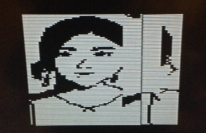
etcI decided to add some marker values at the start of the image:
rom_contents[5000] = 0x81;
rom_contents[5006] = 0xa1;
rom_contents[5012] = 0xc1;
rom_contents[5018] = 0xf1;
Then it was possible to attempt to see what was going on.
We can see that part way along the top line the 0xA1 (bin 1010 0001) marker can be seen, followed by the 0xC1 and 0xF1 markers, but the first 0x81 marker is missing. This implies to me that the code has somehow skipped the first byte of the image and then all subsequent bytes are 1 position out.
I think the issue could be related to the timing of the updating code which looks for the requested address changing from general ROM access to the special address 0xF00 (which actually comes out as 0xFF00 in the assembler, but is 0xF00 in the C code. The cartridge only has 12 bits as significant for the 2600 and they start at 0xF000). When the change is detected, i.e. the first write is being performed, the data value is sent out and then the index into the picture changes.
    if (address == 3840) {
        gpio_put_masked(8355840, rom_contents[img_pos] << 15);
if (last_address != 3840) {
img_pos++;
}
I think this means that there is only one read that results in the image data being written before it changes, so what I think might be happening is something like the following:
Atari Address                Pico Scanning
ROM address                  Returns ROM code
ROM address                  Returns ROM code
FF00                         Returns byte N from picture and updates picture index
FF00                         Returns byte N+1
FF00                         Returns byte N+1
ROM address                  Returns ROM code again
I don’t know how much of a problem this is, but I can see how the timing might be quite brittle if it does work.
I’ve changed the logic of the code to the following:
Setup:
  img_pos = 5000
  img_rom = rom_contents[img_pos]

Scanning Loop:
  IF (address == 0xF00) THEN
    Return img_rom value as the image data
  ELSE IF (last address == 0xF00 && address != 0xF00) THEN
    After last picture read, update index and store new img_rom value for next time
  ELSE
    Return ROM value
It is not perfect but when it all cycles round everything eventually seems fine. There does often seem to be one spurious read on power up which can put the whole first sequence out by a byte. In the end, I initialise the first img_pos pointer to 4999 rather than 5000. Once everything gets going it seems to work ok.
It is interesting that the interlacing is so visible on this modern TV. I can see why people seek out CRTs for their retro gear! Anyway, now the full first byte can be seen to be displayed correctly and then everything else follows.
I still don’t know if the issue is related to the PAL vs NTSC thing. I initially wondered that if the speed of the 2600 relative to the Pico is different, which I thought it would be when comparing 50Hz scanning to 60Hz, then maybe that means the original code isn’t so robust. Maybe at 60Hz the single address read is fast enough to get the right data byte, but at 50Hz it is slightly slower, meaning it is the changed byte that gets read instead.
But then I realised that the horizontal timing is the same for each, it is only the time it takes for the number of vertical lines that is different, so actually I don’t know what is going on. Maybe the clock in my old 2600 is slightly off. Or maybe the Pico isn’t overclocking reliably.
Either way, it seems a lot more robust for me with the update.
I am now wondering if I could add another special address location that could act as a sync between the Pico and 6502 which could be used to correctly signal the start of the frame.
Below are some of the various interim screens I ended up with whilst adjusting the assembler and Pico sequencing.
But I finally have a working picture frame app and have learned a lot about the Atari 2600 in the process.
There is a branch of the original project that contains all my messing around here: https://github.com/diyelectromusic/atari_2600_digital_frame/tree/kevins_learning
Update to the Build Process
One final additional update, I’ve now changed pico_rom.c to take the ROM and image data from two header files that are generated by the two provided python scripts.
The basic build process is now as follows:
- Use DASM to assemble the code for the Atari ROM.
- Use translate_bin2rom.py to create pico_rom_contents.h
- Use read_img.py to create up to four images in pico_rom_images.h
- Use cmake to create the build environment.
- Use make to build the final pico_rom.uf2 file for installing on the Pico.
This is all captured in a new build.sh file which builds four sample images from the img/for_display area and all of the above is now in my learning branch in GtHub.
There is one final build step I’ve not looked at – the magic file ‘slower_boot2_padded_checksummed.S” has some hex data in it that is build as part of the original picorom project. I might try to get that over at some point too, so the whole thing will build from source.
I’d also like to find out how to include the above python steps as part of the cmake/make process, but I don’t get on very well with cmake…
At some point I’d like to create an empty “how to build a Pico Atari ROM” project from all the above making it fairly easy to load and run homemade ROMs. There might even be an option for a future PicoW version that would support dynamic loading of a ROM binary file…
Kevin
#0 #15 #36 #44 #7 #atari #atari2600 #HEIGHT #picotari #raspberryPiPico


It's projects like this that give me hope for a new #Psion SSD based around the RP2350.
https://hackaday.com/2025/12/06/emulate-roms-at-12mhz-with-pico2-pio/
Client Info
Server: https://mastodon.social
Version: 2025.07
Repository: https://github.com/cyevgeniy/lmst