#HomeBuilt

TomKrajci πŸ‡ΊπŸ‡¦ πŸ³οΈβ€πŸŒˆ πŸ³οΈβ€βš§οΈKrajciTom@universeodon.com
2025-06-21

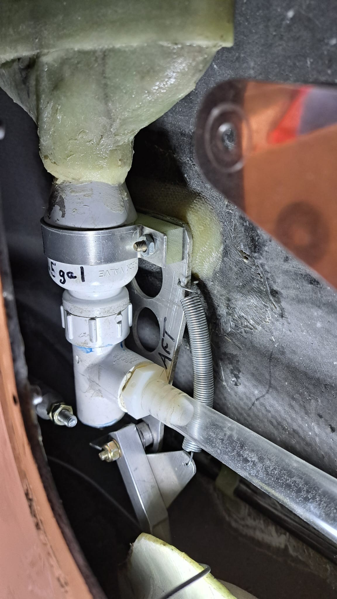
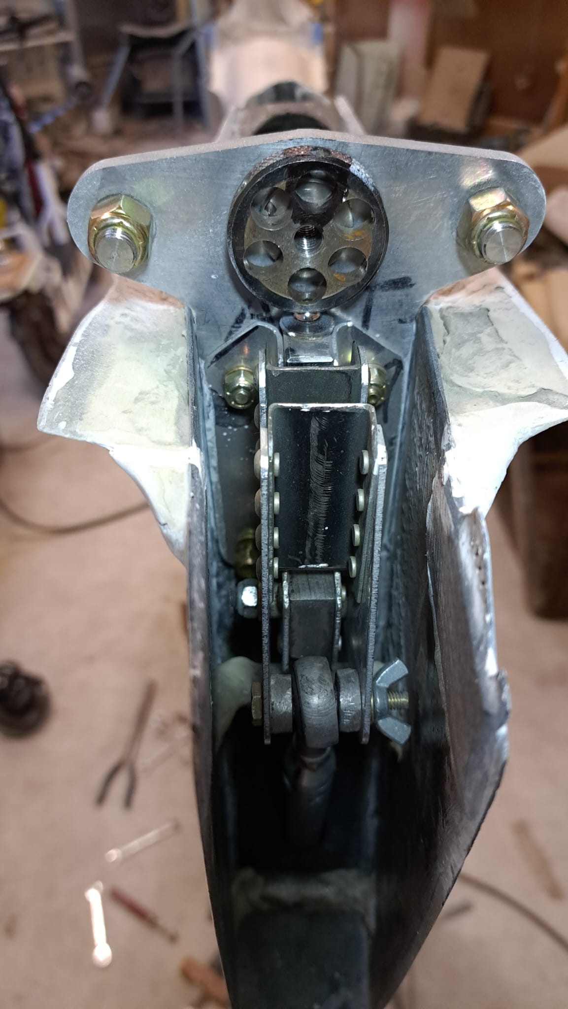
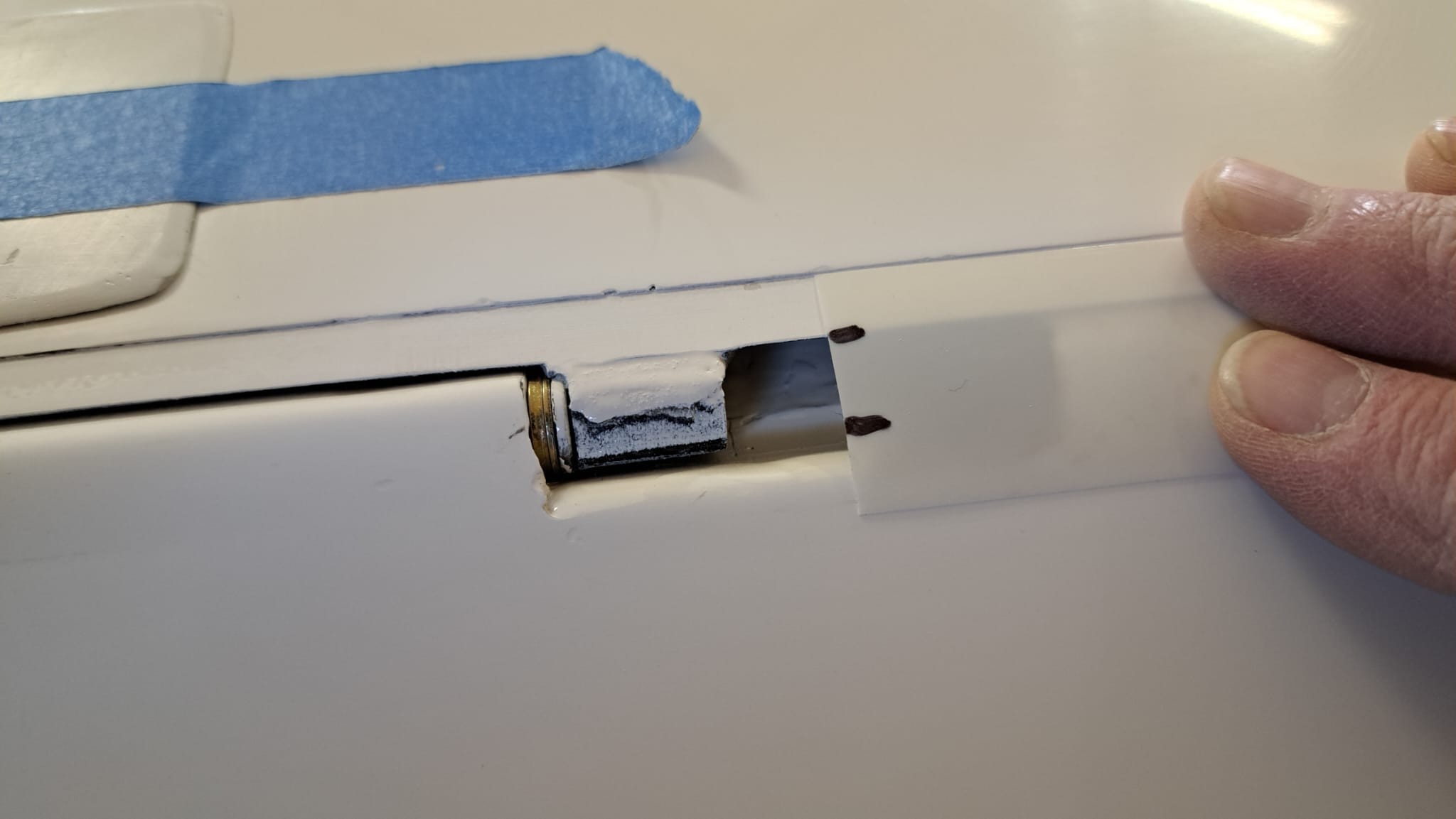
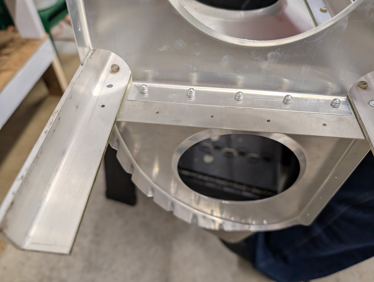
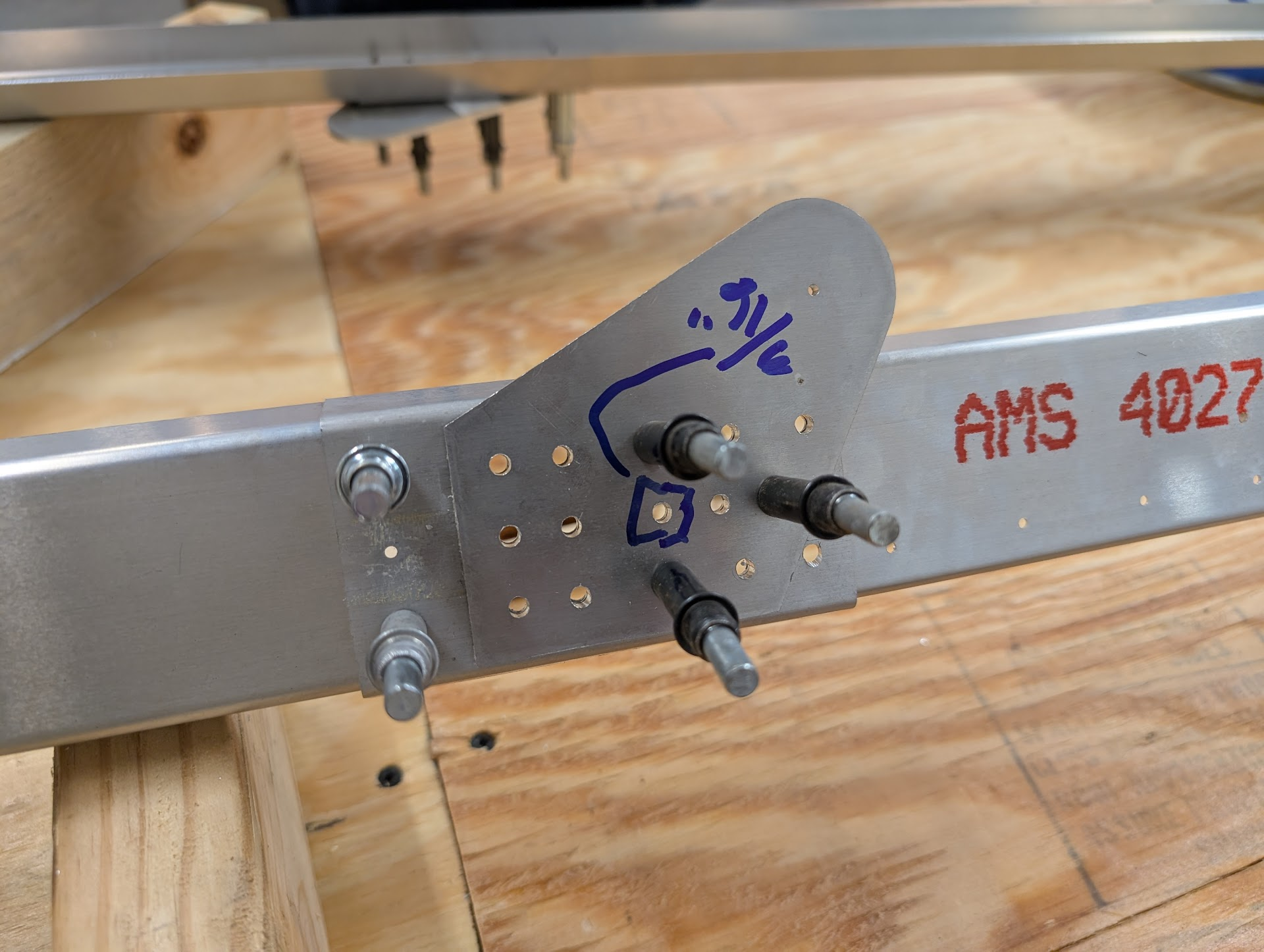
As I perform final assembly of various glider parts (landing gear, flight controls, etc.) I am replacing many temporary/keeper parts, such as nuts, and some bolts. (see photo)

The many silver-colored nuts (zinc plated) are ordinary hardware store parts. They are not locknuts.

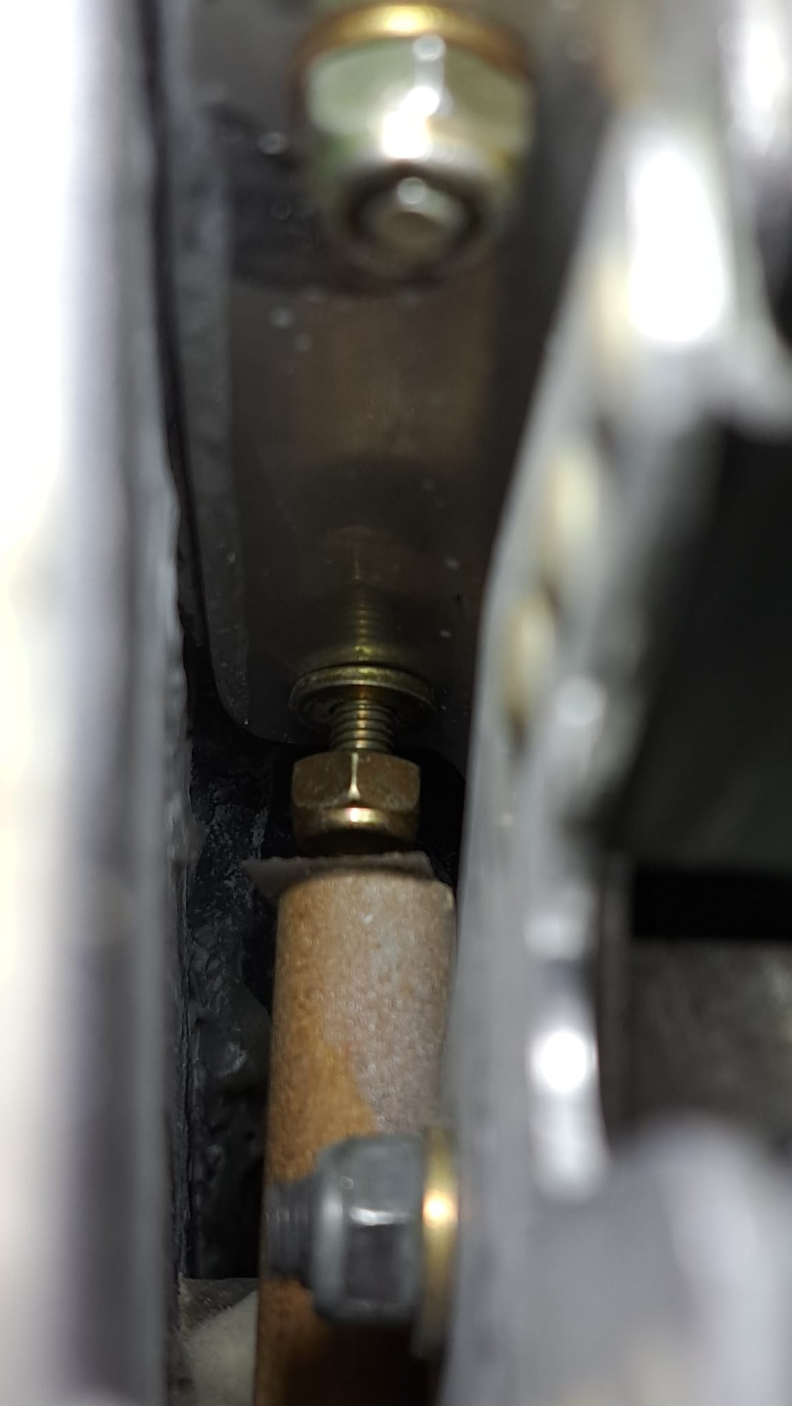
The few gold colored nuts (cadmium plated?) have a small rounded top where a nylon insert has been added. These are nylon lock nuts...nylocks. Those are the parts I want for most final assembly tasks. (Landing gear locknuts will use cotter pins or safety wire. They withstand greater shock loads and nylocks are insufficient.)

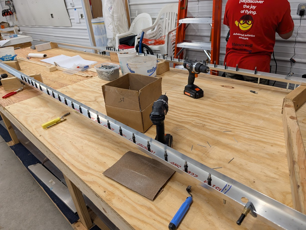
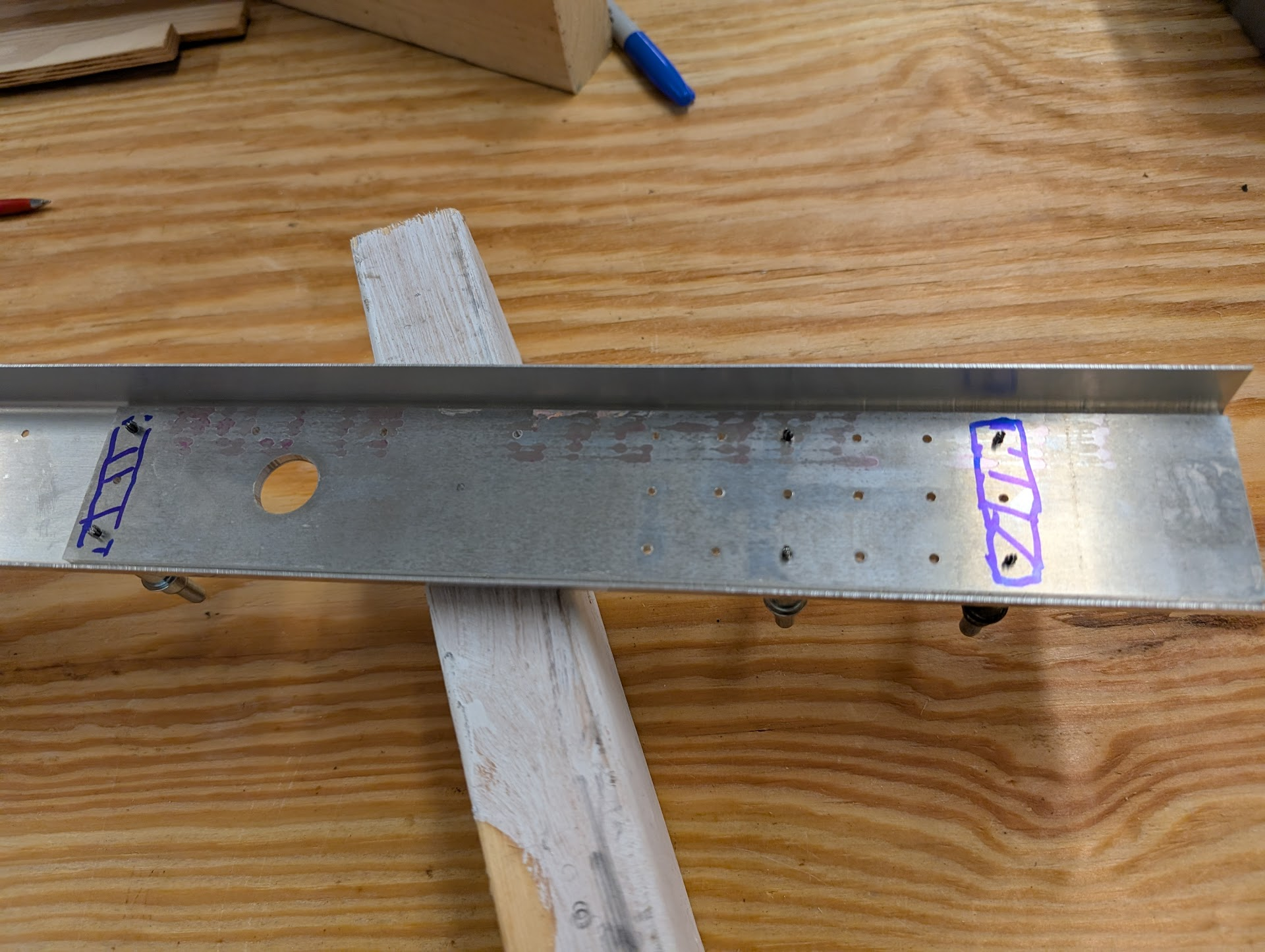
Note that some of the bolts in the photo are threaded along the entire length. Those are not suitable for connecting parts that are subject to shear loads. Instead, you want a bolt with a smooth shank. I am checking every bolt to make sure I have the correct shank length.)

#AvGeek #Aviation #ElectricAircraft #ExperimentalAviation #Homebuilt #Glider #DIY #Procedures #Nuts #Bolts

A collection of mostly hardware store nuts (silver colored), and a few aviation nuts and bolts (gold colored).

Choose your connectors carefully, especially if they are used in critical components.
TomKrajci πŸ‡ΊπŸ‡¦ πŸ³οΈβ€πŸŒˆ πŸ³οΈβ€βš§οΈKrajciTom@universeodon.com
2025-06-21

How do I attach the horizontal stabilizer and elevator to the vertical fin?

Now that I have finished all the parts, I can refine the procedure...where to stand, what gets placed first, second, etc.

This reminds me of an old saying in general aviation: There is a simple three-step procedure to start a warm engine. Unfortunately, nobody knows what it is.

#AvGeek #Aviation #ElectricAircraft #ExperimentalAviation #Homebuilt #Glider #DIY #Elevator #Procedures

Rachel Brindleyounata@hachyderm.io
2025-06-20

I want to build a contaminant box in my rv for things like a GATS jar, an oil rag, and other things I want to keep in the plane, but don’t want to mix with things like a backpack.
Maybe also including a section for actual trash.

Also on the topic of cabin upgrades, I want to add a water bladder hanging off the seatback, with the tube going to the front. I have a water bladder hanging off the back of my recumbent bike, and it’s great. So much better than a water bottle.

#avgeek #aviation #ExperimentalAviation #homebuilt

TomKrajci πŸ‡ΊπŸ‡¦ πŸ³οΈβ€πŸŒˆ πŸ³οΈβ€βš§οΈKrajciTom@universeodon.com
2025-06-17

The glider's tail water ballast tank has an outlet valve that fits 1/2-inch (13mm) I.D. tubing.

That can drain the tank in a matter of seconds.

The problem is that the far larger wing ballast tanks take five minutes to drain.

I want the tail tank to take five minutes to drain so that the C/G does not quickly shift while I'm dumping water.

I will probably add a small diameter flow constrictor to the outlet pipe. At this time I'm not sure of the final configuration, so I'm making two different versions of flow restrictors.

The thickened epoxy will need to be drilled to a small diameter (3/32 inch? 2.5mm?) in the left part, and the right part will need the brass bore to be drilled out to remove unwanted epoxy.

This is a follow up to:
universeodon.com/@KrajciTom/11

#AvGeek #Aviation #ElectricAircraft #ExperimentalAviation #Homebuilt #Glider #DIY #Tank #Tail #Epoxy #Ballast

Two test parts that will eventually become flow restrictors for my tail water ballast tank. 

Both parts are half of a hose (splicing) barb, filled with thickened epoxy. The right part has a smaller brass hose (splicing) barb placed inside.

The left part will need a small diameter hole drilled in the epoxy.

After the epoxy cures, the parts will be tested to see if they leak.
TomKrajci πŸ‡ΊπŸ‡¦ πŸ³οΈβ€πŸŒˆ πŸ³οΈβ€βš§οΈKrajciTom@universeodon.com
2025-06-16

The glider tail water ballast tank has been installed, but a few more things to do tomorrow.

First photo shows the tank being inserted through the top of the vertical fin. (You can't see the spring loaded dump valve, which is at the bottom of the tank.)

Second photo shows the bottom of the tank, which is bolted to one side of the vertical fin. You can also see pivoting valve trigger and return spring, and the dump hose.

Tomorrow I will crimp the end of the control cable.

The tank holds 1.5 gallons (5.7 litres) and is used to adjust the center of gravity location when the wing water ballast tanks are filled.

#AvGeek #Aviation #ElectricAircraft #ExperimentalAviation #Homebuilt #Glider #DIY #Tank #Tail

The tail water ballast tank is as tall as the vertical fin, and has an oval cross section. It looks slightly greenish because it's made of fiberglass.The bottom of the tank has a dump valve.

In order to do this installation, I had to remove most of the hardware for the elevator control linkage.
TomKrajci πŸ‡ΊπŸ‡¦ πŸ³οΈβ€πŸŒˆ πŸ³οΈβ€βš§οΈKrajciTom@universeodon.com
2025-06-15

Before I do more work at the tail end of the glider's fuselage (install the tail water ballast tank), I want to get most of the debris out of the tail boom. When I rotate the fuselage, it sounds like a pair of maracas.

I have an access hole in the aft battery box bulkhead, so I connected the shop vac hose to the exhaust side...to get all the air moving out of the tail boom at a good clip, then inserted the compressor hose at 100PSI to knock debris loose and give it a kick.

#AvGeek #Aviation #ElectricAircraft #ExperimentalAviation #Homebuilt #Glider #DIY #Vacuum #Compressor #Dust #Clean

Looking at the tail boom from the forward end. The battery box door has been removed and a wide diameter, low pressure air hose has been inserted into the tail boom. I'm holding an air compressor hose fitting that blasts high pressure air...in order to loosen debris inside the tail boom. This, hopefully, will remove most of the debris from the tail boom.
TomKrajci πŸ‡ΊπŸ‡¦ πŸ³οΈβ€πŸŒˆ πŸ³οΈβ€βš§οΈKrajciTom@universeodon.com
2025-06-15

Final assembly of glider parts means working in very cramped, awkward spaces.

I often have to improvise tools or modify existing ones.

First photo shows a wooden dowel with double sided tape on the end. It was used to start a nut on a bolt.

Second photo shows the top of the vertical fin, aft end, looking forward. The aluminum 'dog bone' is bolted to the fin spar (carbon fiber), and the elevator auto-connect fork (and its bracket) are also bolted to the dog bone.

Last photo shows some of the tools of the trade. From the top, then going clockwise:
- wooden dowel and double sided tape
- small mirror on telescoping shaft and multi-axis pivot
- magnet on telescoping shaft
- box end wrench with the outer surfaces of the jaws ground away
- socket (ground to a smaller outer diameter) on a hand driver
- flexible four-finger 'picker upper' to retrieve dropped parts

#AvGeek #Aviation #ElectricAircraft #ExperimentalAviation #Homebuilt #Glider #DIY #Tools

A wooden dowel with double sided tape on the end. It was used to start a nut on a bolt.The top of the vertical fin, aft end, looking forward. The aluminum 'dog bone' is bolted to the fin spar (carbon fiber), and the elevator auto-connect fork (and its bracket) are also bolted to the dog bone.Some of the tools of the trade. From the top, then going clockwise:
- wooden dowel and double sided tape
- small mirror on telescoping shaft and multi-axis pivot
- magnet on telescoping shaft
- box end wrench with the outer surfaces of the jaws ground away
- socket (ground to a smaller outer diameter) on a hand driver
- flexible four-finger 'picker upper' to retrieve dropped parts
TomKrajci πŸ‡ΊπŸ‡¦ πŸ³οΈβ€πŸŒˆ πŸ³οΈβ€βš§οΈKrajciTom@universeodon.com
2025-06-14

My elevators on the horizontal stabilizer (my black-gloved hand is touching them) need mass balance to minimize flutter at high speed.

My rudder, also in 1st photo, has the mass balance built into it. There is not enough room to do that for the elevators.

Where to put the mass balance?

The oval hole at the bottom of the vertical fin is an access/inspection point. It goes there.

Note: when the mass balance is 'far away' from the control surface, the control system linking the two should have as little slop (backlash, hysteresis) as possible.
en.wikipedia.org/wiki/Backlash
en.wikipedia.org/wiki/Hysteres

The counterweight is lead shot in thickened epoxy. (I won't melt and cast molten lead!)

The density of lead shot?
en.wikipedia.org/wiki/Sphere_p

Read alt-text for more info.

Info on mass balancing, and a view of my rudder with its integral chunk of lead:
universeodon.com/@KrajciTom/11

#AvGeek #Aviation #ElectricAircraft #ExperimentalAviation #Homebuilt #Glider #DIY #Balance #Flutter #Engineering #Math

My gloved hand is touching the elevators. They need mass balancing to control flutter, but they are smaller than the big rudder. What to do?

Put the mass balance some distance away, on the control linkage.

See the oval hole in the vertical fin at the bottom? That's where it will go.

See the next photo....We are looking into the oval access/inspection port in the lower part of the vertical fin. The mass balance looks like a large disk. To its right is a push-pull tube that runs up to the elevator. Below the mass balance is the end of a (very long) push-pull tube that comes from the cockpit and control stick. I have disconnected this part because it is not important in determining the mass...which I determined by trial and error with pieces of scrap steel.

I refuse to melt and cast molten lead. Fortunately, I could make a heavy enough disk of lead shot and epoxy that was small enough to allow proper operation.

The density of lead? Easy...search engine or engineering book.

The density of epoxy? Read the documentation.

The density of a randomly packed bunch of spheres? Learn about sphere packing:
https://en.wikipedia.org/wiki/Sphere_packing

I used 66% as the packing value.

The two 'leaves' of the bell crank are spaced 7/8 inch apart. That constrains my disk thickness. OK, what diameter? Simple spreadsheet math...check the available room...OK, I can do this.

Make a circular mold from scrap wood. (Destroy the mold when demolding...one-shot use, no big deal.)

When molding the lead shot and epoxy...next time, use epoxy with less thickening agent so that its lower viscosity.

The disk ended up a bit thicker than planned...about 1/16th inch (1.5 mm).

What to do? Next picture....Lead and epoxy are easy to machine. I don't have a mill, but I cut the end off a drill bit and reground it to make a crude end mill. Hand force was all I needed to do the machining of the recessed area.

Bonus: the recessed area also serves as a constraint against the disk spinning around over time.
TomKrajci πŸ‡ΊπŸ‡¦ πŸ³οΈβ€πŸŒˆ πŸ³οΈβ€βš§οΈKrajciTom@universeodon.com
2025-06-13

Do the rudder and elevator interfere with each other at the extremes of their movement?

I think I have a little bit more sanding to do because I was able to increase the rudder deflection a little bit. Now it can get very close to the elevator.

#AvGeek #Aviation #ElectricAircraft #ExperimentalAviation #Homebuilt #Glider #DIY #Drag #Aerodynamics #CarbonFiber #Rudder #Elevator #Interference

TomKrajci πŸ‡ΊπŸ‡¦ πŸ³οΈβ€πŸŒˆ πŸ³οΈβ€βš§οΈKrajciTom@universeodon.com
2025-06-13

What size mylar strip do I need to cover the various control surface gaps?

This is the elevator, full down position. I need a 30mm wide mylar strip to cover it.

The mylar strip will be cut to length and taped in place.

The rudder and flaperons may need different width mylar strips.

All of this drag reduction should boost my cruising speed by 0.01 knots.

#AvGeek #Aviation #ElectricAircraft #ExperimentalAviation #Homebuilt #Glider #DIY #Drag #Aerodynamics #Slick #CarbonFiber

The control surface gap (horizontal stabilizer and pivoting elevator) needs to be covered with a mylar strip to reduce drag and improve aerodynamics. I am determining what width strip I need.
TomKrajci πŸ‡ΊπŸ‡¦ πŸ³οΈβ€πŸŒˆ πŸ³οΈβ€βš§οΈKrajciTom@universeodon.com
2025-06-06

The glider fuselage has been wet sanded.

It's time to for final buffing.

I did some experimenting this morning to get a feel for process and especially process control.

I had two different polishing pads. Would they give different finish quality?

Would a grid of black Sharpie help me keep track of buffing progress?

(Don't worry about the Sharpie. It doesn't stain the polyurethane paint. I can wipe it away with a solvent like acetone.)

Either polishing pad gives similar results, and buffing until the Sharpie grid is gone appears to be a workable control technique.

Water beading on the buffed surface is another indication of progress.

On areas with complex, and especially concave curvature, I'll buff by hand.

I'm not trying to do a fantastic job on the fuselage, but I'll gain experience before I do the critical stuff: the wings.

#AvGeek #Aviation #ElectricAircraft #ExperimentalAviation #Homebuilt #Glider #DIY #Paint #Sand #Buff #Polish

The initial experiment setup. Two small Sharpie grids on the belly of the fuselage.

Buff one of the grids with one of the polishing pads...but don't remove all the Sharpie on the first grid....I was surprised that it didn't take that long, or that much pressure to remove most of the Sharpie grid.

Once I cleaned up this area, I saw that it had an acceptable finish quality.Here is another indicator of buffing progress: water beading on the surface when it's sufficiently buffed.Both polishing pads produced similar finish quality. 

I think the Sharpie grid is a decent tool to show buffing progress.

Now I just need to put in the hours....
2025-06-05

Yesterday evening was my EAA Chapter's build night for our Zenith kit. Some of us went about drilling the final holes for the wing ribs and riveting them while the other members were in the process of preparing the rear spar for the wing. While we were working a very heavy rain storm hit (just in time to soak the grass runway that just dried out).

#generalAviation #experimentalAviation #eaa #kitplane #homebuilt #avgeek #aviation

Outboard edge of left wing showing the rivets holding the ribs to the spar.Mostly full view of wing spar with ribs attachedTwo rear spars (both wings) on a work bench. Clecos line the spar as holes are being prepared for rivets.Outdoor picture of a rain soaked apron at an airport. Clouds overhead and hangars are visible going off into the distance. The grass runway is cut nicely but given the puddles on the apron it is definitely hiding some water.
TomKrajci πŸ‡ΊπŸ‡¦ πŸ³οΈβ€πŸŒˆ πŸ³οΈβ€βš§οΈKrajciTom@universeodon.com
2025-06-02

The glider fuselage paint job has been scraped to remove drips and runs, and also to cut off the top of all the orange peel bumps that cover the entire surface.

I had to experiment with making a scraper tool. It required constant sharpening.

I have transitioned to wet sanding with a dual action polisher to remove the rest of the orange peel, but I had to experiment a bit to get a process and system. That's because I can't see the progress of sanding of a white surface that's covered with sanding water sludge. I will probably draw a grid of lines over the fuselage that allow me to monitor progress.

The final photo shows light at a glancing angle across a sanded test patch (fuselage belly...I don't mind screwing up here). I see no signs of orange peel, or larger ripples/waviness.

I think I can transition from this sanding job directly to rubbing and polishing compound.

#AvGeek #Aviation #ElectricAircraft #ExperimentalAviation #Homebuilt #Glider #DIY #Paint #Sand #Buff #Polish

Testing various pieces of hardened steel to make a scraper that removes the tops of all the orange peel bumps. Some metal could not take or hold an edge well.Glancing light shows that the vertical fin on the fuselage has been scraped all over. The tops of orange peel bumps have been removed.I need to draw black lines on the fuselage to easily monitor sanding progress. When the lines are gone, I have sanded enough.Low angle light shows a uniform surface with no small-scale orange peel, or larger scale waviness or ripples. This is a good sign.
TomKrajci πŸ‡ΊπŸ‡¦ πŸ³οΈβ€πŸŒˆ πŸ³οΈβ€βš§οΈKrajciTom@universeodon.com
2025-05-20

My glider needs a tug that can pull it from the landing spot to the transport trailer or hangar.

That distance may be over a mile at larger airfields.

Glider clubs often use electric golf carts, but those are expensive and way too big for the task. I need a rig that can easily be put in the bed of my truck.

An electric scooter?

Some of them have larger tires, more powerful motors, a larger payload capacity.

Today I tested this model:
isinwheel.com/products/isinwhe

I measured the static pull...about 40 pounds of force.

That is plenty for pulling a 600 pound glider when you consider that rolling friction is about 1/50th of a vehicle's weight. That comes to 12 pounds.

I don't need high speed. You tow at a fast walk or slow jog.

I don't need dozens of miles of range.

And it's fun to ride.

Need more power for a heavy two-seat glider?
isinwheel.com/products/isinwhe

#avgeek #aviation #ElectricAircraft #ExperimentalAviation #homebuilt
#Glider #DIY #Scooter #eScooter #EV #ElectricScooter

An eScooter with a scale on the back end, connected to a rope that's connected to a fixed anchor (not in photo). This setup allows me to measure the towing force of the eScooter.
2025-05-14

We are SO back.

Tuesday build night at the EAA Chapter Hangar. We sold off the Murphy Rebel kit and continue the work on our Zenith kit. I spend most of the time digging out some mislabeled parts. This will be the rear spar on the wing and it requires some reinforcement. I eventually found everything, got it oriented as expected, and drilled some holes. We've been bitten so many times by rushing we had three people going over the plans and confirming the actions before I drilled the holes up to size (hope we did it right).

#kitplane #zenith #experimentalAviation #eaa #aviation #avgeek #airplane #homebuilt

Technical drawing detailing the rivets, holes, parts, and spacing for rear spar reinforcement on the wing.Rear spar where the two parts meet. It has a reinforcement bracket to splice it together and then a thick doubler plate to make it stronger. All the holes were drilled to #20 and one hole is marked to be upsized again to 3/16"Doubler plate laying inside a spar part for the root of the wing. Two rows of holes have been marked off as a reminder to NOT drill them.
TomKrajci πŸ‡ΊπŸ‡¦ πŸ³οΈβ€πŸŒˆ πŸ³οΈβ€βš§οΈKrajciTom@universeodon.com
2025-05-10

Glider rudders need a counterweight to be properly balanced.

What?! Aren't airplanes supposed to be light? Why add more weight?

This reduces the tendency toward flutter. (Any airplane, at a high enough speed, will flutter. Don't go that fast.)

An unbalanced rudder (or any flight control surface) will be prone to flutter at slower speeds.

1st photo shows the rudder on a bracket that allows the rudder to freely pivot. (See alt text for more discussion.)

2nd photo shows rudder oriented normally. (See alt text)

en.wikipedia.org/wiki/Aeroelas

Imagine being the test pilot here...deliberately gaining speed to get (just barely) into the flutter regime...surviving, and learning.
youtube.com/watch?v=kQI3AWpTWh

I am not using a control horn to reduce the control pressure I feel on the rudder pedals. Modern gliders typically don't need that.

en.wikipedia.org/wiki/Flight_c

en.wikipedia.org/wiki/Balanced

#AvGeek #Aviation #ElectricAircraft #ExperimentalAviation #Homebuilt #Glider #DIY #Balance #Flutter #Engineering

The rudder is free to pivot on this bracket.

The counterweight mass has shifted the center of gravity a bit forward of the pivot axis, so the trailing edge swings up and the counterweight swings to the bottom.

If there were no counterweight mass on this rudder, the trailing edge would drop to the lowest position. But this is not desirable, in terms of center of gravity location, to minimize vulnerability to flutter. So, we add the counterweight.

But how much mass? Enough to balance the rudder on the pivot axis in a static test?

Or do we need to consider other forces in a dynamic test? (See next photo....)With the rudder oriented normally I can grab the bracket and accelerate the rudder side-to-side.

That acceleration creates inertial forces...center of gravity...counterweight helping locate the C/G, etc. But we are moving through the air and that rudder has considerable surface area...so, now we are adding aerodynamic forces into this test. (The static balance test does not involve aerodynamic forces.)

With the current counterweight, when I accelerate the rudder side-to-side...the heading/pointing of the rudder stays roughly constant. There is a rough balance between the aerodynamic forces that want to pivot the rudder one way, and the counterweight's forward shift of the C/G that wants to pivot the rudder the other way.

Is this the correct amount of counterbalance for the rudder?

For an amateur project, that is very difficult to model and predict. (It's difficult for the pro's with highly engineered designs.) Live testing in flight will be the final arbiter.
TomKrajci πŸ‡ΊπŸ‡¦ πŸ³οΈβ€πŸŒˆ πŸ³οΈβ€βš§οΈKrajciTom@universeodon.com
2025-05-08

I needed to mix a small bottle of nail polish to which I had added some acetone in order to thin the paint somewhat. This was a perfect job for my large paint shaker.

I needed thinner paint for some touch-up work at the exhaust port on the glider's turtle deck.

See next two comments to this post....

#AvGeek #Aviation #ElectricAircraft #ExperimentalAviation #Homebuilt #Glider #DIY #Paint #Sand #Buff #Polish

TomKrajci πŸ‡ΊπŸ‡¦ πŸ³οΈβ€πŸŒˆ πŸ³οΈβ€βš§οΈKrajciTom@universeodon.com
2025-05-05

One 12-foot section (3.6 meters) of flaperon has been sanded, buffed, and polished.

Three more to go....

Flaperon? It's both a flap and an aileron.

en.wikipedia.org/wiki/Flaperon

en.wikipedia.org/wiki/Flap_(ae

en.wikipedia.org/wiki/Aileron

#avgeek #aviation #ElectricAircraft #ExperimentalAviation #homebuilt
#Glider #DIY #Paint #Sand #Buff #Polish

The white flaperon, 12 feet long, sits on a padded work surface inside a garage workshop. Its white paint has been buffed and polished. An orange/yellow polishing rag sits on the flaperon. In front of the polishing rag is the drive horn that will be connected to a push-pull rod that is part of the flight control mechanical linkage.
TomKrajci πŸ‡ΊπŸ‡¦ πŸ³οΈβ€πŸŒˆ πŸ³οΈβ€βš§οΈKrajciTom@universeodon.com
2025-04-29

The glider's horizontal stabilizer's paint needs scraping to remove runs and drips.

This part has a span of eight feet (2.44 meters). And I need to work on both sides.

Fortunately, the surface is convex, or flat in various locations...but it's happily not concave.

Setting up the work lights to give me specular reflections makes it easy to see and then work on the drips and runs.

I'm also learning that how I sharpen/sand the razor's edge (symmetric? asymmetric?), how I hold it (rake angle)...can make a big difference in how efficiently and effectively I can scrape away the high spots.
en.wikipedia.org/wiki/Rake_ang

The pile of shaved paint next to the razor was produced with one gentle pass...once I started figuring out sharpening geometry and rake angle. Before that, my progress was slow and required much more effort.

#avgeek #aviation #ElectricAircraft #ExperimentalAviation #homebuilt
#Glider #DIY #Paint #Sand #Buff #Polish @jivens

Glider horizontal stabilizer on sawhorses. A single edge razor sits on the stabilizer.Specular reflections show me many runs and drips that I will scrape down to match the surrounding surface.

(Reflections also show me orange peel...the bane of my existence.)Careful, gentle scraping can remove lots of high paint in one pass. The pile of shavings was made in one pass with little effort.Sanding/sharpening the razor-scraper. This is 400 grit sandpaper.

Client Info

Server: https://mastodon.social
Version: 2025.04
Repository: https://github.com/cyevgeniy/lmst