MiniDexed EuroRack PCB Build Guide
Here are the build notes for my MiniDexed EuroRack PCB Design.
This is a DIY module only for use in my own DIY system.
Do NOT use this alongside expensive modules in an expensive rack. It is highly likely to cause problems with your power supply and could even damage your other modules.
Warning! I strongly recommend using old or second hand equipment for your experiments. I am not responsible for any damage to expensive instruments!
If you are new to single board computers, see the Getting Started pages.
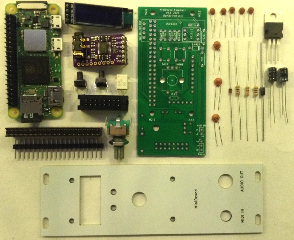
Bill of Materials
- MiniDexed EuroRack PCB (GitHub link below)
- Front panel
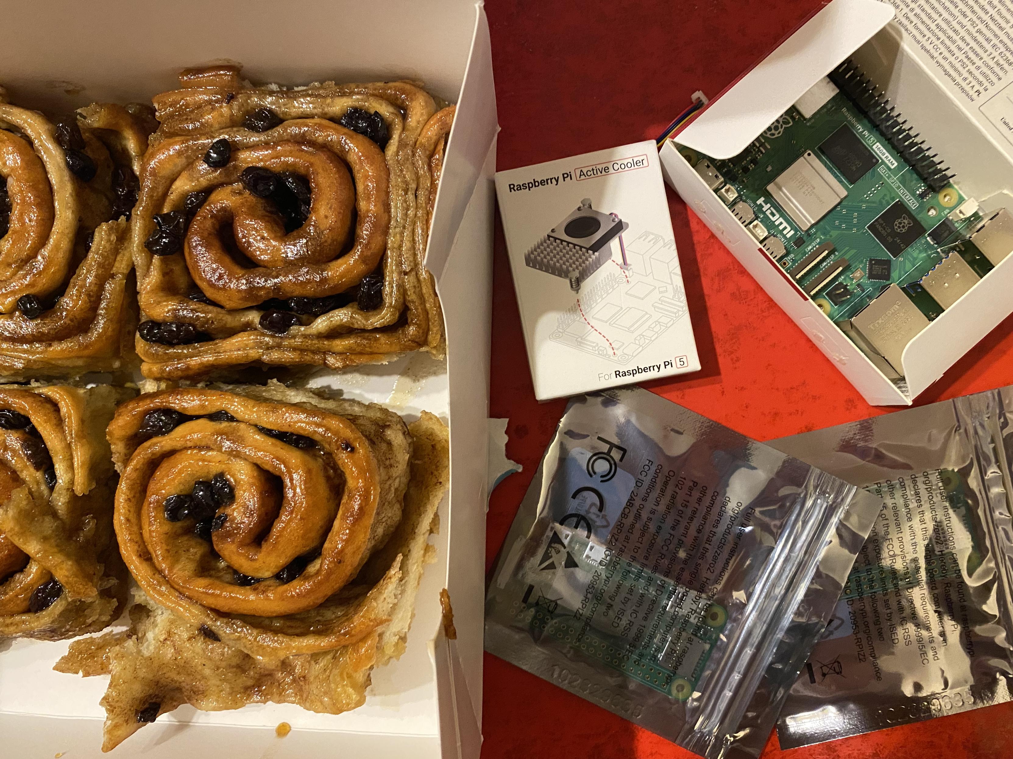
- Raspberry Pi Zero (1 or 2)
- GY-PCM5102 module
- 128×32 SSD1306 OLED display module (pins order: GND-VCC-SCL-SDA)
- 1x L7805 regulator
- 1x H11L1 optoisolator
- 1x 1N5817 Schottky diode
- 1x 1N4148 or 1N914 signal diode
- 1×220Ω, 1×470Ω resistors
- 5x 10nF ceramic capactiors
- 3x 100nF ceramic capacitors
- 2x 47uF electrolytic capacitors (low profile if possible – see text)
- 1x switched rotary encoder with a threaded shroud and nut
- 2x tall tactile buttons – 6x6mm base, at least 12mm height (it needs to poke through the panel!)
- 16-way shrouded EuroRack style power header.
- 40-way GPIO header (optional: extended – see discussion).
- Pin-headers and connecting wires.
Also required: 3.5mm panel mount sockets for audio and MIDI – I use different types, but it will depend on the panel used (see panel discussion).
Build Steps
Taking a typical “low to high” soldering approach, this is the suggested order of assembly:
- Resistors and diode on the top.
- H11L1 (assuming soldered directly to the PCB).
- Disc capacitors on the top.
- Diode and disc capacitor on the bottom.
- Electrolytic capacitors on the bottom.
- GPIO and 16-way power socket on the bottom.
- Buttons and encoder on the top.
- GY-PCM5102 module (see photos for steps required prior to fixing).
- SSD1306 (see photos for steps required prior to fixing).
Here are some build photos and more details of the steps involved.
Note: Most of these photos show the build for V0.1 of the PCB. There are some minor updates in V0.2 which will be noted where relevant.
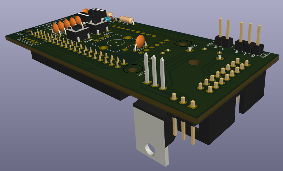
The power circuit on the underside of the board has two options for mounting the regulator. It can go either vertically or horizontally, but with the tab up. Both methods use the same solder holes. Which is chosen will largely depend on what heatsink options there are.
Note: the first version of the board only had a single option, with the tab down, making contact with the PCB. This didn’t really work from a cooling perspective, hence the change.
The following “in progress” photos still show the first version of the board with the regulator the other way around, an additional resistor, omitted from V2, and the diode in a different place.
Note that low-profile capacitors may be required as they will sit underneath the Raspberry Pi Zero. If the regulator is “standing up” then it should be possible to bend the capacitors over into the space reserved for the regulator.
The GPIO headers have to allow enough space for the Zero to be mounted and not interfere with the PCM5102. See discussion below.
The EuroRack headers need to be correctly oriented and shrouded headers are strongly recommended.
The SSD1306 requires additional spacers on the pins to raise it above the PCB for presentation closer to the front panel.
The PCM5102 must have its solder jumpers configured, if not set already, and requires both sets of pin headers adding.
In the photo below, the PCM5102 has zero-ohm, surface mount resistors as jumpers – but it is really hard to see! On first glance, it looks like there is no link configured at all, but they are connected as: 1L, 2L, 3H, 4L.
These modules have to be added after the other components, as they prevent access to the solder pads during assembly.
GPIO Header Options
One option is to use extended headers, which ought to allow room for the Zero and a heatsink (if required) on the main BCM chip. Note: A V2 Pi Zero could probably benefit from a heatsink I’d imagine if running fully processing all 8 tone generators.
Another option is to remove the on-board 3.5mm, SMT, audio jack on the PCM5102 as shown below, and use “normal” sized GPIO headers.
If non-extended GPIO header is used then, as already mentioned, low-profile electrolytic capacitors may be required as they are positioned underneath the Pi Zero too.
Power Options
As previously mentioned, there wasn’t really much choice when it came to mounting the power regulator for V1 of the board, but in V2 I’ve positioned it differently to allow it to be “tab up” or upright.
The upright positioning was hopefully placed so that a long, thin heatsink could be mounted alongside the Pi. This shows one of those heatsinks you can get for M2 SSD cards. I figure that drilling a hole in it would do the trick, but I’ve not actually done this myself (see below).
The solution I went with in the end was to actually replace the 7805 with a 7805-compatible DC-DC buck converter. These are available fairly cheaply online.
These work a lot more efficiently than a 7805, so especially when drawing 300mA or so from a Pi Zero 2 whilst dropping from 12V down to 5V, they still have no need of a heatsink.
The downside of using these (apparently) is that as a switching power unit, they can be pretty electrically noisy. But as I’m powering a microcontroller rather than a pure analog circuit in the first place, I decided it probably wasn’t going to be making things much worse. This is hardly a high quality, electrically clean build anyway!
Final Assembly
Required Components to use my panel:
- MiniDexed EuroRack Panel (see Github link below).
- Raspberry Pi Zero (1 or 2) with GPIO header pins.
- MiniDexed EuroRack PCB as described above.
- Panel mount 3.5mm TRS socket for MIDI. 6mm diameter hole assumed.
- Panel mount 3.5mm TRS socket for audio. 8mm diameter hole assumed.
- 2.5mm mounting posts, screws and nuts.
I’m using the same designs of TRS sockets for MIDI and audio that I use in all my modules. These need mounting on the panel. Soldering will come in a moment.
I found that with the GPIO header height I was using, alongside the final height of the SSD1306, height of the buttons, and the encoder’s shroud, that the following mountings were required:
- 2x black nylon 2.5mm 6mm screws
- 2x black 10mm 2.5mm spacers
- 2x white 8mm 2.5mm spacers with screws
- 2x white nylon 2.5mm 6mm screws
An alternative build had a slightly larger gap (due to using 12mm buttons) so required four sets of 10×2.5mm spacers.
Another quirk of my first build was that I only had 9mm high buttons which wasn’t quite enough to reach through the panel. Ideally a 11mm or larger button would be required.
But this allowed me to 3D print a white 2.8mm diameter, 3.0mm high, extension that I could glue on the top, meaning that the exposed part of the button was white, matching the panel.
My second build used a black panel and 12mm buttons, but as already mentioned this meant the panel had to use 10mm spacers instead of 8mm spacers. One issue with that is that there isn’t much of the encoder shaft exposed. I found some knobs that worked ok, but my preferred (cheap) knobs could not be fitted and still allow the encoder switch to function.
In summary, there is still a fair bit of trial and error with each build depending on the exact combinations of screen height, encoder shaft length, button length and so on.
Once the PCB and panel is fixed together then the two 3.5mm sockets can be soldered to the PCB (or connected using headers if that was the preferred option).
Recall that MIDI IN does not required a GND connection. Also double check which solder tabs correspond to the TIP and which to the RING, which should match the “T” and “R” labels on the PCB (“S” is for shield, i.e. GND).
Testing
I recommend performing the general tests described here: PCBs.
Then, prior to plugging in the RPi Zero, do the following:
- Verify that the 12V and GND connections of the EuroRack connector have no shorts.
- Power up the board (no Pi) and verify that there is a 5V signal present and going to the PCM5102 and SSD1306. The PCM5102 should have its red power LED on.
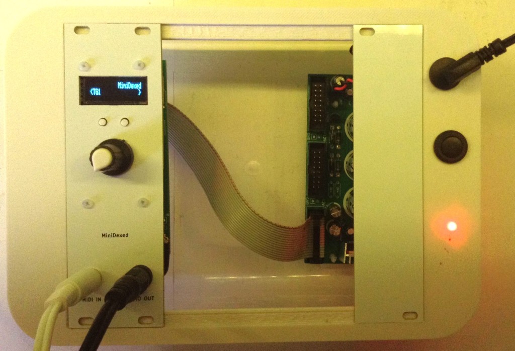
Only then power off, plug in the RPi Zero with an SD card containing MiniDexed (configuration below) and verify that the display, encoder, buttons, MIDI IN, and audio out are all working.
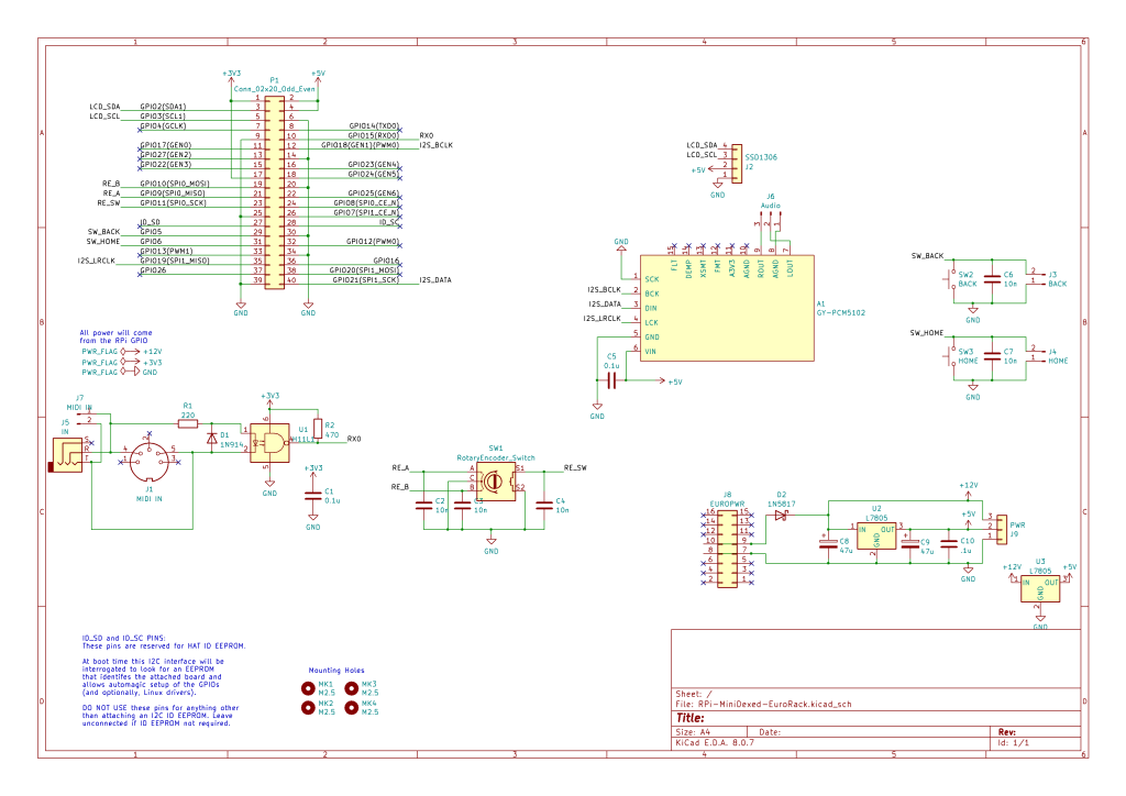
MiniDexed Configuration
The following are the key MiniDexed.ini configuration options required:
SoundDevice=i2s

SSD1306LCDI2CAddress=0x3C
SSD1306LCDWidth=128
SSD1306LCDHeight=32
LCDColumns=20
LCDRows=2

ButtonPinBack=5
ButtonActionBack=click
ButtonPinSelect=11
ButtonActionSelect=click
ButtonPinHome=6
ButtonActionHome=click
ButtonPinShortcut=11

EncoderEnabled=1
EncoderPinClock=10
EncoderPinData=9
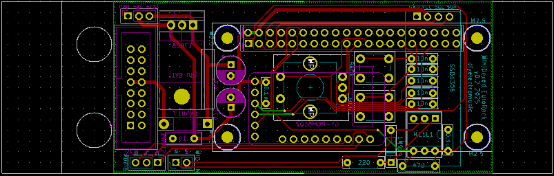
PCB Errata
As already noted, there were a number of issues with the first version of the PCB, but these should have been addressed in the published version.
As the time of writing, there are no further known issues with V0.2 of the PCB.
Enhancements:
- I feel like the power situation ought to be better. One option could be to break out a USB connection to the Zero directly allowing the use of a standard “wall wart” type supply.
- Another option might be to make use of the solder pads on the rear of a Zero (like the Zero STEM does).
- It might also be useful to provide a configurable (e.g. solder bridge) link to enable the EuroRack +5V supply as an option.
- There are already options to use internal (within a rack) links for MIDI and audio if required using the pin headers on the PCB, but it might be nice to allow a choice between panel or rear connectors.
Find it on GitHub here.
Closing Thoughts
I’m still not fully happy with the longer-term implications of how I’m powering these boards, but I’ll see how things go. Those DC-DC converters seem like a feasible option so I’ll see how they perform.
The panel height issue could be better too – it would be nice to have a recommended set of components and a known useful size of spacers, but there is still a fair bit of trial an error at the moment with each build.
Also, sometimes the display height isn’t perfect, as shown below. I might 3D print a display bezel or surround to help.
The end results looks pretty good though, so for this stage in my thinking about these, I’m pretty pleased with how this has ended up.
But one last time, just to make my position totally clear: this is a DIY system and should only be used with other DIY modules you wouldn’t mind too much losing.
It is NOT for use alongside other commercial (expensive) or treasured modules. There are commercial versions of MiniDexed apparently for that, that I have no experience of.
Kevin
#EuroRack #midi #minidexed #pcb #RaspberryPiZero