#minidexed

Simple DIY Electronic Music Projectsdiyelectromusic.com@diyelectromusic.com
2025-05-03

picoDexed + MiniDexed EuroRack

Since attempting my picoDexed + StackyPi + MiniDexed EuroRack build and failing, I’ve found another Pico-to-Zero board that is provided as open source, so I’ve had some made.

This post details how to get that running with my MiniDexed Zero Eurorack module.

Warning! I strongly recommend using old or second hand equipment for your experiments.  I am not responsible for any damage to expensive instruments!

If you are new to microcontrollers and single board computers, see the Getting Started pages.

Pi Zero RP2040s

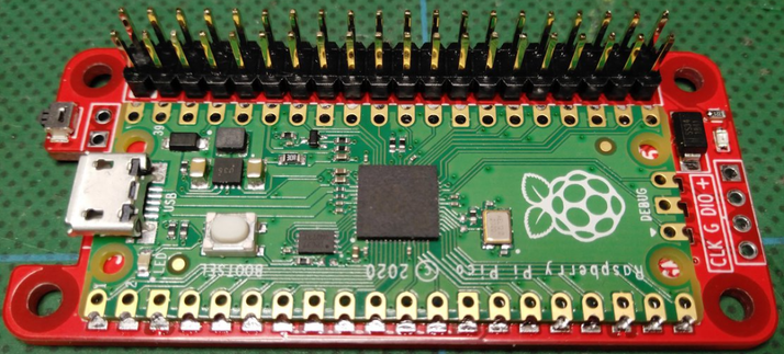
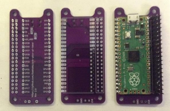
As mentioned last time I found a number of options for a RP2040 based dev board in a Raspberry Pi Zero form factor. But this post is about this one:

It is fairly simple to build. It just requires a Pico and GPIO header pins.

There is an option for pull-ups on the I2C bus, but I’ve not bothered with them here. There is also a breakout header for a reset switch if required (it will support two sizes of switch by the looks of things).

Mapping over to MiniDexed/RPi Zero

The pinout is slightly different to the Stacky-pi, so here is an updated table of the GPIO mappings and which are required to be used with my MiniDexed board.

RP2040UseRPiRpiUseRP20403V35VGP2LCD SDAGP2 SDA5VGP3LCD SCLGP3 SCLGNDGP4GP4GP14 TXDGP0GNDGP15 RXDMIDI INGP1GP5GP17GP18I2S BCLKGP18GP6GP27GNDGP7GP22GP23GP83V3GP24GP28GP11RE BGP10 MOSIGNDGP12RE AGP9 MISOGP25GP27GP10RE SWGP11 SCLKGP8GP9GNDGP7GP26ID_SDID_SCGP22SW BACKGP5GNDGP13SW HOMEGP6GP12GP21GP14GP13GNDGP19I2S LCLKGP19GP16GP20GP15GP26GP20GP17GNDGP21I2S DATAGP16

The two key problem areas will be the I2S interface and encoder, which both require consecutive GPIO pins for the PIO code to do its magic.

The encoder should be fine – pins RE A and RE B map onto the Pico’s GP11 and 12.

The I2S interface might be ok – with a BCLK on GP18, it will be expecting LCLK on GP19. Data on GP21 should be ok.

Unlike the previous attempt, I’m hopeful I can just get this running ok with the correct pin mappings…

Changing I2C Bus and UARTs

Unlike the first attempt, I2C is mapped onto GP2 and GP3 which is what I was using in the original picoDexed. So that is all fine, multiplexed onto the I2C bus 1.

There is an issue with the UART however as picoDexed uses the following by default:

  • UART 0 – GP 0,1 – Serial debug
  • UART 1 – GP 4,5 – MIDI

I can swap these over so that UART0 (GP0,1) is MIDI, but that has to be matched with a change in the debug serial port too. But unfortunately, as far as I can see, that has to be configured in the master CMakeLists.txt file (as I talked about in Part 3).

New picoDexed GPIO Configuration

Given the above, the following new GPIO pins should be defined in config.h:

#define PWM_PIN         10

#define I2S_DATA_PIN 16
#define I2S_BCLK_PIN 18
#define I2S_LRCLK_PIN 19 // Implied by BCLK=12

#define MIDI_UART 0
#define MIDI_TX_PIN 0 // Not used
#define MIDI_RX_PIN 1

#define DEBUG_UART_TX_PIN 8
#define DEBUG_UART_RX_PIN 9

#define DISPLAY_I2C_BUS 1
#define DISPLAY_I2C_SDA 2
#define DISPLAY_I2C_SCL 3
#define DISPLAY_I2C_ADDR 0x3C
#define DISPLAY_W 128
#define DISPLAY_H 32

#define ENCODER_A_PIN 11
#define ENCODER_B_PIN 12 // Not used
#define ENCODER_SW_PIN 10 // Not used

In addition to this, to keep using the debug output requires the following lines adding to ‘target_compile_definitions’ in CMakeLists.txt.

    PICO_DEFAULT_UART=1
PICO_DEFAULT_UART_TX_PIN=8
PICO_DEFAULT_UART_RX_PIN=9

I’ve added a separate configuration file (config-ER.h) in the repository to allow this version to be built, but the CMakelists.txt change above has not been included.

I’ve also added a picodexed-v0.03-ER.uf2 file in the build area which can be downloaded and installed directly onto the Pico to provide the above configuration ready to go.

Bringing it all together…

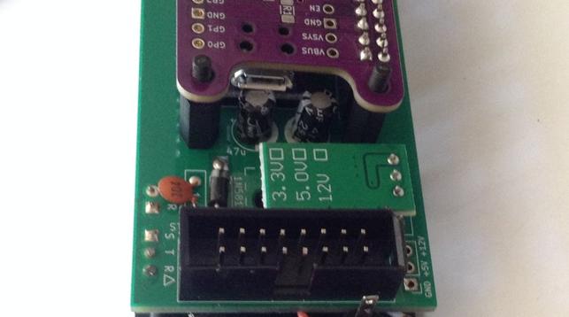
The nice thing about this PCB is that I can map everything nicely over to the pinouts used with my MiniDexed EuroRack PCB meaning that once the Pico has the custom firmware installed, it will just plug in and work and no hardware changes or patching is required at all!

I was slightly concerned that the USB port of the Pico might clash with the two installed electrolytic capacitors on the MiniDexed PCB, but in my case I can just about get away with it!

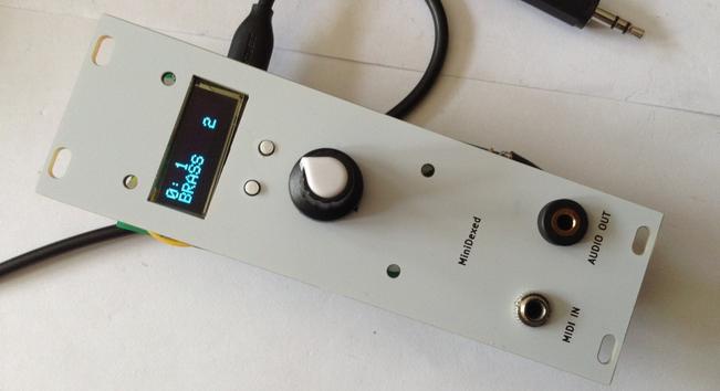
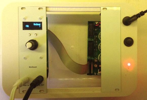
Here is the final assembled unit.

Closing Thoughts

I finally have my Eurorack picoDexed which is pretty neat. Big thanks to bablokb for putting that PCB up online. That saved me a job. And it was particularly nice that things like assuming consecutive pins for the I2S mapping was included as that made using the PIO I2S code a lot easier.

I’d like to see what the power usage is like now as I’m really after a lower power Dexed engine compared to the full Zero version.

Naturally at some point I might still make my own picoDexed Eurorack PCB, but this is a pretty good solution as far as I’m concerned, so that wouldn’t really add much for me now.

Kevin

#midi #minidexed #pcb #picodexed #raspberryPiPico

Simple DIY Electronic Music Projectsdiyelectromusic.com@diyelectromusic.com
2025-04-12

picoDexed + StackyPi + MiniDexed EuroRack

Now that I have a picoDexed with a display an encoder it is very tempting to create a version of my MiniDexed EuroRack PCB for it.

But as a short diversion, there is another possibility – can I use a RP2040 that is already in a Pi Zero form factor with my existing MiniDexed EuroRack PCB Design?

Spoilers: The answer, it turns out, is no. Something is not quite letting this work for me – it’s close, but I’m just not there yet. Here is another attempt where it works: picoDexed + MiniDexed EuroRack.

Warning! I strongly recommend using old or second hand equipment for your experiments.  I am not responsible for any damage to expensive instruments!

If you are new to microcontrollers and single board computers, see the Getting Started pages.

Pi Zero RP2040s

I’m aware of a couple of products that were available to put a RP2040 into a Raspberry Pi Zero form factor:

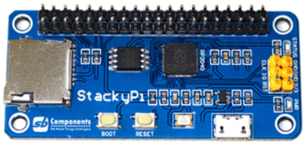
The first two were available on Tindie and other places, and as far as I can see, both appear to use the same mapping of RP2040 GPIO to RPi 40-pin header. The Red Robot board doesn’t seem to be available anymore, and whilst there are a few Stacky-Pis on Tindie, in most places it seems to be discontinued.

I don’t know anything about the Waveshare or Pico to Pi, but might grab myself one of each.

I’ll give the open source design a try (and possibly save me designing my own…).

As can be seen above, the Red Robots board is designed to take an actual Pico, whereas the Stacky-Pi is its own board with an on-board RP2040.

Mapping over to MiniDexed/RPi Zero

The following table lists the RPi GPIO connections I used in my MiniDexed board and how they map onto the RP2040 using the above boards.

RP2040UseRPiRpiUseRP20403V35VGP20LCD SDAGP2 SDA5VGP21LCD SCLGP3 SCLGNDGP4GP14 TXDGP0GNDGP15 RXDMIDI INGP1GP17GP18I2S BCLKGP28GP27GNDGP22GP233V3GP24GP3RE BGP10 MOSIGNDGP4RE AGP9 MISOGP25GP2RE SWGP11 SCLKGP8GNDGP7ID_SDID_SCGP10SW BACKGP5GNDGP11SW HOMEGP6GP12GP12GP13GNDGP13I2S LCLKGP19GP16GP26GP20GNDGP21I2S DATAGP15

The two key problem areas will be the I2S interface and encoder, which both require consecutive GPIO pins for the PIO code to do its magic.

The encoder should be fine – pins RE A and RE B map onto the Pico’s GP3 and 4.

The I2S interface is going to be tricky, as with a BCLK on GP28, it will be expecting LCLK on GP29 rather than the GP13 it is currently routed to on the board. Quite apart from the fact that GP29 isn’t even broken out on a Pico.

The obvious thing to explore is if the BCLK connection can be routed through to GP13 on the RPi header, or GP12 for the RP2040. That would be handy if so.

Connecting into GP13 should be possible as this pin is currently unconnected on the MiniDexed PCB. It will involve cutting a track however for GP18. The existing track and its new destination is highlighted below in blue.

Changing I2C Bus and UARTs

There is one other complication however. The picoDexed configuration has the ssd1306 connected to GP2 and GP3 which are multiplexed onto the I2C bus 1.

The adaptor configuration maps SDA/SCL onto GP20/21 which are multiplexed onto I2C bus 0. I updated the code to support changing I2C bus in addition to changing IO pins. Arguably, I should probably have supported this in the first place anyway…

A similar issue exists for the UART, but unfortunately that isn’t quite so easy to change.

I can take a similar approach to the above for the Serial MIDI link – allowing it to use either UART0 or UART1.

But that has to be matched with a change in the debug serial port too. But unfortunately, as far as I can see, that has to be configured in the master CMakeLists.txt file (as I talked about in Part 3).

New picoDexed GPIO Configuration

Given the above, the following new GPIO pins should be defined in config.h:

#define PWM_PIN         10

#define I2S_DATA_PIN 15
#define I2S_BCLK_PIN 12
#define I2S_LRCLK_PIN 13 // Implied by BCLK=12

#define MIDI_UART 0
#define MIDI_TX_PIN 0 // Not used
#define MIDI_RX_PIN 1

#define DEBUG_UART_TX_PIN 8
#define DEBUG_UART_RX_PIN 9

#define DISPLAY_I2C_BUS 0
#define DISPLAY_I2C_SDA 20
#define DISPLAY_I2C_SCL 21
#define DISPLAY_I2C_ADDR 0x3C
#define DISPLAY_W 128
#define DISPLAY_H 32

#define ENCODER_A_PIN 3
#define ENCODER_B_PIN 4 // Not used
#define ENCODER_SW_PIN 2 // Not used

In addition to this, to keep using the debug output requires the following lines adding to ‘target_compile_definitions’ in CMakeLists.txt.

    PICO_DEFAULT_UART=1
PICO_DEFAULT_UART_TX_PIN=8
PICO_DEFAULT_UART_RX_PIN=9

Bringing it all together…

I decided to hack on my (already pretty hacked) prototype MiniDexed EuroRack board and cut and patch the trace to the DAC as described above.

The complication being the GPIO header pin I need to get to is under the OLED display, but I could just about do it – see below.

It doesn’t work. Unfortunately.

First of, I have to say, I’ve not found the Stacky-Pi particularly reliable. It took me ages to get it to successfully boot up into accepting a uf2 file, and once installed, I was struggling to get it to reliably boot and run.

Weirdly it seems to work best when I have a finger on the flash chip which seems to imply some board layout/grounding/stability issues to me…

From what I can see, the display, MIDI, serial debug and encoder are working fine though once it does get up and running.

But I just can’t get any reliable sound out of the thing at all. I managed sound once, but that was it. It is all quiet unreliable for me – far too unreliable to be useful.

Shame, as it actually looks really cool!

Closing Thoughts

It has been a frustrating afternoon. I’m having to leave this one here for now as there are just too many unknowns at the moment to really get to the bottom of what is going on.

I thought the Stacky-Pi would be a quick and easy fix, but haven’t ever used them before, and the fact that they are discontinued and there is very little information that I can find online about them makes me think perhaps they aren’t worth persevering with.

So I have a number of options now:

  • Try a Waveshare RP2040 PiZero. As there are a lot more peripherals, I’m not sure how much what I’m doing will translate across, to be honest, it cost wise, it’s essentially the same as a Zero itself, which I know “just works”.
  • Do I design my own Pico to RPI GPIO converter board to let me use that with my existing MiniDexed EuroRack design? Tempting and probably not that hard.
  • Do I attempt to do something with the Pico version of my EuroRack 6HP MCU Experimenter Module? Sounds initially easy but I suspect forcing a MiniDexed into this module eventually will hit other at the moment unforeseen issues.
  • Or do I just go for it and put together a special picoDexed EuroRack module itself.

I might have one more go with the Stacky-Pi. I haven’t quite given up. I’ll have to do some research – maybe sprinkling a few capacitors around the board or some updated GND connections might help. Answers on a postcard (or in the comments) if you have any ideas.

I’ll get a Waveshare RP2040 PiZero on order, as I’ve had quite a bit of success with their own “Zero” miniature boards so far, and now I’d like it know if it would work 🙂

To be continued…

Kevin

#define #midi #minidexed #picodexed #raspberryPiPico #StackyPi

Simple DIY Electronic Music Projectsdiyelectromusic.com@diyelectromusic.com
2025-04-07

MT32-Pi on my EuroRack MiniDexed PCB

This is great. I was asked by Michel (mragutlich) if I knew how to build MT32-Pi to configure it for my MiniDexed EuroRack PCB but I don’t and there isn’t a lot of information apparently on how to build it from source.

So I offered my Rebuilding my Ability to Build MiniDexed post which talks about getting to the point of being able to build MiniDexed and as both synths run on circle, figured that would be a pretty good starting point.

And then Michel came back to me with a complete set of instructions for Ubuntu and I’ve just run through them – and they work great.

So massive thanks to Michel, this is how you could get MT32-Pi running on my MiniDexed EuroRack PCB.

https://makertube.net/w/2xzd8b4RPDPX1YJL3CpA57

Warning! I strongly recommend using old or second hand equipment for your experiments.  I am not responsible for any damage to expensive instruments!

Previous posts on MT32-Pi:

If you are new to microcontrollers and single board computers, see the Getting Started pages.

Parts list

  • Raspberry Pi Zero 2.
  • Micro SD card.
  • MiniDexed EuroRack PCB and panel.
  • Power, leads, additional connectors and so on.

Building MT32-Pi on Ubuntu

Here are Michel’s instructions that worked for me.

Setup a Ubuntu 20.4 LTS system.

sudo apt-get update
sudo apt-get upgrade
sudo apt-get install build-essential
sudo apt-get install gcc-arm-none-eabi
sudo apt-get install git
sudo apt-get install curl
sudo apt-get install dialog
sudo apt-get install cmake
sudo apt-get install pkg-config
sudo apt-get install glib-2.0 Now clone the mt32-pi github repo

git clone –recursive https://github.com/dwhinham/mt32-pi.git

cd mt32-pi

nano src/control/simpleencoder.cpp In nano change the following lines

constexpr u8 GPIOPinButton1 = 5;
constexpr u8 GPIOPinButton2 = 6;

constexpr u8 GPIOPinEncoderButton = 11;
constexpr u8 GPIOPinEncoderCLK = 10;
constexpr u8 GPIOPinEncoderDAT = 9;

ctrl-X and say ‘Y’

make all

If everything goes well you will have a kernel8.img file in your directory.

Now hook up a microSD cardreader to your Linux environment and insert a blank microSD card

Goto the ~/scripts dir and start mt32pi_installer.sh , this will install all the needed bare metal files

sudo ./mt32pi_installer.sh

When ready copy the kernel8.img file to the SD card

Change in the mt32-pi.cfg file the line ‘encoder_reversed = off’ to 'on', now the volume knob will increase when turned clockwise

Copy the MT32 roms to to the rom dir

Copy some Sf2 soundfont files tot the soundfont dir

Thats it…unmount the sd card , put it in your Zero 2 W…and boot it.. the MT32pi logo should appear on the oled screen and the buttons and rotary encoder should work properly

The first button switches between m32 and soundfont mode.

The second button will switch to the next rom or soundfont file

The rotary encoder will change the master volume.

The encoder switch only displays a message that the button is pressed

There were a couple of tweaks I needed. First of, the mt32_inistaller.sh script has to be run as root. This will go through and ask you to choose the SD card to format and install and so on.

At some point you will need some MT32 ROMs. There are details of how to do that on the original MT32-Pi project here: https://github.com/dwhinham/mt32-pi?tab=readme-ov-file#-quick-start-guide

In addition to the aforementioned “encoder_reversed” setting in the mt32-pi.cfg file there are a couple of other options I find used (many of these were already set up by the installer):

[system]
default_synth = mt32 or soundfount


output_device = i2s

[control]
scheme = simple_encoder
encoder_reversed = on
mister = off

[mt32emu]
midi_channels = alternate

[lcd]
type = ssd1306_i2c
width = 128
height = 32
i2c_lcd_address = 3c

I think those were the major changes.

I installed a single “new” ROM and a PCM ROM. The default soundfont is already installed. And that was essentially that.

The first time I tried it, I’d forgotten to copy over the kernel8.img file, so that took a moment to figure out! But apart from that it was all pretty straight forward for me. Many of the packages to install at the start were already there and up to date, so that didn’t take too long and the build itself was again fairly straight forward.

Closing Thoughts

A big thanks to Michel for asking the question, then figuring out the answer, and most importantly sending me the instructions and permission to post them here.

This is a great additional option for my PCB 🙂

The video shows the MT32-Pi in Soundfont mode playing a MIDI file of Khachaturian’s Masquerade Waltz.

It is great to have a full General MIDI Soundfont device in EuroRack format.

Kevin

#EuroRack #generalMidi #midi #minidexed #mt32Pi #soundfont

diyelectromusicdiyelectromusic
2025-03-21

Finally finished the build guide and design for my MiniDexed EuroRack module.

Definitely still a prototype and definitely still not for use in anything but a sacrificial system.

Plenty I could be doing to make it better, but it is probably at the "good enough to lose interest" stage for me now :)

diyelectromusic.com/2025/02/22

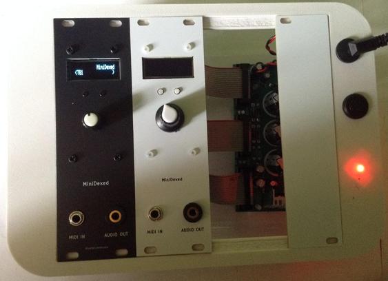
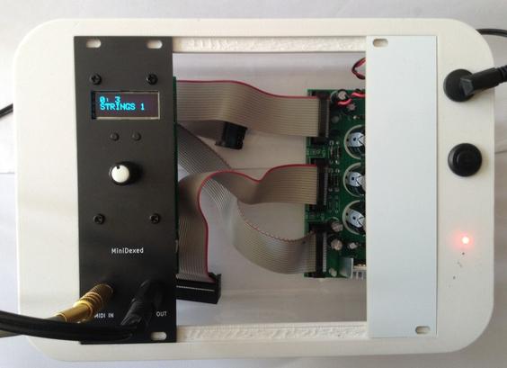
Photo of two 8HP DIY EuroRack modules, both essentially the same design, but one black, one white.  Both with a small OLED display at the top, encoder in the middle, and two TRS sockets at the bottom.  The black one on the left is powered up showing the "MiniDexed - TG1" display.  Both modules are in my cake-tub-EuroRack box for testing.
Simple DIY Electronic Music Projectsdiyelectromusic.com@diyelectromusic.com
2025-03-21

MiniDexed EuroRack PCB Build Guide

Here are the build notes for my MiniDexed EuroRack PCB Design.

This is a DIY module only for use in my own DIY system.

Do NOT use this alongside expensive modules in an expensive rack. It is highly likely to cause problems with your power supply and could even damage your other modules.

Warning! I strongly recommend using old or second hand equipment for your experiments.  I am not responsible for any damage to expensive instruments! 

If you are new to single board computers, see the Getting Started pages.

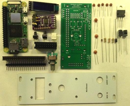
Bill of Materials

  • MiniDexed EuroRack PCB (GitHub link below)
  • Front panel
  • Raspberry Pi Zero (1 or 2)
  • GY-PCM5102 module
  • 128×32 SSD1306 OLED display module (pins order: GND-VCC-SCL-SDA)
  • 1x L7805 regulator
  • 1x H11L1 optoisolator
  • 1x 1N5817 Schottky diode
  • 1x 1N4148 or 1N914 signal diode
  • 1×220Ω, 1×470Ω resistors
  • 5x 10nF ceramic capactiors
  • 3x 100nF ceramic capacitors
  • 2x 47uF electrolytic capacitors (low profile if possible – see text)
  • 1x switched rotary encoder with a threaded shroud and nut
  • 2x tall tactile buttons – 6x6mm base, at least 12mm height (it needs to poke through the panel!)
  • 16-way shrouded EuroRack style power header.
  • 40-way GPIO header (optional: extended – see discussion).
  • Pin-headers and connecting wires.

Also required: 3.5mm panel mount sockets for audio and MIDI – I use different types, but it will depend on the panel used (see panel discussion).

Build Steps

Taking a typical “low to high” soldering approach, this is the suggested order of assembly:

  • Resistors and diode on the top.
  • H11L1 (assuming soldered directly to the PCB).
  • Disc capacitors on the top.
  • Diode and disc capacitor on the bottom.
  • Electrolytic capacitors on the bottom.
  • GPIO and 16-way power socket on the bottom.
  • Buttons and encoder on the top.
  • GY-PCM5102 module (see photos for steps required prior to fixing).
  • SSD1306 (see photos for steps required prior to fixing).

Here are some build photos and more details of the steps involved.

Note: Most of these photos show the build for V0.1 of the PCB. There are some minor updates in V0.2 which will be noted where relevant.

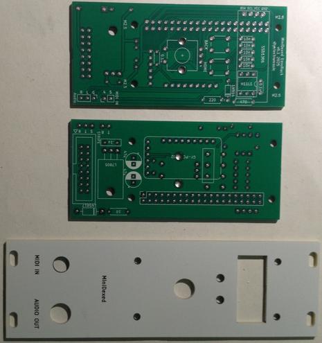
The power circuit on the underside of the board has two options for mounting the regulator. It can go either vertically or horizontally, but with the tab up. Both methods use the same solder holes. Which is chosen will largely depend on what heatsink options there are.

Note: the first version of the board only had a single option, with the tab down, making contact with the PCB. This didn’t really work from a cooling perspective, hence the change.

The following “in progress” photos still show the first version of the board with the regulator the other way around, an additional resistor, omitted from V2, and the diode in a different place.

Note that low-profile capacitors may be required as they will sit underneath the Raspberry Pi Zero. If the regulator is “standing up” then it should be possible to bend the capacitors over into the space reserved for the regulator.

The GPIO headers have to allow enough space for the Zero to be mounted and not interfere with the PCM5102. See discussion below.

The EuroRack headers need to be correctly oriented and shrouded headers are strongly recommended.

The SSD1306 requires additional spacers on the pins to raise it above the PCB for presentation closer to the front panel.

The PCM5102 must have its solder jumpers configured, if not set already, and requires both sets of pin headers adding.

In the photo below, the PCM5102 has zero-ohm, surface mount resistors as jumpers – but it is really hard to see! On first glance, it looks like there is no link configured at all, but they are connected as: 1L, 2L, 3H, 4L.

These modules have to be added after the other components, as they prevent access to the solder pads during assembly.

GPIO Header Options

One option is to use extended headers, which ought to allow room for the Zero and a heatsink (if required) on the main BCM chip. Note: A V2 Pi Zero could probably benefit from a heatsink I’d imagine if running fully processing all 8 tone generators.

Another option is to remove the on-board 3.5mm, SMT, audio jack on the PCM5102 as shown below, and use “normal” sized GPIO headers.

If non-extended GPIO header is used then, as already mentioned, low-profile electrolytic capacitors may be required as they are positioned underneath the Pi Zero too.

Power Options

As previously mentioned, there wasn’t really much choice when it came to mounting the power regulator for V1 of the board, but in V2 I’ve positioned it differently to allow it to be “tab up” or upright.

The upright positioning was hopefully placed so that a long, thin heatsink could be mounted alongside the Pi. This shows one of those heatsinks you can get for M2 SSD cards. I figure that drilling a hole in it would do the trick, but I’ve not actually done this myself (see below).

The solution I went with in the end was to actually replace the 7805 with a 7805-compatible DC-DC buck converter. These are available fairly cheaply online.

These work a lot more efficiently than a 7805, so especially when drawing 300mA or so from a Pi Zero 2 whilst dropping from 12V down to 5V, they still have no need of a heatsink.

The downside of using these (apparently) is that as a switching power unit, they can be pretty electrically noisy. But as I’m powering a microcontroller rather than a pure analog circuit in the first place, I decided it probably wasn’t going to be making things much worse. This is hardly a high quality, electrically clean build anyway!

Final Assembly

Required Components to use my panel:

  • MiniDexed EuroRack Panel (see Github link below).
  • Raspberry Pi Zero (1 or 2) with GPIO header pins.
  • MiniDexed EuroRack PCB as described above.
  • Panel mount 3.5mm TRS socket for MIDI. 6mm diameter hole assumed.
  • Panel mount 3.5mm TRS socket for audio. 8mm diameter hole assumed.
  • 2.5mm mounting posts, screws and nuts.

I’m using the same designs of TRS sockets for MIDI and audio that I use in all my modules. These need mounting on the panel. Soldering will come in a moment.

I found that with the GPIO header height I was using, alongside the final height of the SSD1306, height of the buttons, and the encoder’s shroud, that the following mountings were required:

  • 2x black nylon 2.5mm 6mm screws
  • 2x black 10mm 2.5mm spacers
  • 2x white 8mm 2.5mm spacers with screws
  • 2x white nylon 2.5mm 6mm screws

An alternative build had a slightly larger gap (due to using 12mm buttons) so required four sets of 10×2.5mm spacers.

Another quirk of my first build was that I only had 9mm high buttons which wasn’t quite enough to reach through the panel. Ideally a 11mm or larger button would be required.

But this allowed me to 3D print a white 2.8mm diameter, 3.0mm high, extension that I could glue on the top, meaning that the exposed part of the button was white, matching the panel.

My second build used a black panel and 12mm buttons, but as already mentioned this meant the panel had to use 10mm spacers instead of 8mm spacers. One issue with that is that there isn’t much of the encoder shaft exposed. I found some knobs that worked ok, but my preferred (cheap) knobs could not be fitted and still allow the encoder switch to function.

In summary, there is still a fair bit of trial and error with each build depending on the exact combinations of screen height, encoder shaft length, button length and so on.

Once the PCB and panel is fixed together then the two 3.5mm sockets can be soldered to the PCB (or connected using headers if that was the preferred option).

Recall that MIDI IN does not required a GND connection. Also double check which solder tabs correspond to the TIP and which to the RING, which should match the “T” and “R” labels on the PCB (“S” is for shield, i.e. GND).

Testing

I recommend performing the general tests described here: PCBs.

Then, prior to plugging in the RPi Zero, do the following:

  • Verify that the 12V and GND connections of the EuroRack connector have no shorts.
  • Power up the board (no Pi) and verify that there is a 5V signal present and going to the PCM5102 and SSD1306. The PCM5102 should have its red power LED on.

Only then power off, plug in the RPi Zero with an SD card containing MiniDexed (configuration below) and verify that the display, encoder, buttons, MIDI IN, and audio out are all working.

MiniDexed Configuration

The following are the key MiniDexed.ini configuration options required:

SoundDevice=i2s

SSD1306LCDI2CAddress=0x3C
SSD1306LCDWidth=128
SSD1306LCDHeight=32
LCDColumns=20
LCDRows=2

ButtonPinBack=5
ButtonActionBack=click
ButtonPinSelect=11
ButtonActionSelect=click
ButtonPinHome=6
ButtonActionHome=click
ButtonPinShortcut=11

EncoderEnabled=1
EncoderPinClock=10
EncoderPinData=9

PCB Errata

As already noted, there were a number of issues with the first version of the PCB, but these should have been addressed in the published version.

As the time of writing, there are no further known issues with V0.2 of the PCB.

Enhancements:

  • I feel like the power situation ought to be better. One option could be to break out a USB connection to the Zero directly allowing the use of a standard “wall wart” type supply.
  • Another option might be to make use of the solder pads on the rear of a Zero (like the Zero STEM does).
  • It might also be useful to provide a configurable (e.g. solder bridge) link to enable the EuroRack +5V supply as an option.
  • There are already options to use internal (within a rack) links for MIDI and audio if required using the pin headers on the PCB, but it might be nice to allow a choice between panel or rear connectors.

Find it on GitHub here.

Closing Thoughts

I’m still not fully happy with the longer-term implications of how I’m powering these boards, but I’ll see how things go. Those DC-DC converters seem like a feasible option so I’ll see how they perform.

The panel height issue could be better too – it would be nice to have a recommended set of components and a known useful size of spacers, but there is still a fair bit of trial an error at the moment with each build.

Also, sometimes the display height isn’t perfect, as shown below. I might 3D print a display bezel or surround to help.

The end results looks pretty good though, so for this stage in my thinking about these, I’m pretty pleased with how this has ended up.

But one last time, just to make my position totally clear: this is a DIY system and should only be used with other DIY modules you wouldn’t mind too much losing.

It is NOT for use alongside other commercial (expensive) or treasured modules. There are commercial versions of MiniDexed apparently for that, that I have no experience of.

Kevin

#EuroRack #midi #minidexed #pcb #RaspberryPiZero
diyelectromusicdiyelectromusic
2025-03-02

Couple of interesting, cheap modules that seem to work pretty well with MiniDexed. Details here:

diyelectromusic.com/2025/03/02

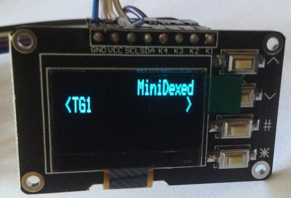
Photo of an approx 40x25mm module with a blue 128x64 OLED display and four buttons down the right hand side.
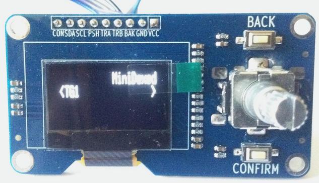
Display shows "MiniDexed" and "TG1".Photo of an approx 65x53mm module with a white OLED display and on the right hand side a rotary encoder and two buttons.
Display shows "MiniDexed" and "TG1".
Simple DIY Electronic Music Projectsdiyelectromusic.com@diyelectromusic.com
2025-02-22

MiniDexed EuroRack PCB Design

I’ve seen a number of EuroRack format MiniDexed versions now, from 3D printed panels and designs, right through to commercial modules.

It’s something I’ve been meaning to do for a while, so this is my first attempt at a take on a 8HP EuroRack format MiniDexed using a Raspberry Pi Zero 2 W.

This is a DIY module only for use in my own DIY system.

Do NOT use this alongside expensive modules in an expensive rack. It is highly likely to cause problems with your power supply and could even damage your other modules.

Warning! I strongly recommend using old or second hand equipment for your experiments.  I am not responsible for any damage to expensive instruments!

If you are new to single board computers, see the Getting Started pages.

The Circuit

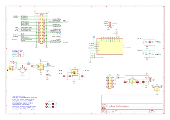
In terms of the circuit, this is essentially my MiniDexed Raspberry Pi IO Board in the SSD1306 format with the EuroRack power supply from my EuroRack 6HP MCU Experimenter Module.

I did toy with the idea of not bothering with a 5V regulator and powering the Pi from the EuroRack 5V line, but I didn’t for a couple of reasons:

  • The Pi has no particular protection on its 5V circuit as I understand things, so directly connecting that to the outside world seems like not a good thing to do.
  • Using the 12V line and a built-in regulator makes the module more generic in terms of what power it will accept within a EuroRack specified rack system.
  • It is easier to protect the 12V/GND setup if a cable is plugged in the wrong way round, than it is for the 5V power lines.
  • A fairly inert Pi Zero 2 apparently draws something like 350mA, so it will be quite a drain on a 5V rail, which tend to be spec’d a fair bit lower than the 12V rails. A Pi Zero V1 would have a typical current of around 150mA peaking at ~350mA so that is always an option.

For these reasons I included a 12V to 5V conversion via an L7805 regulator to power the Pi. It does get a bit hot though with a Zero 2, so that has to be taken into account – something I hadn’t done in my first version of this board!

Aside: there are two L7805 regulators shown on the schematic as I’m going to include two footprint options on the PCB itself.

One other thing I’ve left out is the 10Ω resistor. I was largely following comments online when I included it before, but from reading some more (some good discussions here, here and here), I can see that they tend to be included instead of a fuse. But if the Pi is drawing a few 100mA and this is in the 12V input line, then that will be quite a bit of power as I understand things dissipated through that resistor already, so I’ve left it out.

The rest of the circuit is designed around a Raspberry Pi Zero with an I2S audio output via a GY-PCM5102 module, but I’m planning on using headers to link to MIDI IN and audio out on a panel.

I’m not supporting USB MIDI, just serial MIDI. I’m also only supporting MIDI IN.

There are a few components left on the schematic that I’ll be omitting when it comes to putting the PCB together, but I’ve left them there as reminders for the future.

PCB Design

The general idea is to have most of the circuitry on a single PCB that will fit within a 8HP EuroRack module. This means a 40mm (or less) wide PCB and ideally 100mm (or less) long to keep within cheap PCB limits. This works well with EuroRack, leaving 14mm top and bottom for mountings.

I’ve therefore opted for a PCB-mounted encoder, buttons and display and headers linking off to an off-board (still on the panel) MIDI IN socket and Audio OUT. The final PCB is 40x88mm.

Power will come from a EuroRack compatible 16-way connection which will be on the rear of the board. A Pi Zero will also be mounted on the rear of the board.

For expediency I’ve also mounted the GY-PCM5102 on the rear of the board. I’d have quite liked to have made the 3.5mm TRS socket accessible, but I just couldn’t make it all fit. For basic use I was planning on using the L/R/AGND connections anyway to a 3.5mm TRS socket taken to the front panel.

Ideally I’d have used 3.5mm stereo Thonkiconn style connections, but in the end I went for panel-mounted TRS sockets and header connectors instead.

The spacing of the controls isn’t optimum but I was having to compromise with mounting of components and mounting of the encoder and buttons. I think it will be ok, but I’ll have to see when I get it back.

As previously mentioned, not everything on the schematic has been realised on the PCB. I’m going for off-board audio and MIDI jacks, and I’m not bothering with headers for the buttons.

Also, as previously mentioned, I’ve included two footprint options for the L7805 – one vertical and one (tab up) horizontal. The idea is to provide options when it comes to adding a heatsink.

Front Panel

I’ve design a panel to match. This is just using KiCAD to create a PCB panel, as I’ve done before.

I’ve had to take a bit of a punt with the dimensions of the display. I won’t really know how it will mount until I get all the parts back and try them out.

I’ve taken the mounting holes forward from the Pi through to the panel. Without those, only the encoder would have been keeping the PCB and panel together.

Somewhat annoyingly, I noticed as I was writing this blog post, that I had a stray ref** silkscreen element for the audio jack. When I received the boards back, I had to gently scrape that off with a razor blade.

When I sent off the updated PCB I took the opportunity to also order some more panels with that fixed, but it means I’ll have a choice of either white or black panels when I’m done.

Closing Thoughts

This is something I’ve been wanting to do for some time, so it’s nice to have finally had a look. I kept with the “white look” I’ve been using for my EuroRack experiments so far, but will have a black option too.

The first version had a few issues. First, annoyingly, I managed to get the SSD1306 footprint the wrong way round, so I had a few bodge wires to fix that. And then there were issues with the heat dissipation from the regulator, so all in all, I’ve moved onto a v0.2 of the PCB (unusually for me – I usually just make do :)).

I’m still not convinced about the power situation. Driving a Pi via a L7805 does seem to waste quite a lot of energy, so I need to watch out for the heatsink situation as the build comes together. It might be that directly powering using a USB supply is better, so I might revisit this in the future.

That stray ref is annoying, but that is what you get when you change the size of a hole at the last minute and don’t notice a reference changing layers. So that is just bad luck I guess (unless I really should up my verification process before hitting “send”!).

But then the whole panel was a bit of an experiment as the screen, particularly, was hard to judge up-front without any kind of spatial model, but there seem to be enough options to largely make it work.

So still very much a work in progress, but I think there is a lot of promise, and having a couple of these in a rack does look really neat.

But the general advice still stands – this is a DIY system and should only be used with other DIY modules. If you want a MiniDexed for use in your treasured EuroRack setup alongside your expensive modules, then there are commercial options available, although naturally I have no experience of them myself.

Kevin

#EuroRack #midi #minidexed #pcb #RaspberryPiZero
diyelectromusicdiyelectromusic
2024-10-12

Turns out you can use the old Google/Raspberry Pi AIY Voice HAT as the audio output for a MiniDexed.

diyelectromusic.com/2024/10/12

makertube.net/w/hu8qmtHg4xQY1k

Simple DIY Electronic Music Projectsdiyelectromusic.com@diyelectromusic.com
2024-10-12

Someone asked on the MiniDexed forums if the Google/Raspberry Pi AIY Voice HAT could be used with MiniDexed. This reminded me that I had V1 of the kit tucked away in a corner somewhere, so decided to finally take a look at it!

Warning! I strongly recommend using old or second hand equipment for your experiments.  I am not responsible for any damage to expensive instruments!

If you are new to microcontrollers and single board computers, see the Getting Started pages.

Parts list

  • Raspberry Pi 3
  • AIY VoiceKit
  • USB MIDI Controller

AIY Voice HAT

The core project information can be found here:

And here are some additional sources of information:

The Google-designed AIY Voice HAT is an add-on board designed for use with a Raspberry Pi 3 to provide audio input and output, with breakout connections for I2S, SPI, servos and motor drivers. Audio input is provided via two MEMS microphones that stream I2S directly into the Pi and audio output is provided by a MAX98357A – a “Tiny, Low-Cost, PCM Class D Amplifier with Class AB Performance” according to the datasheet.

This is the same device used on the “Adafruit I2S 3W Class D Amplifier Breakout – MAX98357A” and in fact, if you look at the schematic for the voice HAT there is an interesting section that seems to imply that one of the Adafruit modules can be added to provide a second channel output for full stereo operation.

And it can be seen that there is a row of 7 unmarked pin header holes that when paired with a couple of additional holes the other side of the onboard MAX98357A, looks suspiciously like the pin footprint of the Adafruit board.

And sure enough, in the guide it does suggest adding that module to give a right channel output (see more here).

Audio on the AIY Voice HAT

In terms of GPIO interface, the full details can be found at pinout.xyz here and in the AIY Voice datasheet, but the relevant ones for audio output are as follows:

Physical PinGPIOFunction25V Power6GND1218I2S Clock3519I2S WS3616Amp Shutdown3820I2S Data IN4021I2S Data OUT

These are standard power and I2S (PCM) audio connections, apart from GPIO16 “Amp Shutdown”. This is connected to “SD_Mode” of the MAX98357A (see above schematic section). The datasheet tells us that driving this LOW will put the amp into shutdown. But it also says it is responsible for selecting the mode of the amplifier, depending on the resistor used to drive SD_Mode HIGH. Example resistor values are provided for 1.8V and 3.3V operation:

There is a solder jumper on the board that changes the resistances to enable stereo mode – i.e. L channel goes to the onboard MAX98357A and R channel goes to the Adafruit add-on module.

For operation with MiniDexed, this pin just has to be held HIGH to 3.3V.

Also, of course, MiniDexed has no audio input, so GPIO20 (pin 38) just has to remain unused.

AIY Voice HAT Other Pins

Key additional functions for a MiniDexed would typically be:

  • Serial MIDI interface via the UART (RX/TX).
  • Display either via direct GPIO or over I2C.
  • Button inputs.
  • Rotary encoder.

In terms of the AIY Voice HAT, there are breakouts for I2C, SPI and then bespoke output driver connections for servos or motors. The button header includes outputs for a LED and an input for a button switch (which is also duplicated by the on-board button).

This means the following GPIO pins are easily available for MiniDexed purposes:

GPIOTypical AIY UsePossible MiniDexed Use2I2C headerI2C SDA for display3I2C headerI2C SCK for display7SPI headerGeneral IO8SPI headerGeneral IO9SPI headerGeneral IO10SPI headerGeneral IO14TXD headerTX for MIDI15RXD headerRX for MIDI22SPI headerGeneral IO23ButtonButton Input

All other GPIO pins include electronic circuitry as part of the AIY HAT which means it would be somewhat problematic to use for other purposes.

Use with MiniDexed

So for basic audio output it is possible to use the AIY Voice HAT with MiniDexed provided that GPIO 16 (Amp Shutdown) can be set HIGH.

Thankfully the Raspberry Pi has the config.txt file which is read and processed on startup before any operating system runs and this has the ability to preset GPIO pins to a defined state.

To use the AIY Voice HAT with MiniDexed therefore requires the following configuration.

In MiniDexed.ini, configure sound output to be I2S:

SoundDevice=i2s

In config.txt, preset GPIO 16 to be HIGH:

gpio=16=op,dh

Then be sure to check that any other GPIO uses in minidexed.ini do not conflict with any of the GPIO pins used by the AIY Voice HAT.

Then it is just a case of connect up the speaker, plug in a USB MIDI controller, and it just works.

https://makertube.net/w/hu8qmtHg4xQY1khWfGvFdE

Closing Thoughts

Apparently these HATs can be bought quite cheaply these days, and I suppose if you have one lying around already (that you got a number of years ago off a magazine!) then it is an easy source of an I2S DAC.

But really, it isn’t easy to build out the other MiniDexed interface components to make a fully functional system, so I’d probably say save you AIY HAT for some neat robotics applications and just get a GY-PCM5102 module.

But if you want to get on an use the AIY Voice HAT as your sound output for a MiniDexed, then yes. It works. And so would the Adafruit MAX98357A breakout.

Kevin

https://diyelectromusic.com/2024/10/12/aiy-voice-hat-and-minidexed/

#aiyVoiceHat #MAX98357A #minidexed

2024-10-12
diyelectromusicdiyelectromusic
2024-06-10

@themagpi I've built up a PCB to support four GY-PCM5102 DACs with a Raspberry Pi 5 and MiniDexed to give 8-channel audio output.

Includes: 4xDACs, SSD1306 display, encoder, buttons, MIDI IN/OUT.

Full details here: diyelectromusic.com/2024/06/09

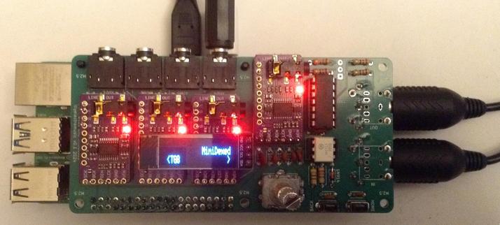
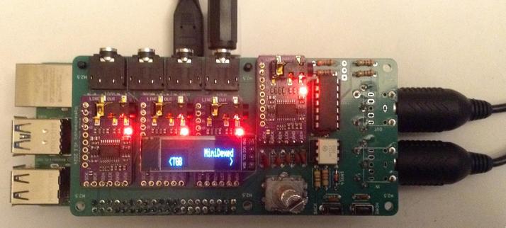
Photo of a custom PCB on a Raspberry Pi 5.  The PCB includes four GY-PCM5102 modules, four TRS outputs, MIDI connectors, and a OLED display showing"MiniDexed" and "TG8"
diyelectromusicdiyelectromusic
2024-06-09

I've built up a PCB to support four GY-PCM5102 DACs with a Raspberry Pi 5 and MiniDexed to give 8-channel audio output.

Includes: 4xDACs, SSD1306 display, encoder, buttons, MIDI IN/OUT.

Full details here: diyelectromusic.com/2024/06/09

Photo of a custom PCB on a Raspberry Pi 5.  The PCB includes four GY-PCM5102 modules, four TRS outputs, MIDI connectors, and a OLED display showing "MiniDexed" and "TG8".
diyelectromusicdiyelectromusic
2024-05-30

@Maker_of_Things@strangeobject.space @makershour A1 Hello Kevin here. Feels like ages since I've managed a !

I've been flitting about with different projects really, but the main thing has been my pseudo-educational synth thing I've been working on - that has several posts about it now.

Also, I keep tinkering with too, which incidentally got a mention in @themagpi this month.

makertube.net/w/ke5t911VHa5yP7

diyelectromusicdiyelectromusic
2024-05-28

And hopefully I now have a test build of that supports this too.

github.com/probonopd/MiniDexed

diyelectromusicdiyelectromusic
2024-05-05

I appear to have MiniDexed (and circle) supporting ST7789 displays now, which means I can use a Pimoroni Pirate Audio with MiniDexed!

If you only need USB MIDI this is about as simple an option as it will be possible to have.

It would be a particularly neat, self-contained Pi Zero USB Gadget...

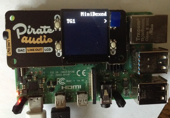
Photo of a Pimoroni Pirate Audio hat on a Raspberry Pi 4 with the display showing "MiniDexed" and "TG1".
diyelectromusicdiyelectromusic
2024-04-25

@Maker_of_Things@strangeobject.space @makershour A5 Well, since I somewhat serendipitously fell into working on I've done one - the Yamaha TX816 8-way DX7 synth (or as close as I needed to do it for me).

I'd really like to do something for the Casio CZ synths, but I've not found any code out there as a starting point yet and it is probably quite beyond me to do the maths from scratch.

diyelectromusic.wordpress.com/

diyelectromusicdiyelectromusic
2024-04-22

@themagpi We've merged in preliminary Raspberry Pi 5 support to MiniDexed thanks to Rene's excellent Circle bare metal OS now supporting it. It's still considered experimental and doesn't currently do anything a Pi 3 or 4 can't do, but it does appear to work.

The photo is me testing PWM audio output on my Pi 5.

github.com/probonopd/MiniDexed

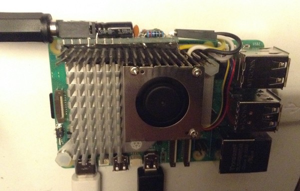
Photo of a Raspberry Pi 5 with the official cooler installed and a home made PWM output circuit hanging off a GPIO pin header socket.
diyelectromusicdiyelectromusic
2024-04-18

This is great new video about with a particular focus on the performance presets.

youtube.com/watch?v=uFpr1-5iYFI

diyelectromusicdiyelectromusic
2024-04-15

I've managed to get a build of MiniDexed working on a RPi 5 all thanks to Rene's excellent work on the circle bare metal environment for the Pi.

Early days, but the rate of development in circle is pretty astonishing!

github.com/probonopd/MiniDexed

2024-04-13

TIL: Es gibt einen quelloffenen #FM #Synthesizer, der sich eng am 80er-Klassiker #Yamaha #DX7 orientiert und bare-metal (ohne Betriebssysteme wie Linux direkt auf der Hardware) auf einem #RaspberryPi läuft.

github.com/probonopd/MiniDexed

#MiniDexed #Musik

Client Info

Server: https://mastodon.social
Version: 2025.04
Repository: https://github.com/cyevgeniy/lmst