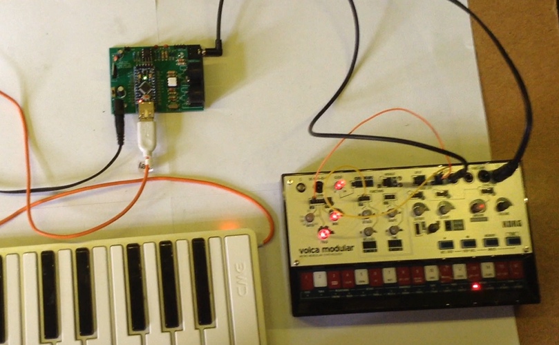
Another video. This time doing the USB to Serial MIDI and CV/GATE at the same time, so it can drive both a Korg Volca Modular and Korg Volca Keys...
#Volca
Arduino USB MIDI to Serial MIDI, CV and GATE
USB MIDI to Serial and CV/GATE
This project uses my Arduino Pro Mini MIDI USB CV PCB for a USB MIDI to Serial MIDI and CV/GATE device that has a CV/GATE that is compatible with my Korg Volca Modular.
It takes MIDI NoteOn/NoteOff and translates them into CV that can be used to set the pitch of a CV/GATE synth.
IMPORTANT: I strongly recommend that you do not connect this to your Volcas. I am not an electronics person but have accepted the risk of causing a possibly expensive problem. I will not be held responsible if you end up doing the same.
https://makertube.net/w/puRwMGeELa5zq3YhMrMC4h
https://makertube.net/w/cPjFeqigcrBHgMMPLjPNPb
Warning! I strongly recommend using old or second hand equipment for your experiments. I am not responsible for any damage to expensive instruments!
If you are new to Arduino, see the Getting Started pages.
The Circuit
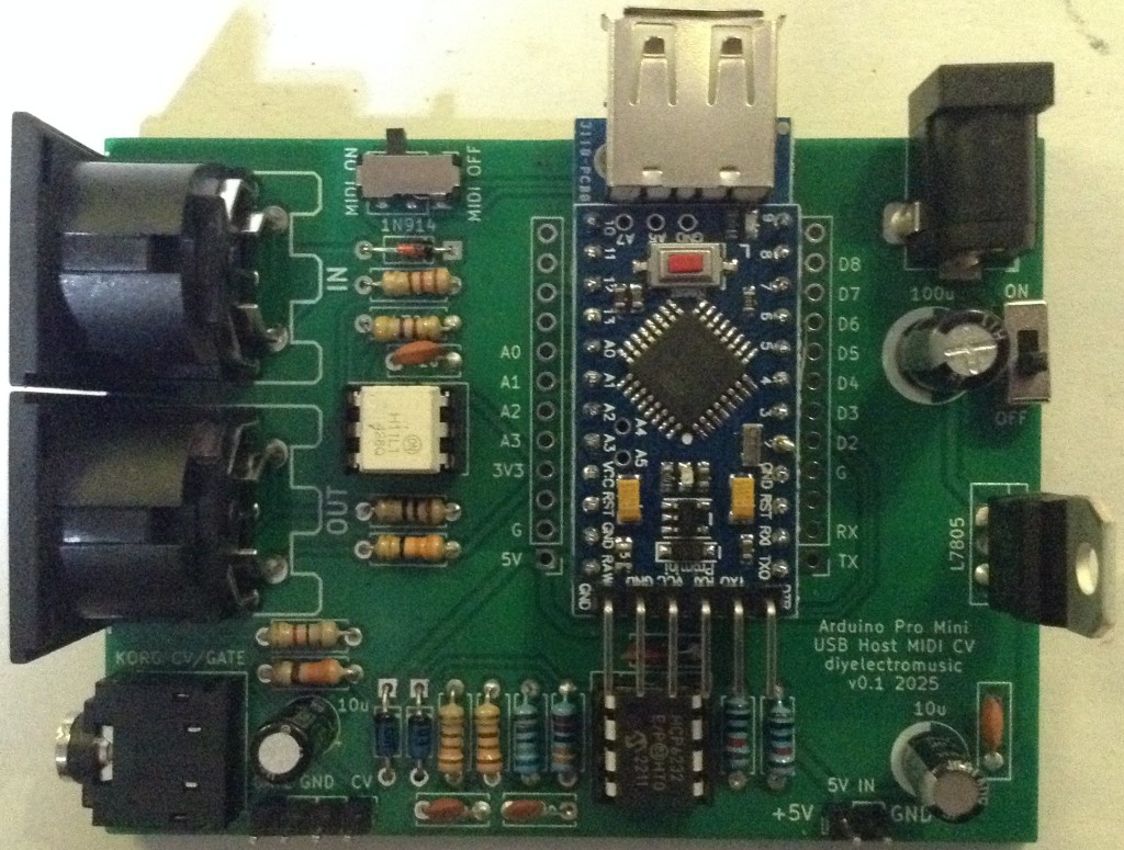
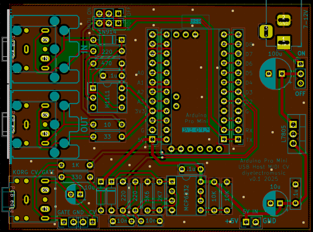
This is an application for my completed Arduino Pro Mini MIDI USB CV PCB.
The Code
The board was designed to require a PWM output on D3. With hindsight, D9 might have been more useful as D9 is a “Timer 1” timer on the ATMega328, but D3 is a “Timer 2” timer. The former are 16-bit timer/counters. The latter are only 8-bit.
No matter. I still have 255 levels of PWM to play with.
The initial PWM criteria I wanted were:
- No prescalar – run at full CPU speed. In the case of a 3V3 Pro Mini this is 8MHz.
- Use FastPWM mode – this will count up and then reset to zero.
- Use a TOP value of 255 – the maximum.
- Use the OC2B output, which is connected to D3. OC2A is not used.
- Use the mode where OC2B is cleared on compare match; set at 0 (BOTTOM).
- The PWM value is therefore written into OCR2B.
At some point the code will have to translate from MIDI note number over to a PWM value. My previous project mapped MIDI note C2 (36) onto 0V and went up from there for 5 octaves to C7 (96). This is a range of 60 steps, so actually, revisiting the PWM code, if we change the mode to use an alternative TOP Value of 239, that means each MIDI note corresponds to a specific step of 4. That would be pretty useful!
So the updated PWM criteria is now as follows:
- No prescalar – still run at full CPU speed. In the case of a 3V3 Pro Mini this is 8MHz.
- Use FastPWM mode – this will count up and then reset to zero.
- Use a TOP value of OCR2A, which will be set to 239.
- Use the OC2B output, which is connected to D3. OC2A is not used.
- Use the mode where OC2B is cleared on compare match; set at 0 (BOTTOM).
- The PWM value is therefore written into OCR2B.
The PWM operating frequency is given by a formula in the datasheet, but is basically the time it takes for the counter to count from 0 to 239 and reset, whilst running at 8MHZ. So the PWM frequency = 8000000 / 240 = 33.3kHz.
At such a frequency the (now updated) PWM filter components chosen give a pretty smooth output between 0V and 3.3V, which are them amplified using the OpAmp for a 0V to 5V range.
Note: No interrupts are required for the operating of PWM in this manner. We can just update the PWM value whenever is useful during the operation of the code.
The complete PWM code is thus as follows
void initPwm() {
  pinMode(3, OUTPUT);
  TCCR2A = _BV(COM2B1) | _BV(WGM21) | _BV(WGM20);
  TCCR2B = _BV(WGM22) | _BV(CS20);
  OCR2A = 239;
}

void setPwm (uint8_t pwmval) {
  OCR2B = pwmval;
}
The value used for PWM will only be active for 0-239. Any value of 240 or higher will just be considered “always on”.
This all means that converting from MIDI to PWM value is now pretty trivial:
#define MIDI_LOWEST_NOTE  36 // C2
#define MIDI_HIGHEST_NOTE 95 // C7
uint8_t midi2pwm (uint8_t note) {
  if (note < MIDI_LOWEST_NOTE) note = MIDI_LOWEST_NOTE;
  if (note > MIDI_HIGHEST_NOTE) note = MIDI_HIGHEST_NOTE;
  return (note - MIDI_LOWEST_NOTE) * 4;
}
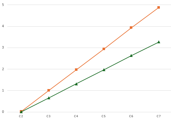
Logging the average voltage for each MIDI note (pre and post amplification) gives me the following:
C20.080.08C30.721.06C41.352.03C52.023.01C62.653.95C73.284.90Plotting these on a graph looks like this:
That is a pretty good linear response, but is slightly under in terms of the top-end output. At 1V/oct a semitone is around 83mV, so dropping 0.1V at the top ought to be dropping a semitone.
But jumping through the octaves it sounds all right to me. It’s definitely not dropping a semitone anyway, so I’m not sure what is going on. I might need to come back to this one!
The rest of the code is fairly straightforward MIDI reception and processing that I’ve done several times before now. There are a few design notes:
- Automatic MIDI THRU is turned off or both serial and USB MIDI.
- When a note that is not on the required channel or is out of the C2-C7 range is received, it is ignored.
- Anything received over USB is automatically sent to the serial OUT and anything received over serial is automatically sent to the USB OUT.
- NoteOff is only processed if received for the currently playing note.
- Consecutive NoteOn messages update the CV and replace the previously playing note.
- There is an option for a GATE type operation:
- GATE goes HIGH on NoteOn.
- GATE goes LOW on NoteOff.
- Or for a TRIGGER pulse type operation:
- GATE goes HIGH on NoteOn.
- GATE remains HIGH for a defined time (e.g. 10mS) then automatically goes off.
- On reception of NoteOff there are several possible options for what to do with the CV:
- Leave it and do nothing. This allows any envelopes to complete on removal of the GATE signal with no change of CV. But the CV will remain at the last level until a new note is received.
- Set it to the NoteOff pitch received. Although in reality this is probably going to be the same as “do nothing”.
- Set the CV to 0. This means there is no “dangling” CV voltage, but the synth will probably respond to the changing CV.
- I’ve left in a compile-time PWMTEST mode that just plays the different Cs for measuring voltages, and so on.
Closing Thoughts
This actually seems to work surprisingly well. I did wonder if the apparent inaccuracies of the output might cause an issue, but it doesn’t seem to.
The PWM filter issue was annoying, but on the one hand, it was a lot easier to build and debug with a PCB in hand; but of course on the other hand, if I’d done it first on solderless breadboard, the problem would have almost certainly be spotted and the design would probably have been right.
This has only looked at a pitch CV. It would be interesting at some point to do some kind of MIDI CC to CV control device.
Kevin
#arduinoProMini #cv #define #korg #midi #midi2cv #usbMidi #volca
Arduino Pro Mini MIDI USB CV PCB Build Guide
Here are the build notes for my Arduino Pro Mini MIDI USB CV PCB Design.
Warning! I strongly recommend using old or second hand equipment for your experiments. I am not responsible for any damage to expensive instruments!
If you are new to electronics and microcontrollers, see the Getting Started pages.
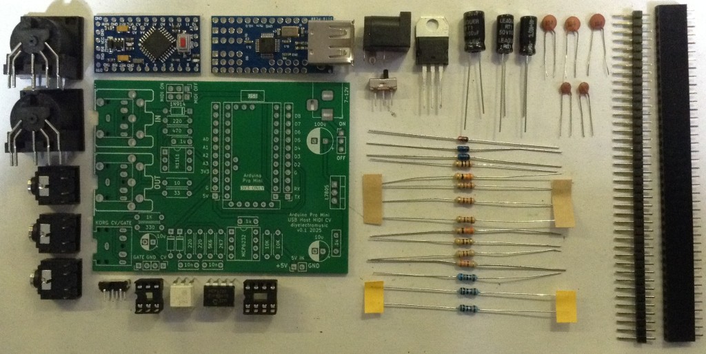
Bill of Materials
- Arduino Pro Mini USB MIDI Host CV PCB (GitHub link below)
- Arduino Pro Mini (3V3/8MHz version)
- Mini USB Host Shield 2.0
- 1x H11L1
- 1x MCP6232
- Diodes: 1x 1N4148 or 1N914 signal diode; 2x BAT43 Schottky
- Resistors: 10Ω, 33Ω, 1x 220Ω, 330Ω, 470Ω, 3x 1K, 2K7, 5K6, 2x 10K (*)
- Ceramic Capacitors: 4x 100nF (*)
- 1x 3.5mm stereo TRS
- Either 2x 3.5mm stereo TRS OR 2x 5-pin, 180 degree MIDI DIN sockets
- Pin headers
- Optional: 2x 12-way pin header sockets
- Optional: 1x 6-way DIP socket; 1x 8-way DIP socket
* The PCB shows the use of 2x 10nF and 2x 200Ω resistors for the PWM filter part, but 100nF and 1K work much better.
Optional: Power circuit
- 7805 regulator
- Electrolytic Capacitors: 1x 10uF, 1x100uF
- Ceramic Capacitors: 1x 100nF
- 1x SPST power switch 2.54mm pitch
Build Steps
Taking a typical “low to high” soldering approach, this is the suggested order of assembly:
- Diodes
- Resistors
- DIP sockets (if used) and TRS sockets (if used).
- Disc capacitors.
- Switches (if used).
- Jumper headers.
- Electrolytic capacitors (if used).
- DIN sockets (if used).
- 7805 (if used).
- Arduino + USB Host Shield (see notes below).
The Arduino Pro Mini and USB Host Shield need to be soldered together as a unit. If using header sockets, these will require longer header pins and will need soldering together as a single unit “off board”.
If not using sockets, normal pin-headers should suffice, in which case it is probably easier to solder the pin headers to the PCB and then add the USB Host shield, followed by the Pro Mini.
The USB Host shield requires a track cutting and a connection made from the Arduino’s VIN to the shields VBUS pad. See photos and discussion in the text.
Note: the PCB incorporates a capacitor on the CV PWM output to the TRS socket. This would be required if this was an audio signal to remove the DC bias. But as this is a CV output, the capacitor should be replaced with a simple wire link. More on that below.
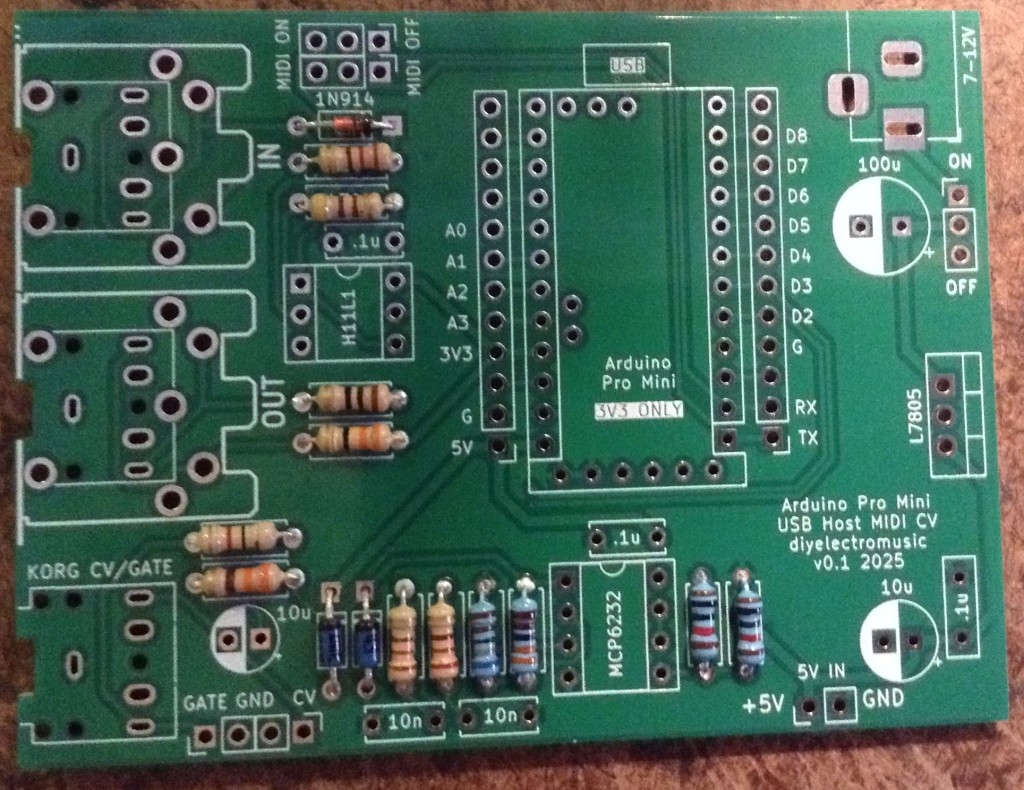
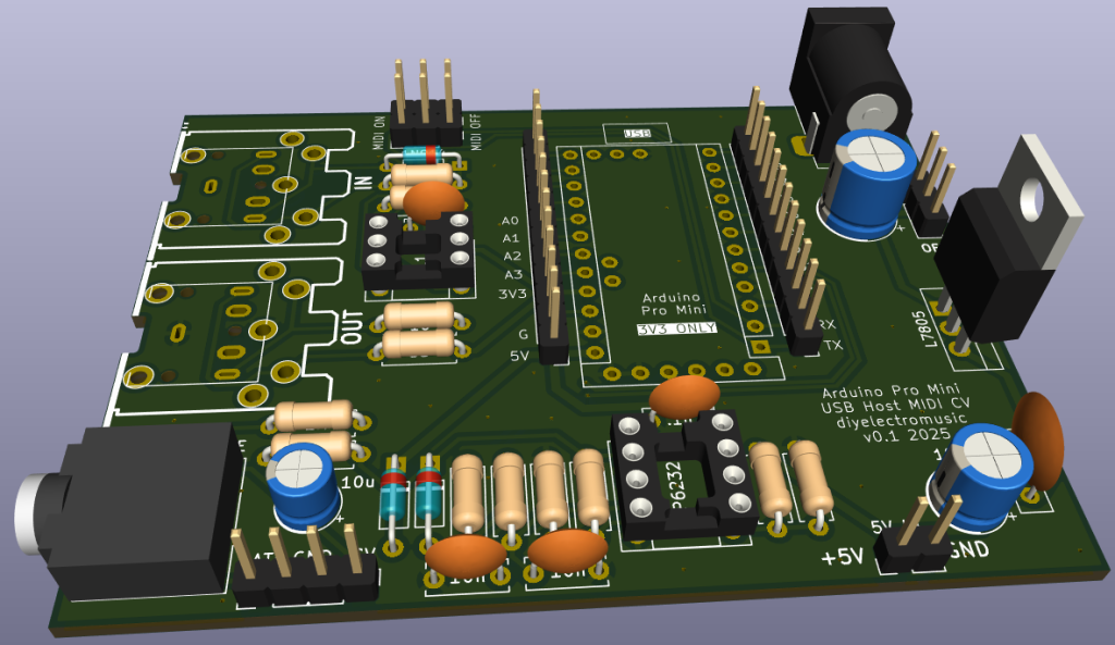
Here are some build photos.
The two 220Ω resistors should be replaced with 1K instead.
If using MIDI TRS sockets, these should be added, along with the CV/Gate socket, next with the (optional) DIP sockets.
I’m going to use MIDI DIN sockets, so they will be left almost to last.
The MIDI on/off is required to disabled MIDI to allow sketch uploading to the Pro Mini. This can be replaced with 2×3 pin headers and jumpers, or if the Pro Mini will be removed for programming, even wire links.
I’m using a DPDT slider switch with a 2×3 2.54mm pitch.
The two 10nF capacitors should be replaced with 100nF capacitors instead.
If using 2x 12-way header sockets for the Arduino, these can be added at the same time as other pin headers next.
I’m planning on soldering my USB Host shield and Pro Mini directly to the board, so the best way to do that seems to be to add the headers to the board, as shown below, then I’ll add the shield and Pro Mini later.
The power circuitry is optional. This allows a 7-12V DC barrel jack (centre positive) to be used to create the required 5V for the Pro Mini and USB.
Alternatively, there is a 5V/GND direct jumper header that may be used instead. This should not be used to power the board if the regulator is fitted, but can be used as a 5V source if required.
Note: as already mentioned, when adding the electrolytic capacitors, the 10uF next to the CV TRS socket should be left out and replaced by a wire link.
The full photo below shows the capacitor present – I had to remove it!
The MIDI DIN sockets, if used, are the last component apart from the Arduino itself.
I will be stacking the USB shield and Pro Mini, so the shield goes on next. Note: there is a track that requires cutting between the VBUS solder pad and the 2K2 resistor as shown below. Note, this track must not be cut between the USB socket and the VBUS pad…
Cutting this track removes the connection between the USB VBUS lines and VCC on the PCB, which is running at 3V3. Once cut, a wire can then be soldered between the VBUS pad and the pin that will eventually connect to the Pro Mini’s VIN pin as shown below.
At this point the Pro Mini can now be added on top. I’ve not used any additional spacers, simply relying on the existing solder on the pin headers (from the USB shield) and the presence of the patch wire to distance the board enough. The pin headers themselves weren’t long enough, for me, to add proper plastic spacers, so I didn’t.
Testing
I recommend performing the general tests described here: PCBs.
The sample application section below lists some sketches that will test the various functions of the board.
An oscilloscope can be used to check the voltage output from the PWM signal.
PCB Errata
There are the following issues with this PCB:
- As already mentioned, there are two issues with the CV output circuit:
- The electrolytic capacitor should be replaced with a wire link.
- The 10nF and 220Ω resistors in the filter should be replaced with 100nF and 1K.
Enhancements:
- The CV and GATE signals are different levels at present. CV is 0-5V; GATE is 0-3.3V. Perhaps they ought both be 5V signals.
Sample Applications
The following GPIO pins are used with this PCB:
D0/D1RX/TX for Serial MIDID2GATE outputD3PWM CV outputD9INT pin for USB Host shieldD10-D13SPI link to USB Host shieldHere are some applications to get started with.
Note: I found that serial MIDI would not work when powered via the programming header, presumably because my programmer was controlling RX/TX. To test MIDI the board had to be powered via the barrel jack or 5V directly.
Also recall that MIDI needs to be OFF in order to upload sketches.
- USB MIDI: USB MIDI monitor code here.
- Serial MIDI IN: Simple MIDI monitor code here.
- Serial MIDI OUT: Examples -> USB Host Shield Library 2.0 -> USBH_MIDI -> USB_MIDI_Converter
- GATE Output: Examples -> 02.Digital -> toneMelody (it just produces a square wave)
- PWM Output: Arduino PWM Sound Output (even though this isn’t for sound!)
For the last two, some minor code changes are required.
For toneMelody, the pin used need changing from pin 8 to pin 2 in the tone() and noTone() calls.
For the PWM output, the following configuration options must be set:
//#define FREQPOT A0
//#define PIN_9_PWM_OUTPUT 1   // Uses Timer 1
#define PIN_3_PWM_OUTPUT 1   // Uses Timer 2
In both the GATE and PWM test, it is actually possible to hook up a speaker via a stereo 3.5mm jack to the CV/GATE TRS socket.
WARNING: If you do this, the speaker will be receiving a 0-5V signal on either the L or R outputs (depending on the test). This is a lot more than a line input signal (which is typically +/- 0.8V) so do not hook this up to standard audio input.
Alternatively, just check the signals via the GATE/CV jumper header with an oscilloscope.
The PWM output should be 0-5V. The GATE output should be 0-3.3V.
Use as a USB to CV/GATE Converter
The CV/GATE TRS output follows the standard set for the Korg Volca Modular (see Korg Volca Notes).
I show how to use this as a USB MIDI interface for a CV/GATE synth here: USB MIDI to Serial and CV/GATE.
IMPORTANT: Do not use this board with your Korg Volcas unless you know what you are doing, are able to validate all signals prior to connection yourself, and happy with the very real possibility that the board might do something that damages the Volca.
I am not an electronics person and will not be responsible for damage to expensive or treasured equipment. I only use cheap or disposable equipment in my own projects.
Closing Thoughts
Adding that capacitor was a case of me running on “autopilot” I think, but that is a straightforward fix, so no real harm done.
At the end of the day, this whole board is a little niche, even by my standards.
But it seems to work well enough that I can get on with writing some proper firmware for it now.
Kevin
#arduinoProMini #cv #korg #midi #pcb #pwm #usbHost #usbHostMidi #volca
Arduino Pro Mini MIDI USB CV PCB Design
This is essentially a version of my Korg Volca Modular MIDI to CV PCB Design merged with my Arduino Pro Mini MIDI USB HOST PCB Design to give me USB MIDI to serial MIDI and CV.
Warning! I strongly recommend using old or second hand equipment for your experiments. I am not responsible for any damage to expensive instruments!
If you are new to electronics and microcontrollers, see the Getting Started pages.
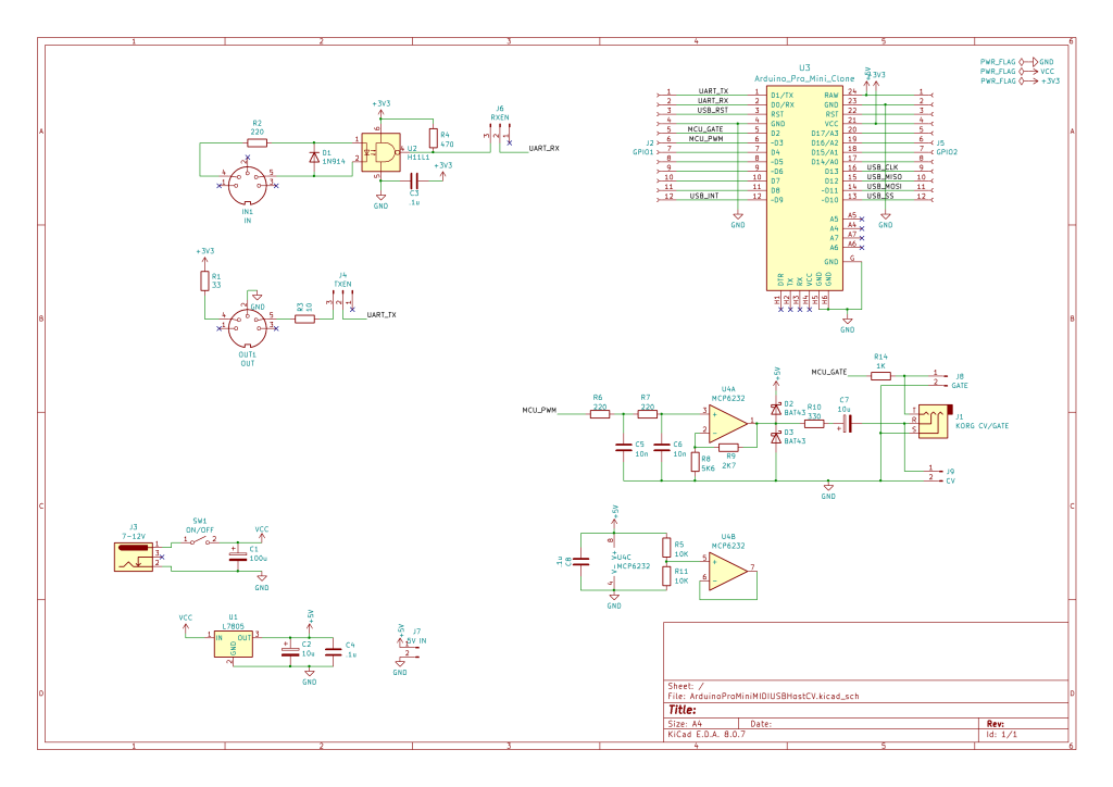
The Circuit
As previously mentioned this is largely a merging of two existing designs. The main elements are:
- Arduino Pro Mini (3V3/8MHz) with optional USB Host Shield already attached.
- 3V3 compatible Serial MIDI IN/OUT circuit.
- 5V power circuit via a 7805 regulator feeding the VIN of the Pro Mini.
- PWM output filter.
- 3V3 to 5V opamp amplifier stage (largely based on HAGIWO’s designs).
- Korg Volca compatible Gate/CV out via a TRS socket.
I’m using a MCP6232 rail-to-rail dual OpAmp, but I’m only using one of them, so apparently good practice dictates normalising the input of the unused OpAmp to ideally the mid-voltage of the power rails, which I’ve done using two resistors as a potential divider.
The OpAmp is set up for a noninverting amplifier aiming for, as I understand things, a gain of 5/3.3 or ~1.51 as follows:
- Non-Inv Gain = 1 + R(feedback) / R(toground) = 1 + 2K9 / 5K6 = 1.51
Note: the capacitor in the PWM output circuit is actually an error. It isn’t required for a CV output.
Also, the CV output is amplified to make it a 0-5V signal, but the GATE output remains a 0-3.3V signal.
A note on the PWM Filter.
The circuit was originally pasted on from somewhere else and I have to confess I didn’t think about the differing nature of a PWM circuit for a control voltage compared to audio.
As such, the stated component values of 220Ω and 10nF, with a cut-off frequency of upwards of 70kHz whilst useful for audio, are pretty useless for a CV. In the actual build, I’ve used values of 1K and 100nF which gives a cutoff frequency of around 1.5kHz.
That will teach me to properly think about my requirement before cutting and pasting in one of my previous circuits 🙂
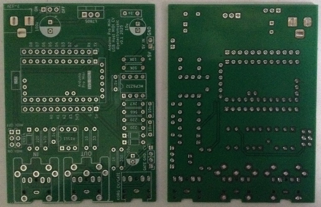
PCB Design
Unlike my last design this one assumes the USB host shield will be fixed to the Pro Mini, keeping the footprint as small as possible.
I’ve allowed for both MIDI DIN and TRS sockets. There is also an option for individual GATE and CV out via jumper headers in addition to the Korg Volca compatible TRS.
I’ve included a MIDI switch with the footprint of a 2×3 set of 2.54mm headers so that could be jumpers or a switch as required. If the Pro Mini is socketed (which isn’t so easy if a USB Host shield is attached, but would be possible with longer pin headers), then the MIDI switch could be omitted. It is only there to disconnect MIDI from the Pro Mini UART when uploading sketches.
There is a bit of space around the 7805 in case a small heatsink is required. There is also the option to power the board directly from a 5V supply via a two-pin jumper header.
The Pro Mini footprint includes the programing header, but this isn’t used on the board and should probably be ignored.
Closing Thoughts
My previous MIDI to CV was code for an ATtiny85, so I’ll need to rewrite the code for the ATMega328 on the Pro Mini to support the USB to Serial MIDI routing in addition to CV and GATE.
Kevin

Der erste Schritt zu meinem neuen Song: Die Entwicklung könnt ihr hier auf YouTube verfolgen.
#volca #volcasample #music #sampling #synthesizer
Channeling creativity through the Volca Drum and Volca FM2 synths - sculpting something bold and captivating. Can’t wait to share this one!
https://youtube.com/shorts/ueCw7mj5gM0?feature=share
#Korg #Volca #MusicProduction #IndieArtist #SynthLife #SynthJourney #NewTrack #ElectronicMusic #CreativeProcess
"Shift Register Random Calvados Voltage"
How about a track made on my 54hp lunchbox #eurorack #modular #synth, with some rhythm also generated by the synth? Using the #Disting Mk4 algorithm F6, the shift register random quantized voltage function and frequency divider for the percussions. #korg #volca #mix compressor used to create part of the rests and syncopation. Food related? Calvados.
#soundcloud #music #minimalist #techno #electronica #livetronica #experimental
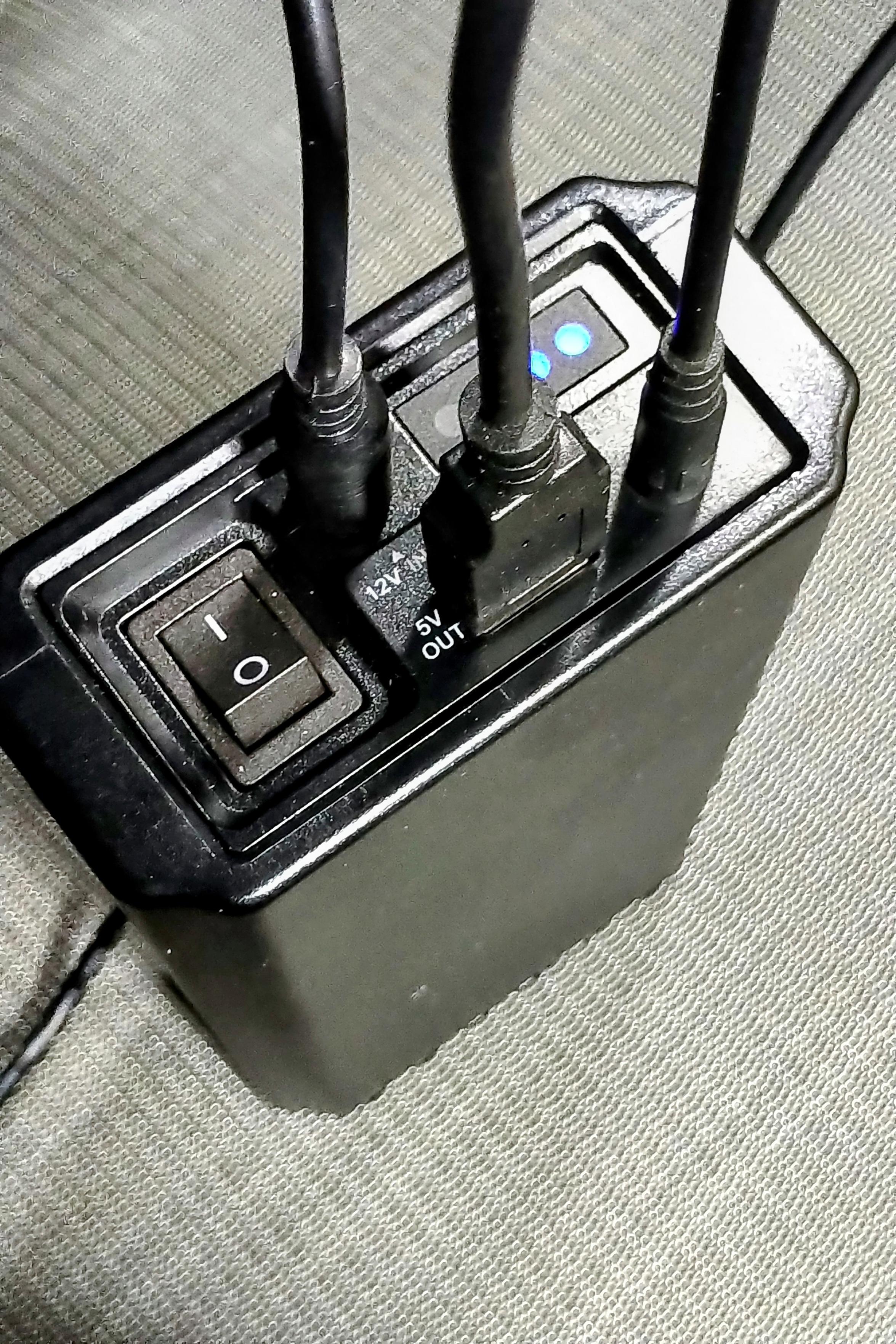
The larger pack (pictured) has 12V (but 5525 instead of 5521, so I need a 5525 to 5521 cable to connect my lunchbox #modular #synth), a USB port and it also has a 9v (+tip) output, 4717. With that, I can run the #korg #volca #mix. Using the right combination of tip adapters, polarity switchers and daisy chain cable, I can run both the #korg #volca #mix mixer (+tip) and guitar pedals (-tip)
"Happy Wasabi Wavetable"
Another #electronic #music track done live on the battery powered 54hp lunchbox #eurorack #modular #synth. Disting Mk4 on wavetable algo, Beehive and uBursts. Sequencing & mod through Pachinko. #2HP Kick, #Bastl Skis w/radio for basic percussions. Added an RD-6 to augment the drums. Final mix through the #Korg #Volca Mix (also powered by the battery pack) sitting in the lunchbox case lid. Listen to it on #soundcloud on my lunchbox playlist:
https://soundcloud.com/francois_dion/happy-wasabi-wavetable?in=francois_dion/sets/lunchbox
New Bandcamp release!
https://iwillfightforyou.bandcamp.com/track/keysfm
you can give it a listen here. I have been proud of this fleeting moment in 2018 when everything everything fell perfectly into place
~~~
#korg #volca #volcafm #volcakeys #synth #bandcamp #release #music
https://iwillfightforyou.bandcamp.com/track/keysfm
you can give it a listen here. I have been proud of this fleeting moment in 2018 when everything everything fell perfectly into place
~~~
#korg #volca #volcafm #volcakeys #synth #bandcamp #release #music

On New Year's Eve 2022 I spent the evening jamming on my volcas.
This is some of it, it's ragged but fun.
welcome to the monkey house - a RadioPhobicSherkPop jam #SoundCloud
https://on.soundcloud.com/7RM2x7HWjCPrMm919
#ElectronicMusic
#Music
#OriginalMusic
#Volca
#Dawless until I edited it in Cubase and added percussion but it still counts I reckon
Sound Design with the Korg Volca Beats
Sound Design with the Korg Volca Keys
Client Info
Server: https://mastodon.social
Version: 2025.04
Repository: https://github.com/cyevgeniy/lmst