#Milestone4 — #IonicScroll
#ModulatingSpirals https://pixelfed.social/p/Splines/792906324854792619
#ReverseEngineer #ImageScans https://pixelfed.social/p/Splines/793215298082967733
#ScrollSurface #scaffolding https://pixelfed.social/p/Splines/793597613908557570
#SecondaryCurves https://pixelfed.social/p/Splines/794105734853818690
#Sweeping with #TertiaryCurves https://pixelfed.social/p/Splines/794203007066866034
#Smoothness with #SurfaceBlend https://pixelfed.social/p/Splines/794868875707070193
Solid #Scroll https://pixelfed.social/p/Splines/795276076797088402
#Milestone3 — #IonicColumn https://pixelfed.social/p/Splines/792803978865652429
#Milestone2 — Classic #IonicEntablature https://pixelfed.social/p/Splines/791021871062069787
#Milestone1 — #IonicPedestal https://pixelfed.social/p/Splines/790752092700055739
#ImageScans

The #secondaryCurves derived in https://pixelfed.social/p/Splines/793641134563617634 with 4 #modulatingSpirals are sufficient for a rough draft when #3DPrinting, but sweeping the scroll surface using these curves still causes subtle wobbles. These wobbles generate undercuts that precludes #CNCMilling with 3-axis machines depending on orientation, and that requires 5-axis #CNC machines instead.
To ameliorate that situation, I added 2 more interstitial frames labeled K and L, where k is 14 units in front of P, and L is 7 units behind Q. The size of K is 58.24 x 81.92 and that of L is 54.88 x 78.72. In other words, K is wider by 2.24 and taller by 1.92 compared to P and Q, while L is narrower by 1.12 and shorter by 1.28 compared to P and Q.
K is offset from P in the front view by 0.64 at top, 1.28 at bottom, 1.44 at left, and 0.80 at right. L is concentric with Q in the front view with top and bottom insets of 0.64 and left and right inset of 0.56. How I derived these is too complicated to discuss within #Pixelfed character limits.
Obviously, the scale factors for the spiral at K are 58.24/112 in X direction and 81.92/128 in Y direction. The scale factors for the spiral at L are 54.88/112 in X direction and 78.72/128 in Y direction.
So, using these 6 modulating spirals, we again identify the tangent points with their respective frames and #project straight lines through these points on the scaffolding surface to get 6 higher-accuracy secondary curves.
The diagram shows 6 blue #primaryCurves we extracted from #imageScans in https://pixelfed.social/p/Splines/793169876757012827 and https://pixelfed.social/p/Splines/793215298082967733 along with 6 new magenta secondary curves. The outlines we extracted from #Vignola’s antique images in 2-dimensions finally leap into 3-dimensions in a modern #CAD tool.
The blue primary curves are no longer needed for this design, but don't discard them. They are beautifully proportioned and can be used in other designs.

#SeeFeelTouchHug
In both #art and #engineering, one must be able to both #see and #feel things that might not be there (yet).
We were able to "see" the outlines of the #scroll surface from #imageScans of #Vignola's sketches in https://pixelfed.social/p/Splines/793169876757012827 and https://pixelfed.social/p/Splines/793215298082967733.
Vignola's images are on a 2-dimensional surface, as are the outlines we extracted from them. We believe the scroll surface also exists, but it is not yet manifest in 3-dimensional space. So, like a visually impaired person, we try to "feel" our way to the scroll surface using the outlines as our #walkingStick.
This diagram is identical to that in https://pixelfed.social/p/Splines/793493316852849994 but with the rear ends of the horizontal #primaryCurves marked with R1, R5, and R3, which are paired with F1, F5, and F3, respectively.
We know that the scroll surface must #touch the tangent points T1, T2, and so on in front, as well corresponding tangent points in the rear (not shown here to reduce clutter).
In https://pixelfed.social/p/Splines/792906324854792619, I mentioned that a scroll starts with a volute in front and is #modulated by as many as six volutes of different shapes and sizes as it reaches the back, with the scroll surface tightly hugging the volutes at EACH contact point in ALL 3 dimensions. In other words, it is not sufficient for the scroll surface to "touch" the #volute #spirals just in the front and rear. It must also "hug" the intermediate #modulatingSpirals. I will first show this technique with 4 modulating spirals using rectangles M, N, P, Q, and R as their frame, and add more later on.
Intuitively, we know that if we use curve F3-R3 as our walking stick on the straight vertical extrusion of that curve, we will feel the scroll surface *somewhere* on that extrusion along every point from front to back. We can narrow it down further by excluding portions above and below as we approach rectangle R in the rear.
From #PrimaryCurves to #SecondaryCurves for classic #IonicScroll
There's a lot to unpack in this diagram. For orientation, first note the 5 rectangles labeled M, N, P, Q, and R that we saw in https://pixelfed.social/p/Splines/792966507797633558, shown here in green.
The 6 blue curves are the primary curves we extracted from #imageScans in https://pixelfed.social/p/Splines/793169876757012827 and https://pixelfed.social/p/Splines/793215298082967733. The front ends of these blue primary curves are marked by points labeled F1 through F6, all of which make contact with the green rectangles of the scroll #scaffolding. The rear ends of the primary curves would be marked similarly by points R1 through R6, but they are not shown here to reduce clutter.
The orange points T1 through T5 mark where the large orange spiral is tangential to rectangles M and N. Point T6 marks the maxima for the second arm of the spiral, with the horizontal tangent shown in magenta.
In https://pixelfed.social/p/Splines/790571135473463588, I said that one way to think about #curveExtraction is to shine an imaginary bright light on an object from behind in a dark room to reveal its silhouette.
It is obvious that the blue primary curves that we extracted from image scans have NO contact with the orange spiral at any point. If you imagine shining a light on an object to #project its outline on a screen behind it, then it should also be obvious that no part of the object will be in contact with the projected outline.
So, here we are faced with the opposite problem. Instead of extracting the outlines from the #scroll, we want to recreate the scroll from the outlines that we extracted from image scans. We know the scroll exists because we can "see" its outline. Yet, like a visually-impaired person, we must "feel" our way to the scroll using the blue outlines as our #walkingStick.
Next, I show how we can feel our way around this scene to recover the secondary curves to reconstruct the scroll surface.
#ReverseEngineer #ImageScans for #restoration.
This is a side view from #Vignola's #RegolaArchitettura at https://archive.org/details/gri_33125008229458/page/n39/mode/2up.
We recover the essential geometry of #primaryCurves using #curveFitting by trial and error — a human endeavor by "eye" and heuristics — not to be confused with mathematical curve fitting by regression analysis.
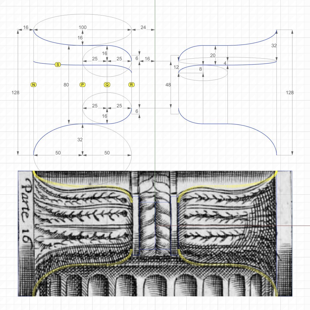
The heights of rectangles labeled N, P, Q, and R are 128, 80, 80, and 48, respectively. P is halfway between N and R, and Q is halfway between P and R.
The curve labeled S is the counterpart to the curve labeled O in the previous post. The purpose of these curves will be explained when we derive the #secondaryCurves from the primary curves.
For now, just note that curve O in the previous post is derived by simple proportion arithmetic. Width of N is 112 units and width of R is 28 units [https://pixelfed.social/p/Splines/793169876757012827]. Since the gap between start of curve O and the curve closest to it is 32 units at the front, the gap at the rear is 32*28/112 = 8, and 16 in the middle.
Curve S is derived in a slightly different manner because, unlike curve O where we knew the starting point, we know neither the start nor the end of curve S. Instead, we look at another clue that Vignola left for us — The 4 long leaves emanating from the rear and spreading towards the front on each bell shape. So we divide the front height of N and rear height of R into 4, giving us the start of S at 32 units from the top (miraculously in agreement with the start of curve O) in front and 12 units in the rear.
The top profile curve does not seem to "fit" Vignola's sketch. First, this is a hand sketch. Second, I tried to fit the curve more closely, but the design broke down later. Third, realize that if we fit the curve more closely to what's in the sketch, this will be the ONLY curve to have a tangent at the inflection point (switch from convex to concave) that is neither horizontal nor vertical.
This is a side view from #Vignola's #RegolaArchitettura at https://archive.org/details/gri_33125008229458/page/n39/mode/2up.
We recover the essential geometry of #primaryCurves using #curveFitting by trial and error — a human endeavor by "eye" and heuristics — not to be confused with mathematical curve fitting by regression analysis.
The heights of rectangles labeled N, P, Q, and R are 128, 80, 80, and 48, respectively. P is halfway between N and R, and Q is halfway between P and R.
The curve labeled S is the counterpart to the curve labeled O in the previous post. The purpose of these curves will be explained when we derive the #secondaryCurves from the primary curves.
For now, just note that curve O in the previous post is derived by simple proportion arithmetic. Width of N is 112 units and width of R is 28 units [https://pixelfed.social/p/Splines/793169876757012827]. Since the gap between start of curve O and the curve closest to it is 32 units at the front, the gap at the rear is 32*28/112 = 8, and 16 in the middle.
Curve S is derived in a slightly different manner because, unlike curve O where we knew the starting point, we know neither the start nor the end of curve S. Instead, we look at another clue that Vignola left for us — The 4 long leaves emanating from the rear and spreading towards the front on each bell shape. So we divide the front height of N and rear height of R into 4, giving us the start of S at 32 units from the top (miraculously in agreement with the start of curve O) in front and 12 units in the rear.
The top profile curve does not seem to "fit" Vignola's sketch. First, this is a hand sketch. Second, I tried to fit the curve more closely, but the design broke down later. Third, realize that if we fit the curve more closely to what's in the sketch, this will be the ONLY curve to have a tangent at the inflection point (switch from convex to concave) that is neither horizontal nor vertical.
#ReverseEngineer #ImageScans
We now dig into the archives and resurface old sketches for #restoration. This one is from #Vignola's #RegolaArchitettura at https://archive.org/details/gri_33125008229458/page/n39/mode/2up. This lavishly illustrated book with copious notes that also flaunt his #calligraphy was written (in Italian) when America was still a British colony. The book went out of copyright a long time ago.
Straighten the image as much as you can in an image editor and crop it before bringing it into a #CAD tool.
Then, stare at the image for a while and squint occasionally until you "see" crucial features and patterns emerge, while ignoring the "noise."
Finally, try #curveFitting with the simplest of curves — straight lines, circular arcs, ellipse, and so on to get as close an approximation as possible. Remember that with hand-drawn sketches, the fit will rarely be perfect. So use some structure as a guide or #scaffolding as I laid out in https://pixelfed.social/p/Splines/792966507797633558.
In the top left of the diagram, I show the measurements that I was satisfied with after a lengthy process of trial and error because the numbers comport with my understanding of the proportions the original designers intended — many, but not all of which are documented in #Scarlata's #PracticalArchitecture with #VignolaProportions in tabular form.
For measurements that are missing, use plausible heuristics to fill in the blanks and try to justify your choices using simple rules. In this case, the bedrock rules are:
1. The entire #volute is exactly µ = 144 units wide, including #ArcZero, which extends 32 units beyond the portion of the volute that is actually used in the design.
2. The portion of the volute that is actually used in the design is 112 units wide, same as the height of the unadorned #capital.
3. Width of the #scroll bell shape as seen from the bottom is 112 units in front, 56 units in the middle and 28 units in the rear — all in #geometricSequence.
Client Info
Server: https://mastodon.social
Version: 2025.07
Repository: https://github.com/cyevgeniy/lmst