#Milestone4 — #IonicScroll
#ModulatingSpirals https://pixelfed.social/p/Splines/792906324854792619
#ReverseEngineer #ImageScans https://pixelfed.social/p/Splines/793215298082967733
#ScrollSurface #scaffolding https://pixelfed.social/p/Splines/793597613908557570
#SecondaryCurves https://pixelfed.social/p/Splines/794105734853818690
#Sweeping with #TertiaryCurves https://pixelfed.social/p/Splines/794203007066866034
#Smoothness with #SurfaceBlend https://pixelfed.social/p/Splines/794868875707070193
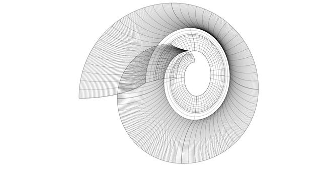
Solid #Scroll https://pixelfed.social/p/Splines/795276076797088402
#Milestone3 — #IonicColumn https://pixelfed.social/p/Splines/792803978865652429
#Milestone2 — Classic #IonicEntablature https://pixelfed.social/p/Splines/791021871062069787
#Milestone1 — #IonicPedestal https://pixelfed.social/p/Splines/790752092700055739
#SecondaryCurves
Continuation of https://pixelfed.social/p/Splines/794199123072358090
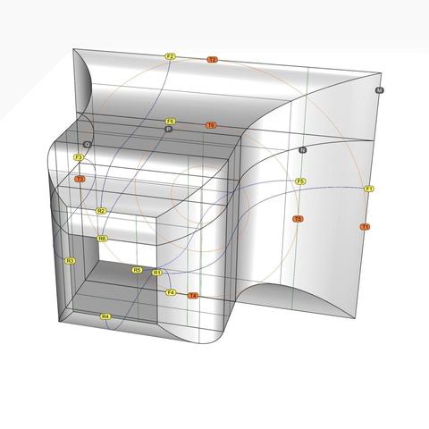
After you have rebuilt all the #spiral arcs as well as the projected #secondaryCurves into #tertiaryCurves, it is finally time to sweep the scroll surface, but remember to do it one section at a time.
Use one section of a spiral arc and the corresponding arc in the next interstitial as #railCurves. Then, #sweepTwoRails, using one section of the tertiary curves on each end of the rails.
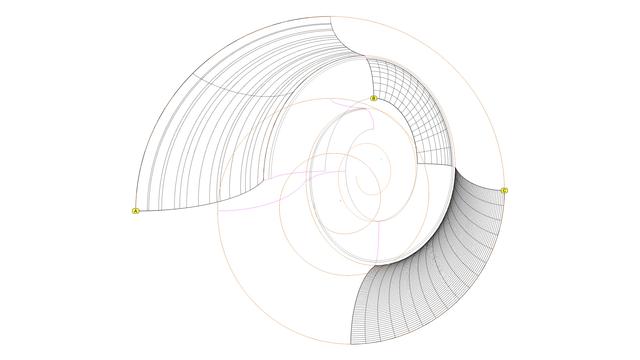
This diagram shows 5 sections of the swept surfaces in front and 5 sections in the back.
The remaining ones will be built similarly but require further processing to make the whole surface smooth.
With the #secondaryCurves derived from #primaryCurves in https://pixelfed.social/p/Splines/794105734853818690, we are almost ready to sweep the #scroll surface. I say "almost" because there is at least one more refinement needed before we can use any of these curves.
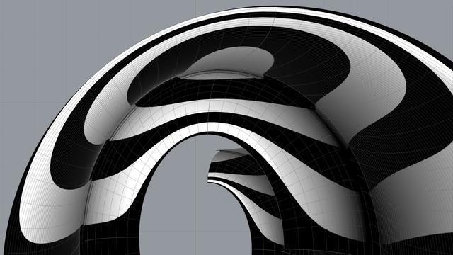
Look at the front view of three sections of the scroll surface labeled A, B, and C, and you will see a qualitative difference among them. Surface A appears crude and surface C appears refined, while surface B lies somewhere in between. While B and C are both acceptable, A is not.
The difference is due to two factors — the nature of the curves themselves and the degree of precision used.
Surface A is built using the circular arc sections for #volute #spiral (original and scaled) as #railCurves and the secondary curve sections as #sweepingCurves. The nature of the two sets of curves is different. Straight lines are 1st-degree curves, #circular or #conic sections (including ellipse) are 2nd-degree curves, but the projected sweeping curves (secondary curves) are 3rd-degree #NURBS curves.
Sweeping 3rd-degree NURBS curves along 2nd-degree arcs does not produce a salubrious effect. So we #rebuild the arcs into a 3rd-degree curve using the #CAD tool. When we do that, we are able to control how close the rebuilt curve should be to the original arcs in terms of precision.
I rebuilt each arc in the spirals using 16 subsections, and the effect is visible in surface C.
Look at surface A again. The cross-section arcs appear unevenly spaced compared to those of the other surface sections. To fix that, I also rebuilt the projected NURBS curves (secondary curves) to obtain what I call #tertiaryCurves.
For the frontmost sections, I rebuilt the sweeping curves using 64 subsections, and for the rear sections, I rebuilt them with 8 subsections.
Experiment with what produces pleasing results, but remember that higher precision curves require more processing time as well as more storage space.
The #secondaryCurves derived in https://pixelfed.social/p/Splines/793641134563617634 with 4 #modulatingSpirals are sufficient for a rough draft when #3DPrinting, but sweeping the scroll surface using these curves still causes subtle wobbles. These wobbles generate undercuts that precludes #CNCMilling with 3-axis machines depending on orientation, and that requires 5-axis #CNC machines instead.
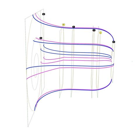
To ameliorate that situation, I added 2 more interstitial frames labeled K and L, where k is 14 units in front of P, and L is 7 units behind Q. The size of K is 58.24 x 81.92 and that of L is 54.88 x 78.72. In other words, K is wider by 2.24 and taller by 1.92 compared to P and Q, while L is narrower by 1.12 and shorter by 1.28 compared to P and Q.
K is offset from P in the front view by 0.64 at top, 1.28 at bottom, 1.44 at left, and 0.80 at right. L is concentric with Q in the front view with top and bottom insets of 0.64 and left and right inset of 0.56. How I derived these is too complicated to discuss within #Pixelfed character limits.
Obviously, the scale factors for the spiral at K are 58.24/112 in X direction and 81.92/128 in Y direction. The scale factors for the spiral at L are 54.88/112 in X direction and 78.72/128 in Y direction.
So, using these 6 modulating spirals, we again identify the tangent points with their respective frames and #project straight lines through these points on the scaffolding surface to get 6 higher-accuracy secondary curves.
The diagram shows 6 blue #primaryCurves we extracted from #imageScans in https://pixelfed.social/p/Splines/793169876757012827 and https://pixelfed.social/p/Splines/793215298082967733 along with 6 new magenta secondary curves. The outlines we extracted from #Vignola’s antique images in 2-dimensions finally leap into 3-dimensions in a modern #CAD tool.
The blue primary curves are no longer needed for this design, but don't discard them. They are beautifully proportioned and can be used in other designs.
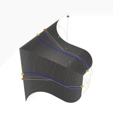
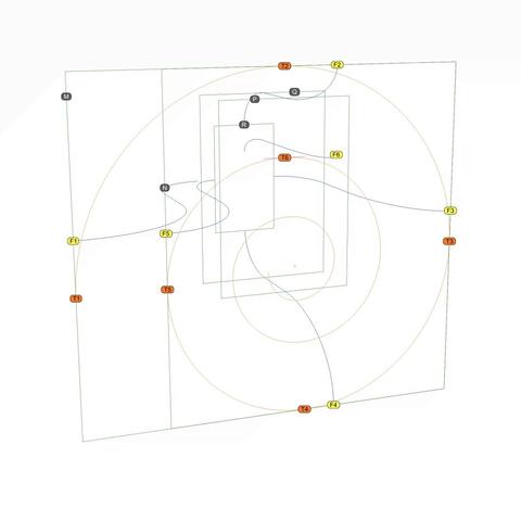
Perspective view of #scroll #scaffolding to create #secondaryCurves from #primaryCurves. See https://pixelfed.social/p/Splines/793597613908557570 for backstory.
Green rectangles M, N, P, Q, and R are shown with orange #volute #spirals non-uniformly scaled for their respective frames. Original spiral inside M is unchanged.
To reduce clutter, I show only two sides and two primary curves, F2-R2 and F3-R3. Neither of these curves touches any of the volutes at any point, but they are used as #walkingSticks to create the surfaces which help us locate the tangent curves.
To accomplish that, first locate all tangent points for orange spirals and their respective green frames. I labeled those for the largest spiral in an earlier post as T1 through T6. Here, I show only T2 and T3. The other points of tangency for the top and right sides can be seen if you follow the thick green lines. I didn't label them to reduce clutter, but each endpoint and each kink is a point of contact and tangency between a spiral and its frame.
Our goal is to shift F2 to T2 and F3 to T3, with similar shifts at each point of tangency on the green line.
To do that, #project the green line through T2 on the top surface to get the magenta curve on top. Think of the green line as a thin "rope" on which you shine a bright light from top to get the magenta line on the top surface. Both, the green and magenta lines touch the volutes, but neither touches the blue line at any point. Additionally, the top magenta line touches the top surface at EVERY point. When the blue line through F2 and the magenta line through T2 are viewed from a side, they are indistinguishable. We have found a secondary curve faithful to a primary curve.
Using the same approach, project the green "rope" passing through T3 on the side surface to obtain the secondary magenta curve passing through T3.
Blue primary curves and green straight lines have served their purpose and are no longer needed. Repeat for tangents on other sides.
Refer to https://pixelfed.social/p/Splines/793554853964898442 for the backstory on this post.
This is a perspective view showing #scroll #scaffolding surfaces #extruded from #primaryCurves F1-R1, F2-R2,…. Be sure to follow these blue curves from back to front and then back again.
Metaphorically speaking, we want to use these blue curves as #walkingSticks to find the curves that meet at the front tangent points T1 through T6 and corresponding tangent point in the rear (not shown), WHILE remaining faithful to the original curves we extracted from #Vignola's original sketches.
This means that the point F1 should somehow move toward T1, F2 toward T2, and so on, with corresponding movements on the rear rectangle, yielding us 6 new #secondaryCurves.
Being "faithful" to the original means that when secondary curves derived from horizontal #primaryCurves are viewed from the top, corresponding curves are indistinguishable from each other, even though they are clearly different curves with distinct trajectories. Secondary curves derived from vertical primary curves must be indistinguishable from each other when viewed from a side.
In order to accomplish this feat, we need the remaining #volute tangent points on rectangles P, Q, and R. That means we first need the corresponding volutes that are used to #modulate the scroll surface.
In https://pixelfed.social/p/Splines/792616677005177924, we used the #scale operation to scale the original volute down from 3x to match the scale of our model using a #uniformScaling factor of 0.33333333.
In https://pixelfed.social/p/Splines/792966507797633558, we can see that the frame rectangles Q and R have independent scaling factors that are different in the X and Y direction. So here we use #nonuniformScaling.
To get the modulating volute for Q, scale the original volute by 56/112 in X direction and 80/128 in Y direction. Scale factors for the modulating volute at R are 28/112 in X direction and 48/128 in Y direction. P is same as Q.
From #PrimaryCurves to #SecondaryCurves for classic #IonicScroll
There's a lot to unpack in this diagram. For orientation, first note the 5 rectangles labeled M, N, P, Q, and R that we saw in https://pixelfed.social/p/Splines/792966507797633558, shown here in green.
The 6 blue curves are the primary curves we extracted from #imageScans in https://pixelfed.social/p/Splines/793169876757012827 and https://pixelfed.social/p/Splines/793215298082967733. The front ends of these blue primary curves are marked by points labeled F1 through F6, all of which make contact with the green rectangles of the scroll #scaffolding. The rear ends of the primary curves would be marked similarly by points R1 through R6, but they are not shown here to reduce clutter.
The orange points T1 through T5 mark where the large orange spiral is tangential to rectangles M and N. Point T6 marks the maxima for the second arm of the spiral, with the horizontal tangent shown in magenta.
In https://pixelfed.social/p/Splines/790571135473463588, I said that one way to think about #curveExtraction is to shine an imaginary bright light on an object from behind in a dark room to reveal its silhouette.
It is obvious that the blue primary curves that we extracted from image scans have NO contact with the orange spiral at any point. If you imagine shining a light on an object to #project its outline on a screen behind it, then it should also be obvious that no part of the object will be in contact with the projected outline.
So, here we are faced with the opposite problem. Instead of extracting the outlines from the #scroll, we want to recreate the scroll from the outlines that we extracted from image scans. We know the scroll exists because we can "see" its outline. Yet, like a visually-impaired person, we must "feel" our way to the scroll using the blue outlines as our #walkingStick.
Next, I show how we can feel our way around this scene to recover the secondary curves to reconstruct the scroll surface.
#ReverseEngineer #ImageScans for #restoration.
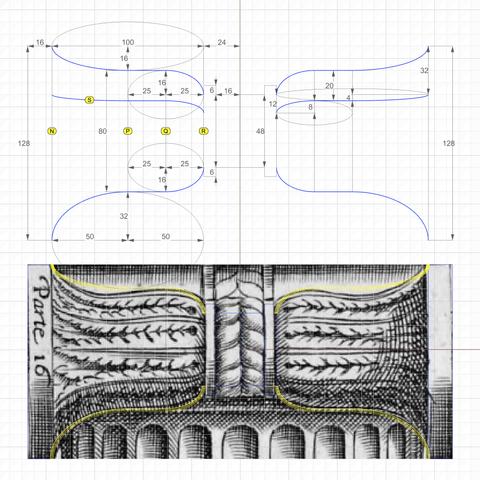
This is a side view from #Vignola's #RegolaArchitettura at https://archive.org/details/gri_33125008229458/page/n39/mode/2up.
We recover the essential geometry of #primaryCurves using #curveFitting by trial and error — a human endeavor by "eye" and heuristics — not to be confused with mathematical curve fitting by regression analysis.
The heights of rectangles labeled N, P, Q, and R are 128, 80, 80, and 48, respectively. P is halfway between N and R, and Q is halfway between P and R.
The curve labeled S is the counterpart to the curve labeled O in the previous post. The purpose of these curves will be explained when we derive the #secondaryCurves from the primary curves.
For now, just note that curve O in the previous post is derived by simple proportion arithmetic. Width of N is 112 units and width of R is 28 units [https://pixelfed.social/p/Splines/793169876757012827]. Since the gap between start of curve O and the curve closest to it is 32 units at the front, the gap at the rear is 32*28/112 = 8, and 16 in the middle.
Curve S is derived in a slightly different manner because, unlike curve O where we knew the starting point, we know neither the start nor the end of curve S. Instead, we look at another clue that Vignola left for us — The 4 long leaves emanating from the rear and spreading towards the front on each bell shape. So we divide the front height of N and rear height of R into 4, giving us the start of S at 32 units from the top (miraculously in agreement with the start of curve O) in front and 12 units in the rear.
The top profile curve does not seem to "fit" Vignola's sketch. First, this is a hand sketch. Second, I tried to fit the curve more closely, but the design broke down later. Third, realize that if we fit the curve more closely to what's in the sketch, this will be the ONLY curve to have a tangent at the inflection point (switch from convex to concave) that is neither horizontal nor vertical.
The classic #IonicScroll is the most complex of all components in the #IonicOrder mainly because it is poorly documented, if at all, and even poorly understood. It is as if the classical architects deliberately concealed its enigmatic design secrets within the confines of a smooth elegant shell that could only be revealed after intense study and analysis.
I got this impression because I spent years searching for credible and actionable documentation on how to recreate this beautiful design in a #CAD tool. In the Age of Internet and Social Media, my web searches always disappointed me because the results lacked something vital in one respect or another. Over the years, I created hundreds of versions of the scroll that looked so perfect and pleasing that I thought I had cracked it, only to find some flaw or another in my work.
So, it is with caution that I present my work on the scroll in the hopes that someone will build upon this knowledge and either validate the design, or correct it and share it with me and the rest of the world.
Looking back at my progress, I'm now surprised at how remarkably simple and elegant the design is that defied familiar geometrical construction techniques I had been using until now.
As I mentioned in my introductory post, this design can be recreated by drawing simple 2-dimensional lines and circular arcs, but instead of just #primaryProfileCurves, we will use up to three additional sets of curves — #secondaryCurves, #tertiaryCurves, and #quaternaryCurves — each derived from the previous set.
I extracted the #primaryCurves after a lengthy trial-and-error process that involved #curveFitting image scans from #Vignola’s book, #RegolaArchitettura. I had to #reverseEngineer the details because the measurements have either been lost, or are locked away in some library.
Even though we start with lines and arcs, the end results are always #NURBS curves and surfaces, but everything is done by the CAD tool, and no additional math is needed.
Client Info
Server: https://mastodon.social
Version: 2025.04
Repository: https://github.com/cyevgeniy/lmst

