#Milestone9 - #ArcadeIntercolumniation #Keystone and #Modillion
#Arch without Pedestal https://pixelfed.social/p/Splines/803615973439041638
#Arch with #Pedestal and Keystone https://pixelfed.social/p/Splines/804537414363507454
#Keystone and #Dentil Details https://pixelfed.social/p/Splines/804548474524642209
#Modillion Details https://pixelfed.social/p/Splines/805587292338863257
#ModernEntablature with Detail https://pixelfed.social/p/Splines/805607059171193759
#Milestone8 - #SimpleIntercolumniation https://pixelfed.social/p/Splines/803106316515798367
#Milestone7 - Complete #IonicOrder https://pixelfed.social/p/Splines/800050647761776920
#Milestone6 — #Braids #3StrandBraids https://pixelfed.social/p/Splines/799602946527813102
#Milestone5 — #EggsAndDarts https://pixelfed.social/p/Splines/797069447808333887
#Milestone4 — #IonicScroll https://pixelfed.social/p/Splines/795361973789834465
#Milestone3 — #IonicColumn https://pixelfed.social/p/Splines/792803978865652429
#Milestone2 — Classic #IonicEntablature https://pixelfed.social/p/Splines/791021871062069787
#Milestone1 — #IonicPedestal https://pixelfed.social/p/Splines/790752092700055739
#IonicColumn

#Milestone8 - #SimpleIntercolumniation
Floor Plan of archetypal Greek Temple https://pixelfed.social/p/Splines/803021258359555093
Front and back #intercolumniation https://pixelfed.social/p/Splines/803076419096100108
Side intercolumniation https://pixelfed.social/p/Splines/803089629244302486
#Milestone7 - Complete #IonicOrder https://pixelfed.social/p/Splines/800050647761776920
#Milestone6 — #Braids #3StrandBraids https://pixelfed.social/p/Splines/799602946527813102
#Milestone5 — #EggsAndDarts https://pixelfed.social/p/Splines/797069447808333887
#Milestone4 — #IonicScroll https://pixelfed.social/p/Splines/795361973789834465
#Milestone3 — #IonicColumn https://pixelfed.social/p/Splines/792803978865652429
#Milestone2 — Classic #IonicEntablature https://pixelfed.social/p/Splines/791021871062069787
#Milestone1 — #IonicPedestal https://pixelfed.social/p/Splines/790752092700055739

#Milestone7 - Complete #IonicOrder with fluted and unadorned #IonicColumn with details of #decorativeElements
#Milestone6 — #Braids #3StrandBraids https://pixelfed.social/p/Splines/799602946527813102
#Milestone5 — #EggsAndDarts https://pixelfed.social/p/Splines/797069447808333887
#Milestone4 — #IonicScroll https://pixelfed.social/p/Splines/795361973789834465
#Milestone3 — #IonicColumn https://pixelfed.social/p/Splines/792803978865652429
#Milestone2 — Classic #IonicEntablature https://pixelfed.social/p/Splines/791021871062069787
#Milestone1 — #IonicPedestal https://pixelfed.social/p/Splines/790752092700055739

#IonicColumn #Flutes
In https://pixelfed.social/p/Splines/799864068250003272 I mentioned rounding off the radius of the bottom circle, but you don't have to. #CAD tools are perfectly happy working with 15.0728 or even higher precision as they are with 15.
After placing the two circles as described in that post, use the full #primaryProfileCurve of the shaft from https://pixelfed.social/p/Splines/791794072490907090 as a #sweepingRail and the two circles for the flutes as the #sweepingCurves, and #sweepOneRail for the body of a single flute. Close #planarHoles on both ends to get an #airtight solid.
Then draw a sphere at the center of the top circle using the same radius as the circle, and perform a #booleanUnion between the sphere and the flute body.
If you want a round bottom for the flute, repeat the sphere at the center of the larger circle using the same radius (15.0 or 15.0728) and perform another boolean union to get one flute.
Switch to the top view and make 24 copies of the flute (including the original) centered at the column axis and #group the 24 flutes.
Finally, perform a #booleanDifference with the flutes group on a copy of the solid #unadornedShaft to get a fluted variant.
The result is a column shaft with flutes carved out. Save the flutes separately for future reuse.
This concludes the entire #IonicOrder, including all #decorativeElements.
Now we pause and reflect: The whole exercise seemed like one of #art and #sculpture. Where is the #architecture in all of this?
Without a ceiling or a roof, there is no building. Without additional columns or walls, there is no ceiling. So, while we have completed the Ionic Order itself, we only have the first #buildingBlock — a single column.
Next step is to repeat the columns to create a #colonnade, which together with supporting walls or additional colonnades can support a ceiling.
Just like with everything else in design, there are rules of proportion for #intercolumniation, or space between columns.
#IonicColumn #Flutes
This diagram shows the 2D geometry of an #Ionic #flute. The larger blue circle shows the flute outline near the #base of the #column. The smaller blue circle shows the flute outline near the #neck of the #shaft. Both subtend a 12° angle at the center of the column.
Like an egg in the #EggsAndDarts motif, a flute must be centered on the column axis when viewed directly from the front, back, or the sides. This is why the 12° are split into 6° on either side of the X axis. The center of the larger circle is µ = 144 units from the origin on the X axis. The center of the smaller circle is 5/6 of µ, or 120 units from the origin.
In https://pixelfed.social/p/Splines/799340150182400358, I mentioned working at sub-micron precision, and you might wonder where that came from when we have been using abstract units like µ without specifying any physical units. My apologies for not making it clear that I had assumed 1 unit was equal to 1 mm. If that assumption holds, then µ = 144 mm gives a total order height of 4104 mm, that is 13.46 ft. At smaller scales, the precision is even higher than 1/10 of a micron.
With that said, here the radius of the larger circle is 15.0728 units and that of the smaller circle is 12.5606 units, with sub-micron precision if 1 unit = 1 mm.
Refer to https://pixelfed.social/p/Splines/791399680747885646 and place the center of the smaller circle exactly at point J on the neck line. Later we will draw a sphere at the same location with the same radius.
If you want a flat bottom for flutes, place the center of the larger circle at exactly 28 units (12 for the #fillet and 16 for the #cavetto or #conge) above point A in that figure. If you want a round bottom, then further move the larger circle up by the size of its radius.
Nobody would quibble if you used a radius of 15 units instead of 15.0728 units, but it would make it easier to switch from flat to round bottom or vice-versa by simply moving the circle up or down 15 units.

#IonicColumn
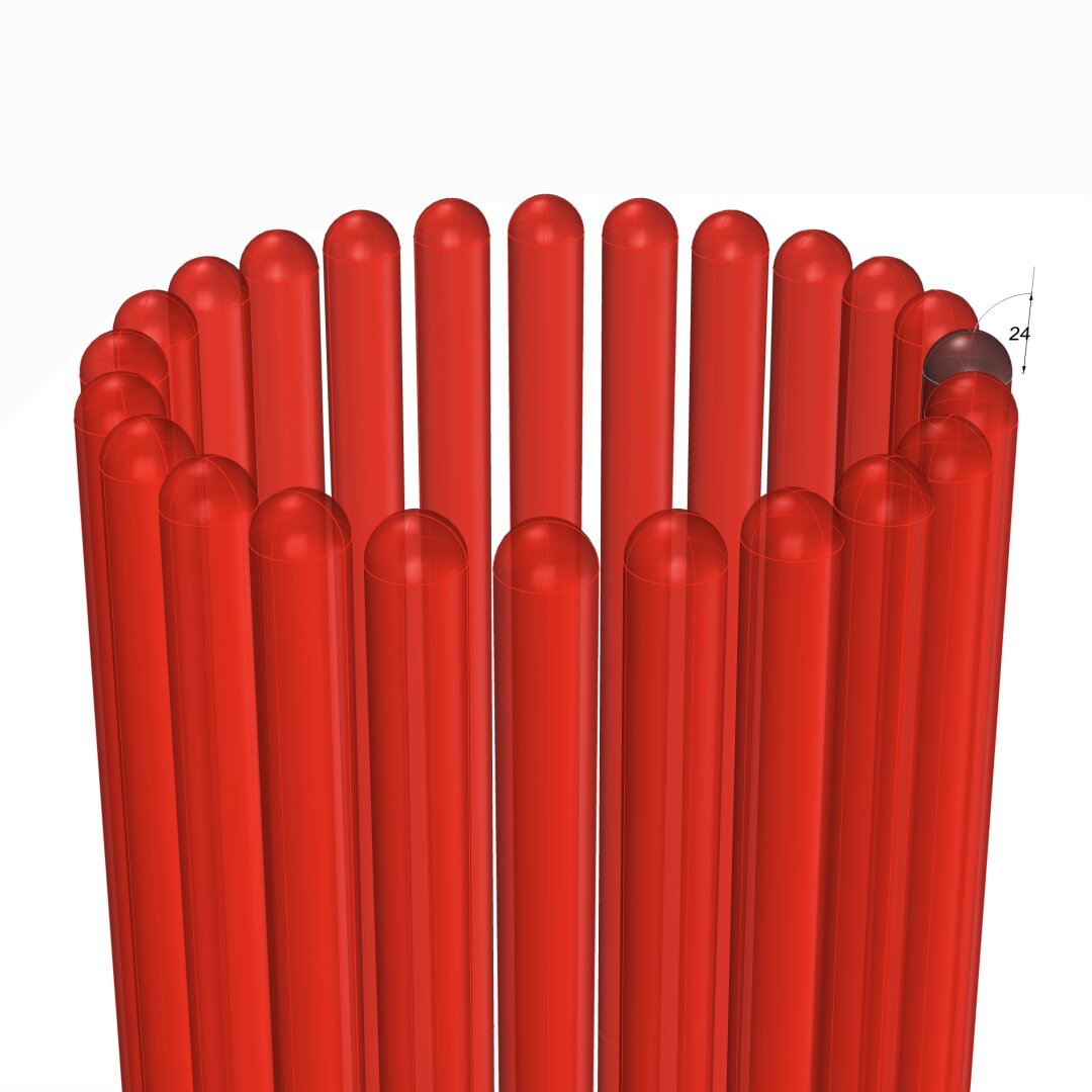
#Flutes have a different configuration in the #IonicOrder than they do in the #DoricOrder. In #Doric, the flutes run right next to each other, dividing the circumference of the column into 24 equal sectors, or 15° each.
In #Ionic, there is a small gap between the flutes. This gap used to vary, but over time, Ionic designers seemed to have settled and standardized the measurements by splitting 15° in 4:1 ratio, giving 12° to a flute and 3° to the gap between flutes.
Because of this standardization, there would seem to be little room for variants, but there is. In his #RegolaArchitettura [see https://archive.org/details/gri_33125008229458/page/n37/mode/2up], #Vignola documented flutes with hemispherical tops but flat bottoms, as shown in the image here.
However, it is acceptable to have hemispheres at both top and bottom as long as they are consistently used within a #colonnade or #arcade.
Flute geometry is interesting. Just like the #IonicColumn #shaft, a flute also gradually tapers as it rises from bottom to top. Additionally, it bends along the shaft surface due to #entasis [see https://pixelfed.social/p/Splines/791794072490907090]. In other words, flutes hug the column shaft.
Unlike other decorative elements like #eggsAndDarts and #3StrandBraids, flutes are #subtractive, not #additive to the rest of the design. In other words, we have to carve the flutes out instead of adding them to the design.

#Milestone6 — #Braids #3StrandBraids
#Sinusoid from #Helix https://pixelfed.social/p/Splines/797893262102038801
Braid Geometry https://pixelfed.social/p/Splines/797916882329430160
Braid Strand https://pixelfed.social/p/Splines/798252244743520392
Braid Assembly https://pixelfed.social/p/Splines/799340150182400358
Braid #FlowOnSurface https://pixelfed.social/p/Splines/799514176049543252
#Milestone5 — #EggsAndDarts https://pixelfed.social/p/Splines/797069447808333887
#Milestone4 — #IonicScroll https://pixelfed.social/p/Splines/795361973789834465
#Milestone3 — #IonicColumn https://pixelfed.social/p/Splines/792803978865652429
#Milestone2 — Classic #IonicEntablature https://pixelfed.social/p/Splines/791021871062069787
#Milestone1 — #IonicPedestal https://pixelfed.social/p/Splines/790752092700055739

#Milestone5 — #EggsAndDarts
Egg 2D https://pixelfed.social/p/Splines/796857354690493749
Dart 2D https://pixelfed.social/p/Splines/796961505955555432
Egg and Dart 3D https://pixelfed.social/p/Splines/797038670230603707
Flow on ovolo surface https://pixelfed.social/p/Splines/797060809462854953
#Milestone4 — #IonicScroll https://pixelfed.social/p/Splines/795361973789834465
#Milestone3 — #IonicColumn https://pixelfed.social/p/Splines/792803978865652429
#Milestone2 — Classic #IonicEntablature https://pixelfed.social/p/Splines/791021871062069787
#Milestone1 — #IonicPedestal https://pixelfed.social/p/Splines/790752092700055739

#EggsAndDarts continuation from https://pixelfed.social/p/Splines/796961505955555432
The slab height depends on the roundness of the egg and whether we have a concave design or not. If we are using a concave base, then top half of the egg is eliminated. For a fully round egg, that means the concave variant must scoop out up to 16 units deep. The dart slab will match the egg slab in depth.
To create the 3-dimensional shape of the dart, first #rotate the fin profile 90° in 3D space along the straight line at the bottom of the fin so that the rotated profile is perpendicular to the two #sweepRails for the dart.
Using the two sweep rails and the perpendicular fin profile, #sweepTwoRails to develop the surface of the dart. Remember to close the planar hole at the end of the fin to get a solid #airtight object. As always, check for #nakedEdges and #nonmanifoldEdges to stave off problems later.
#Extrude the bottom of the dart until it is flush with the bottom of the oval slab.
Two details worth noting in the dart design are:
1. The most exaggerated portions of the dart fin are sliced off when the eggs are sliced. After slicing, the size of the fin is roughly in proportion to the rims of the eggs on both sides.
2. There is a gap between the dart arrow and the oval slab. See the gap between points R and T in https://pixelfed.social/p/Splines/796961505955555432. This gap is necessary and will automatically close when we transfer the egg and dart to the #doublyCurved surface of the #ovolo on the #capital of the #IonicColumn. That is because the Ovolo is shaped like a bowl whose top has a bigger radius than the bottom. As a result, the motif will be warped, and its bottom will be condensed to fit the smaller radius at the bottom, closing the gap in the process.
If you plan to use the eggs and darts motif on a linear surface where there is no warping, experiment with the arrow and tip for a pleasing result.

#Milestone4 — #IonicScroll
#ModulatingSpirals https://pixelfed.social/p/Splines/792906324854792619
#ReverseEngineer #ImageScans https://pixelfed.social/p/Splines/793215298082967733
#ScrollSurface #scaffolding https://pixelfed.social/p/Splines/793597613908557570
#SecondaryCurves https://pixelfed.social/p/Splines/794105734853818690
#Sweeping with #TertiaryCurves https://pixelfed.social/p/Splines/794203007066866034
#Smoothness with #SurfaceBlend https://pixelfed.social/p/Splines/794868875707070193
Solid #Scroll https://pixelfed.social/p/Splines/795276076797088402
#Milestone3 — #IonicColumn https://pixelfed.social/p/Splines/792803978865652429
#Milestone2 — Classic #IonicEntablature https://pixelfed.social/p/Splines/791021871062069787
#Milestone1 — #IonicPedestal https://pixelfed.social/p/Splines/790752092700055739

#Milestone3 — #IonicColumn
#VignolaBase and #AtticBase https://pixelfed.social/p/Splines/791248204071194527
Unadorned #IonicShaft https://pixelfed.social/p/Splines/791794072490907090
#Tectonic Classic #IonicCapital https://pixelfed.social/p/Splines/792124787573855518
Flat Classic #IonicVolute https://pixelfed.social/p/Splines/792724394068855690
#Milestone2 — Classic #IonicEntablature https://pixelfed.social/p/Splines/791021871062069787
#Milestone1 — #IonicPedestal https://pixelfed.social/p/Splines/790752092700055739

We completed the #primaryProfileCurves for the classical flat #IonicVolute in https://pixelfed.social/p/Splines/792616677005177924.
To create a 3-dimensional slab with a recessed #channelGroove for the volute, you will need an outline of the volute without the inner #spiral arms.
To create the outline, make a copy of the spiral curves and work on the copy so that you don't destroy the originals. Drop a straight vertical line from the start point of outer Arc 1 of the spiral to the maxima or horizontal tangent of outer Arc 5. Trim away all other interior spiral lines and close the curve as shown in the left figure.
#Extrude the closed outline curve front to back by 1 part or 8 units in the side view. Extrude the #closedCurve of the inner and outer spirals by 2 parts or 16 units in the side view (but without the 6 unit extention on the top, which is only used when integrating the volute face with the #capital). Perform a #booleanUnion of both solids, and remember to check for #nakedEdges and #nonManifoldEdges.
The #volute design can be used outside of the #IonicColumn, such as in a #medallion. For a medallion, you have two options regarding the size of the enclosing circle.
You can either use the circle that Arc Zero lies on, or you can use the circle that Arc 1 lies on. Obviously, the latter is more compact. Just remember that the center for the larger circle is #groundZero or point 4 and the center for the smaller circle is point 1. In either case, inset the chosen circle with a concentric circle whose radius is 1 part or 8 units less.
The figure on the right shows the outlines of the enclosing circles based on the size of Arc 1 with center at Point 1.

We saw how to create the #outerSpiral for the #IonicVolute in https://pixelfed.social/p/Splines/792511464365923534 and the #innerSpiral in https://pixelfed.social/p/Splines/792561721929860260.
Create a 270° circular arc of radius 1 part (24 units at 3x scale), spanning quadrants 2, 3, and 4 as shown in orange for the #eye of the volute. The arc for the eye intersects arc 12 of both inner spiral (shown in green) and outer spiral (shown in magenta).
Outer arc 12 makes a kink where it meets the orange arc as seen in the left diagram. Discard the magenta arc 12. We can do better.
Trim both the inner arc 12 (green) and the orange arc for the eye where they meet and discard the right portions of both.
Finally, perform an #arcBlend between points A and B as shown in the right diagram. Arc blend is a new operation we are seeing for the first time. Previously we used #tangencyBlend to blend various sections of the #primaryProfileCurves for the #shaft of an #IonicColumn [https://pixelfed.social/p/Splines/791723063470910081]. Arc blend also maintains tangency, but instead of generating freeform #NURBS curves for blending, it exclusively uses one or more sections of circular arcs to blend the ends.
Join all segments of the inner spiral, outer spiral, eye, blended arcs, and straight lines near the top-left of the volute to create a single #closedCurve.
Mark the center of the eye as the origin or base point for #moving, #scaling, and other #transformations, and don't forget to scale the entire design to 1/3 using a scaling factor that has a high degree of precision, e.g., 0.33333333.
I mentioned that Dürer's approximation of a #logarithmicSpiral is close, but doesn't fit perfectly. So far there's nothing that doesn't fit. The fit issue only comes up during #scroll construction.
This concludes the task of volute construction. Next, we will look at creating the 3-dimensional volute slab using this closed volute curve and adapt it for the recessed #channelGroove in the slab.

The bottom 1/3 of the #columnShaft for an #IonicColumn is a perfect cylinder. So the line below point B is a straight line.
In https://pixelfed.social/p/Splines/791723063470910081, we blended the bottom end of the 60° arc and the top end of the long interpolated curve between points J and K. Now blend the bottom end of the interpolated curve and the top end of the straight line between points B and C to obtain the 3rd and final #NURBS segment for the #primaryProfileCurve of the shaft.
Just like there's a #cavetto and #fillet near the #neck of the shaft, there is a fillet and cavetto near the foot of the shaft. However, there is a subtle difference between the two. The cavetto near the neck is tangential to the blended #NURBS curve that is not a straight line. The profile curve for the cavetto near the foot is tangential to a straight line.
There is a special name for a cavetto that is tangential to a straight line or flat surface, like the two cavetto moldings in the #dado of the #pedestal. It's called a #conge. Another alternate name for the cavetto molding is #cove, which is evocative of "cave" because of its concave profile curve.
Above the neck is a fillet 8 units tall and an #astragal 16 units tall that #Scarlata puts in braces in the column shaft section within his tables of #VignolaProportions, with a note saying they are not counted as part of the shaft but are accounted for as part of the #capital.
I decided to include the top fillet as part of the shaft and keep the astragal with the capital. It does not change the design or alter the proportions in any way, but the inclusion of the fillet makes it more practical for #3DPrinting and #CNCMilling of the neck. This concludes the profile curve for the shaft with a height of 291 parts or 2328 units + 8 for fillet.
The column shaft is tapered in the upper 2/3 due to #entasis whose purpose is to make optical corrections to the shape of the column which, without correction, appeared concave near the top.

Plan for #ColumnShaft of #IonicColumn
The #shaft of an #Ionic column is not perfectly cylindrical but gradually tapers off in the top 2/3 of the shaft. As such, the #primaryProfileCurve is not a straight line, nor is it composed of regular arcs. Instead, it is a complex amalgam of straight lines, circular arcs, and #NURBS curves, where the fancy acronym stands for an even fancier name — "Non-Uniform Rational B-Splines."
So, the promise [https://pixelfed.social/p/Splines/789956327130679640] was that we were going to get through this by drawing just straight lines and arcs. How are we going to draw NURBS? The answer is that we won't. The #CAD program will, as long as we give it sufficient information to carry out the task.
There are three NURBS curves in the profile shown in the plan. The longest and the most important one is between the points marked C through J. There is a smaller one between B and C, and an even smaller one between J and K.
While all three NURBS curves are mathematically similar, the information we must provide to the CAD program for the longest one is different from the other two short ones, and the operations the CAD program carries out to construct the longest one and the other two curves is also different.
This brings us to two new operations — #interpolate or "fit through points," and #blend shapes (existing curves or surfaces). When you choose a CAD program, make sure it supports NURBS, #interpolation, and #blending.
Starting at the bottom of the shaft, point A is 144 units from the #columnAxis, and so is point B, which is also 768 units higher than A. Starting with C through J, the points gradually move closer to the axis until J is exactly µ * 5/6, or 120 units from the axis. These points are equidistant vertically — all 192 units apart. However the horizontal distance is non-uniform.
In the next post we will mark the 8 points C through J using using one arc and 8 straight lines — I will keep my promise.

#IonicColumn #VignolaBase and #AtticBase #CAD Plans
Both #Vignola base and #Attic base have the same square footprint of 400 units x 400 units. The #plinth for both is 48 units (6 parts, or µ/3) tall, and the total height for both is 144 units (18 parts, or exactly µ). As such, they are easily interchangeable.
In the Vignola variant, we start at the plinth with a #fillet 2 units tall and a classic #scotia 18 units tall gouging out part of the fillet.
Then there is another fillet 2 units tall, followed by two #reeds, each 8 units tall, followed by another classic scotia as described above.
This is followed by yet another fillet 2 units tall and topped off with a #torus 40 units tall. A Torus is the same as a reed, except larger. When we reach the neck of the shaft, we will see another molding called #Astragal which has the same profile as reed and torus, but sits in the middle in size. Think of reed, astragal, and torus as small, medium, and large of the same profile.
The modern Attic variant is more elegant with fewer moldings. It also gives the impression of more heft for more stately columns. It starts at the plinth with a torus 36 units tall, followed by a fillet 4 units tall, followed by a modern scotia 24 units tall, followed by another fillet 4 units tall, and topped off with another torus 28 units tall.
As in the construction of #IonicEntablature [https://pixelfed.social/p/Splines/791013152244518907], split the construction of the #columnBase into two steps.
Just as we extruded #dentils separately, we extrude the plinth separately. First draw a square 400x400 in the top view. Then extrude the square 48 units in the front view.
For the rest of the base, we need a new 3D operation — #revolve around an axis. Instead of extruding the #primaryProfileCurve, we revolve it around the #columnAxis, and cap the #planarHoles on both ends before performing a #booleanUnion with the plinth. Finally check edges of the solid for #nakedEdges and #nonManifoldEdges.

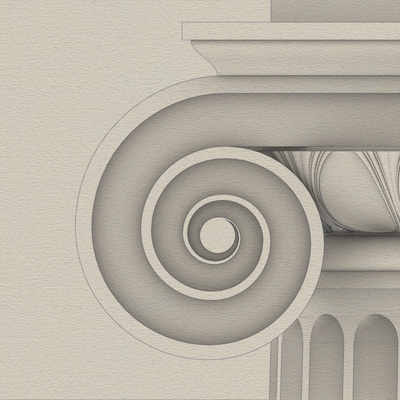
#EvolutionOfScotia
#Scotia is a new concave #molding that we are seeing for the first time in the #IonicOrder. Its #primaryProfileCurve is a compound curve that is always segmented 1/3 and 2/3 from top to bottom. The two segments have different radii, but they also have a common tangent where they meet.
The scotia molding went through some evolutionary stages as shown in the sketch.
In the classic #Vignola version, the scotia used in the column base is smaller and gouges out a portion of the bottom fillet. Vignola did that to accentuate the effect of incident light and bring out the shadows. He must have really liked the #lightAndShade effect because he had TWO of them in the classic column base for the #IonicColumn.
An intermediary variant then emerged in which the larger arc was tangential to the bottom fillet instead of gouging it out. It still allowed for the interplay of light and shade as it had a lip that extended above the nominal fillet. Also, it was 4/3 the size of the Vignola variant and the fillets were twice as tall, ostensibly to make the lip more conspicuous, and provide some utility or justification for the lip.
If you are into #font design or you are an avid calligrapher, you will never look at font #serifs the same way after looking at the intermediate evolutionary stage of the scotia. In particular, the #Optima font is classified as #sansSerif, but the stem in its repertoire of characters has an uncanny resemblance at the tip of the lip.
Unfortunately, the lip didn't seem durable as it was prone to chipping. While Optima still thrives, designers rejected the lip of the scotia as vestigial over time, and used an ellipse for the larger arc so that it was tangential to the fillet right where the fillet ended. This design has endured, and the variant of the column base that uses this molding is called either the "modern" base or the #AtticBase. The etymology is from Latin #Atticus which means ‘relating to #Athens or #Attica region of #Greece.'

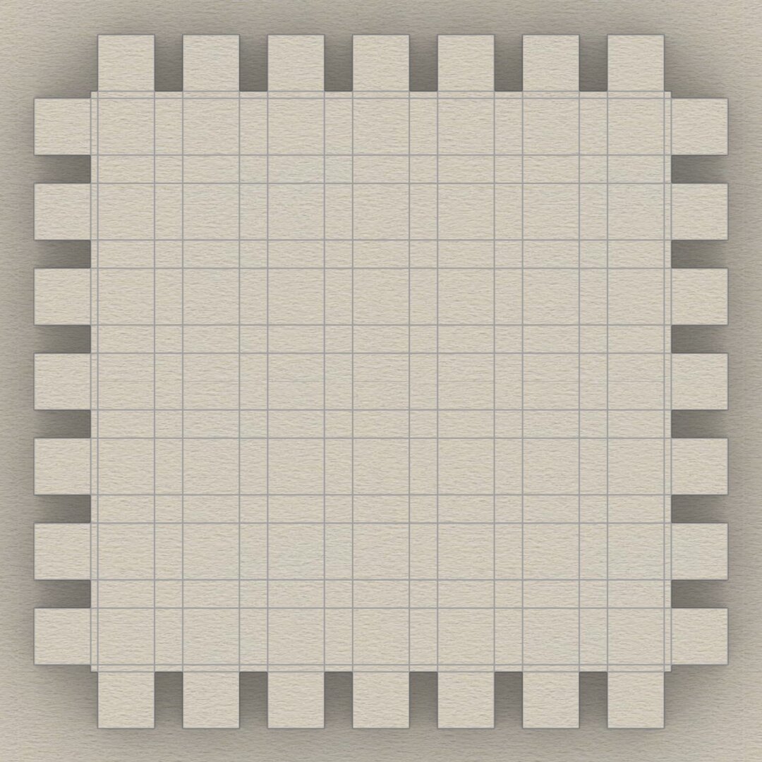
This sketch shows the arrangement of #dentils in the classic variation of the #IonicEntablature. It shows the full layout, but most of the top is obscured by the top portion of the #cornice. Only the outside square shapes are actually visible.
Each #dentil has a square "footprint" that is 4 parts by 4 parts (32*32 units) and is 6 parts (48 units) tall. The spacing between each dentil is 2 parts (16 units).
Dentils project 4 parts (or 32 units) from the face of the #fascia on which they rest.
Each face of the fascia has 7 dentils with the middle dentil laterally centered and directly in front of the column axis. The 2 side dentils are on side faces, and that is apparent in the darker shading in the sketch at https://pixelfed.social/i/web/post/790782316675150160. Take the time to reconcile this with the numbers listed in #Scarlata's #PracticalArchitecture.
The 3D reconstruction from the #primaryProfileCurves is very similar to that of the #IonicPedestal, with #extrusion, #mitering, #joining, and #capping planar holes as described in https://pixelfed.social/i/web/post/790645054230337543 — just set the dentils aside, for now.
Once you have capped the #planarHoles to get a solid, analyze the edges of the solid in the #CAD program for #nakedEdges and #nonManifoldEdges.
Then, extrude the dentils outline (in the top view) to a height of 48 units (in the front view).
Now perform a #booleanUnion of the two solid shapes to get the complete #entablature.
Finally, check the edges of the solid in the #CAD program AGAIN for #nakedEdges and #nonManifoldEdges.
With this, we have finished two of the three main components of the #IonicOrder. There's a modern version of the Ionic entablature with #modillions, which I will describe later.
Next, we move on to the biggest, most conspicuous part of the order — the #IonicColumn.
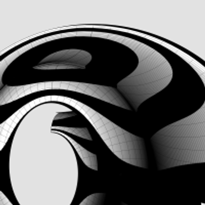
This is a sketch of the top of an #IonicColumn with #scrolls, #volutes, and other embellishments. Before I delve into my modern designs, I want to emphasize that most of them are rooted in classical designs of antiquity but still retain their timeless essence.
Different regions of the world have developed and refined distinct design patterns over thousands of years. Greeks, Romans, Ottomans, Arabs, Moghuls, Hindus, and others — all have something to contribute to what we call #art and #design in human civilization.
My initial focus is on Greco-Roman architecture and design which has five distinct orders: #Tuscan, #Doric, #Ionic, #Corinthian, and #Composite. Of these, the #IonicOrder is of medium complexity. The Doric and Tuscan are simpler, while Corinthian and Composite are more complex.
Because of its moderate complexity, I chose the Ionic Order for a complete and systematic look at its design methodology and proportions of its elements. I use concrete measurements to make concepts easier to understand. Once you understand the Ionic order, it's easy to step down to the Doric and Tuscan orders. It's more work to step up to the Corinthian and Composite orders, but if you follow my methodology with dedication, you will learn the skills necessary to tackle the more complex orders or branch out on your own.
In an earlier post, I mentioned the importance of sticking to proportions and measurements. I'll point out opportunities for variation as we progress systematically.
An additional, but very important point I want to emphasize is that this #digitalArt is not just #art, but #engineering design as well, because the end result is to realize physical artifacts from these designs, whether by #AdditiveManufacturing (#3DPrinting), #SubtractiveManufacturing (#CNC #Carving), #ReliefEngraving, #Printing, or any other physical realization.
You'll need a #CAD tool to practice, but you can also follow along as a reader initially, and come back when you're ready to practice
⬆️ #ClassicalArchitecture #3DModeling
>> The heights of #Tuscan, #Doric, #Ionic, and #Composite columns are in the ratio 7:8:9:10 for the same column diameter See ➡️ https://graphics.social/@Alankar/113742694767353418
Using µ = 288 as the basis, the height of the #IonicColumn would be 288 * 9 = 2592 units.
>> The pedestal, column, and entablature are always in 4:12:3 ratio (🧵 above).
So pedestal height would be 1/3 of 2592 = 864 units. Entablature would be 1/4 of 2592 = 648 units.
Total = 864 + 2592 + 648 = 4104 units
Client Info
Server: https://mastodon.social
Version: 2025.07
Repository: https://github.com/cyevgeniy/lmst