Sixers’ NBA Draft 2025: VJ Edgecombe ticks all the boxes to be The Guy at No. 3 https://www.rawchili.com/nba/118738/ #76ers #76ersAnalysis #76ersDraftRumorsNews #all #at #ballers #Basketball #be #boxes #draft #Edgecombe #FrontPage #guy #liberty #NBA #NBADraft #no #Philadelphia #Philadelphia76ers #Philadelphia76ers #reviewed #sixers #the #ticks #To #vj
#Ticks

I wasn't planning on taking any walks in the woods this week with the heatwave anyway, but I am glad to know this Tick Index from Fordham exists.
Atari 2600 Controller Shield PCB Revisited – Part 3
Following on from Atari 2600 Controller Shield PCB Revisited – Part 2 someone on Mastodon made the point that the reason they tended to use RC circuits to read paddles “back in the day” was due to the expense of ADCs.
Which triggered a bit of an “oh yeah” moment.
The whole point was not to worry about the analog levels at all, and just measure the time it takes for the pin to read HIGH again.
So this looks back at removing the whole ADC thing with a simple “if (digitalRead(pin))” condition!
Warning! I strongly recommend using old or second hand equipment for your experiments. I am not responsible for any damage to expensive instruments!
If you are new to Arduino, see the Getting Started pages.
The Code
The overarching principles are the same as for Atari 2600 Controller Shield PCB Revisited – Part 2 but instead of all the bespoke code to read the analog to digital converter, I’m relying on the following:
- A digital input pin has a threshold for which the input is considered HIGH.
- We can wait for the input reading to register as HIGH instead of looking for absolute thresholds of an analog value.
- For an ATMega328P the threshold is 0.6 x VCC or around 3V. This is equivalent to just over 610 on a 0 to 1023 scale of an equivalent analog reading.
Taking this into account and using largely the same ideas as before, I can reuse most of the code but with the following timing and threshold values instead:
- Start scaling (the 0 point): 10
- End scaling (the 1023 point): 350
The timer TICK is still 100uS and the “breakout” point is still 1000.
When it comes to reading the digital INPUT, I’m using PORT IO once again for speed and expediency.
for (int i=0; i<4; i++) {
  if ((PINC & (1<<i)) == 0) {
    // Still not HIGH yet
  }
}
Here is the complete, now greatly simplified, basic code:
#include <TimerOne.h>

#define RAW_START    10
#define RAW_END     350
#define RAW_BREAK  1000
#define RAW_TICK    100

unsigned padState;
unsigned padCount[4];
unsigned atariValue[4];

void atariAnalogSetup() {
  Timer1.initialize(RAW_TICK);
  Timer1.attachInterrupt(atariAnalogScan);
  padState = 0;
}

void atariAnalogScan (void) {
  if (padState == 0) {
    DDRC  = DDRC | 0x0F;     // A0-A3 set to OUTPUT
    PORTC = PORTC & ~(0x0F); // A0-A3 set to LOW (0)
    padState++;
  } else if (padState == 1) {
    DDRC  = DDRC & ~(0x0F);  // A0-A3 set to INPUT
    for (int i=0; i<4; i++) {
      padCount[i] = 0;
    }
    padState++;
  } else if (padState > RAW_BREAK) {
    for (int i=0; i<4; i++) {
      atariValue[i] = 1023 - map(constrain(padCount[i],RAW_START,RAW_END),RAW_START,RAW_END,0,1023);
    }
    padState = 0;
  } else {
    for (int i=0; i<4; i++) {
      if ((PINC & (1<<i)) == 0) {
        padCount[i]++;
      }
    }
    padState++;
  }
}

int atariAnalogRead (int pin) {
  return atariValue[pin-A0];
}

void setup() {
  Serial.begin(9600);
  atariAnalogSetup();
}

void loop() {
  Serial.print(padState);
  Serial.print("\t[ ");
  for (int i=0; i<4; i++) {
    Serial.print(atariAnalogRead(A0+i));
    Serial.print("\t");
    Serial.print(padCount[i]);
    Serial.print("\t][ ");
  }
  Serial.print("\n");
}
Closing Thoughts
Sometimes one really can’t see the “wood for the trees” and this was one of those occasions. I was so took up with thinking about how a modern system might think about a problem without thinking about the original reason for the particular solution.
It makes so much more sense thinking about it in these terms now. All it took was an observation from another, namely:
“So I know the RC timer is the classic way to sense analog paddles but they also didn’t have cheap ADCs back then.”
Many thanks “Chip” for that observation 🙂
Kevin
#arduinoUno #atari #atari2600 #include #potentiometer #TICKs
https://www.fogolf.com/991290/lpga-winner-in-spotlight-after-absurd-tick-bites-from-erin-hills/ LPGA Winner in Spotlight After Absurd Tick Bites From Erin Hills #ErinHills #Golf #GolfNews #KpmgWomen'sPgaChampionship #LPGA #Ticks

404 Media: AI Scraping Bots Are Breaking Open Libraries, Archives, and Museums. “AI bots that scrape the internet for training data are hammering the servers of libraries, archives, museums, and galleries, and are in some cases knocking their collections offline, according to a new survey published today.” As you might imagine this drives me absolutely WILD.
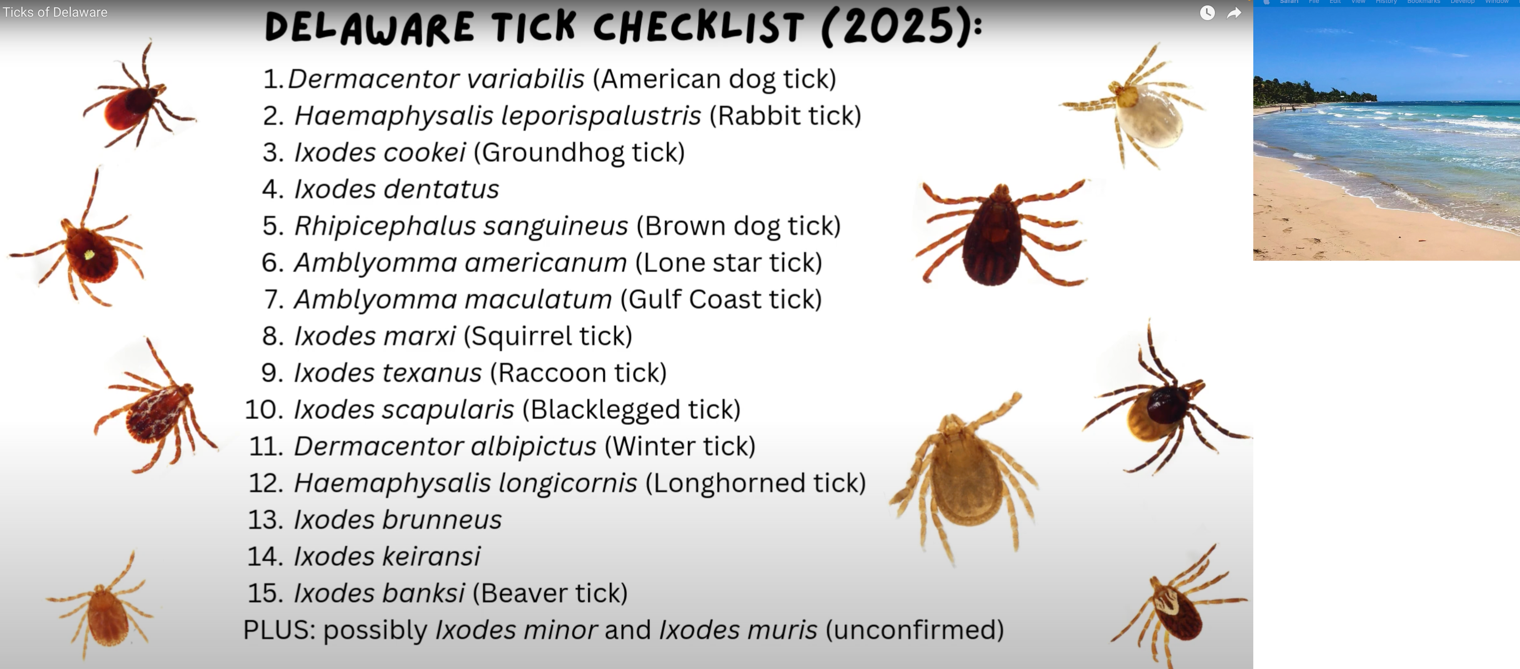
Updated checklist of tick species currently known to occur in Delaware
Report on a total of 15 established hard tick species (Ixodidae), as well as additional Ixodidae and 2 soft tick species (Argasidae) that are not yet confirmed as established.
Report summarizes the phenology of each species and its known distribution in Delaware and public health importance, with a table of known tick-host associations for Delaware.
#ticks #lyme #lonestartick #deertick #delaware
https://academic.oup.com/jme/advance-article/doi/10.1093/jme/tjaf029/8108234
https://academic.oup.com/jme/advance-article/doi/10.1093/jme/tjaf029/8108234
Calling all citizen scientists in SD to stomp out tick-borne diseases
#KXLGNews #KXLGRadio991 #GreaterDakotaNewsService #SouthDakota #news #ticks
Whoa, be mindful of the increase of Lyme disease in Michigan.
State health officials warn of 168% increase in past 5 years in tick-borne illness in Michigan.
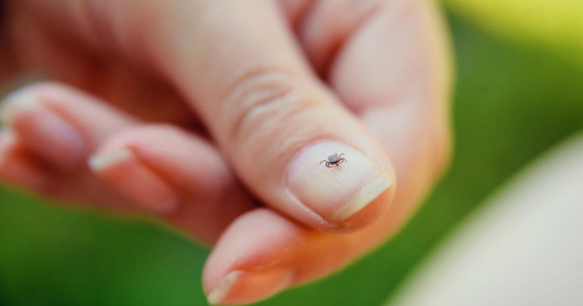
Also, PSA: It's #TickSeason 🤢
Pulled two from my leg, and saw a couple crawling on #LadyDuchess (she's on preventive, they weren't biting her)
- Make sure you and your #Dogs take precautions
- Thoroughly inspect after #Hiking
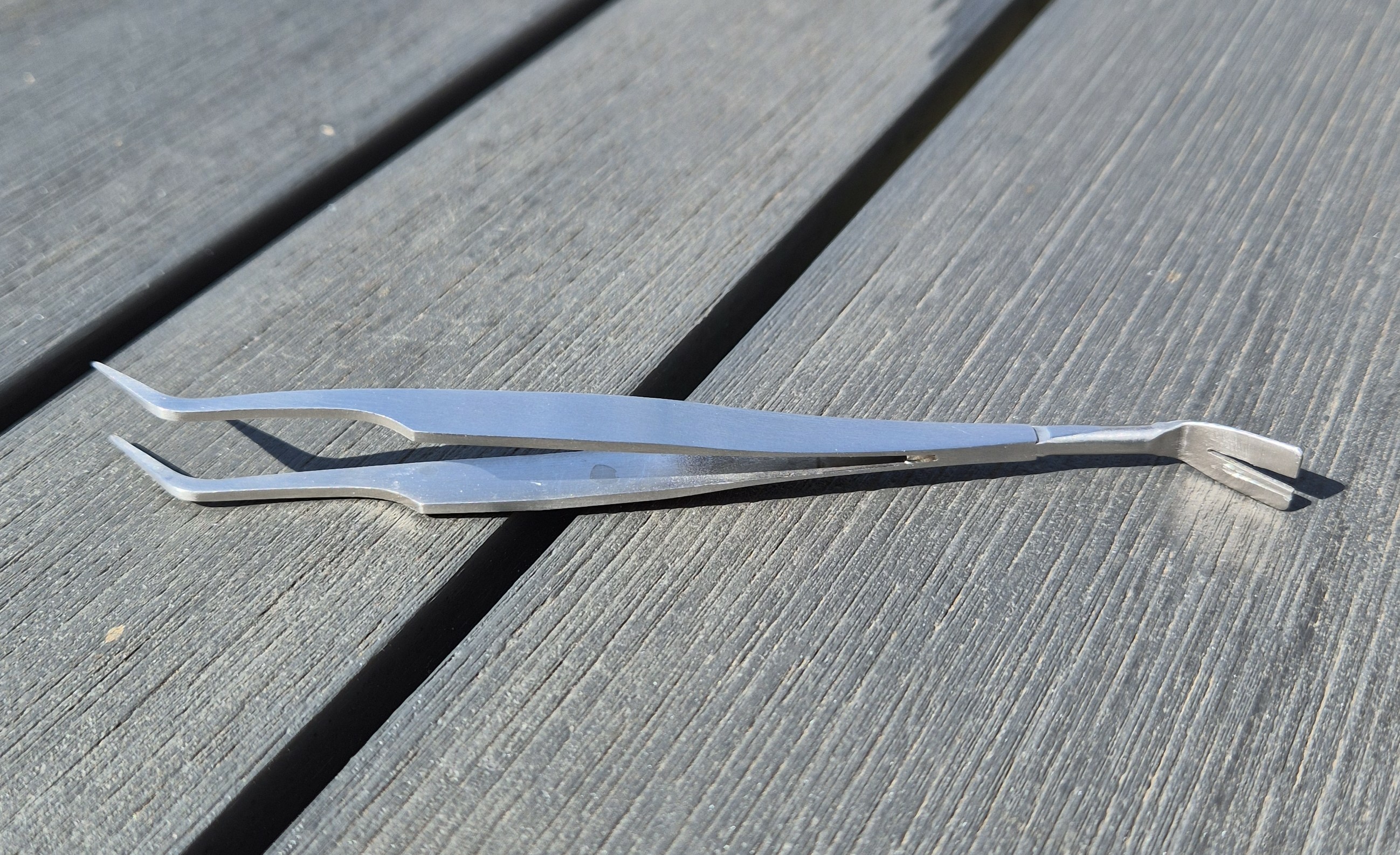
- Use tweezers - suffocation/burning are NOT recommended methods of removal
---
CDC has great into about where #Ticks can be found, why they are a danger, preventing tick-borne diseases, and what to do if you're bitten.
Since we are right in Tick season, I penned my two cents about them, not much or scientifically. But hopefully it would help one person from catching the horrific Lyme. Be careful out there.
https://woollypigs.com/ticked_off
#TrailRunning #Outdoors #Hiking #Trekking #Running #RunnersOfMastodon #RunningWithDogs #Lyme #Ticks
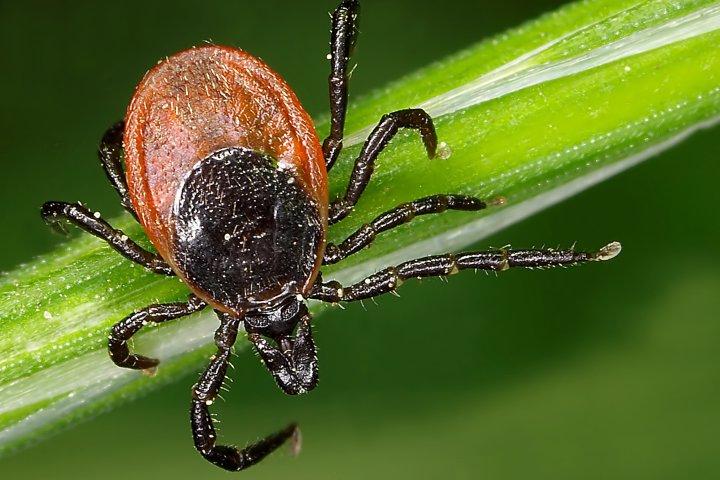
Tick season is back. How to stay safe around these risky bloodsuckers
Thanks to warming winters and milder temperatures, ticks are thriving in more parts of the country than ever before — bringing the risk of tick-borne illnesses like Lyme disease.
#health #weather #safety #Canada #Environment #Ticks
https://globalnews.ca/news/11172526/tick-season-canada-how-to-stay-safe/

Das wichtigste Werkzeug für den #Hund ist im Moment die Pinzette zum Entfernen von #Zecken!
The most important tool for the #dog right now are the tweezers for removing #ticks!
Tick season is back. How to stay safe around these risky bloodsuckers
Thanks to warming winters and milder temperatures, ticks are thriving in more parts of the country than ever before — bringing the risk of tick-borne illnesses like Lyme disease.
#health #weather #safety #Canada #Environment #Ticks
https://globalnews.ca/news/11172526/tick-season-canada-how-to-stay-safe/

If #GustavTheCat looks a little tired, it's probably from carrying around 10+ #ticks we removed from him this morning. I wonder where he's hanging out at night.

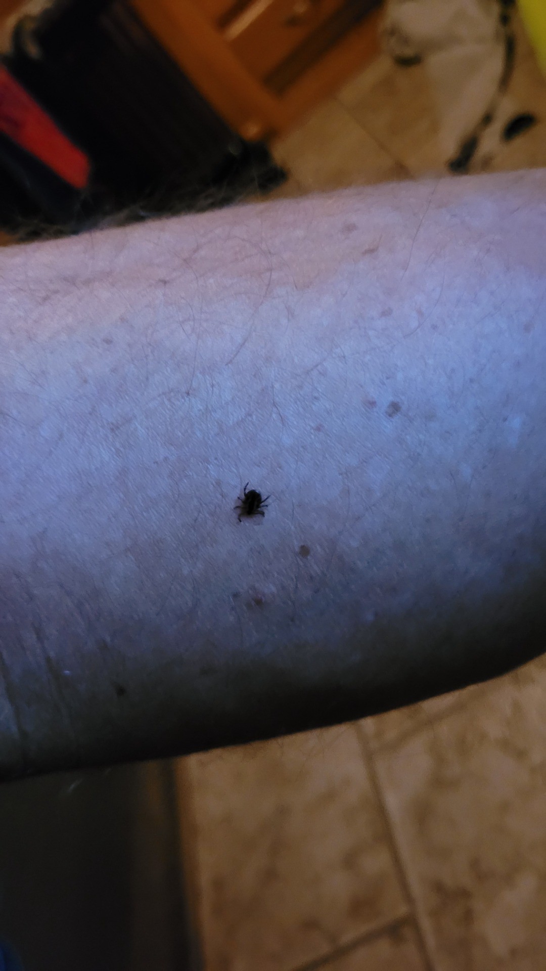
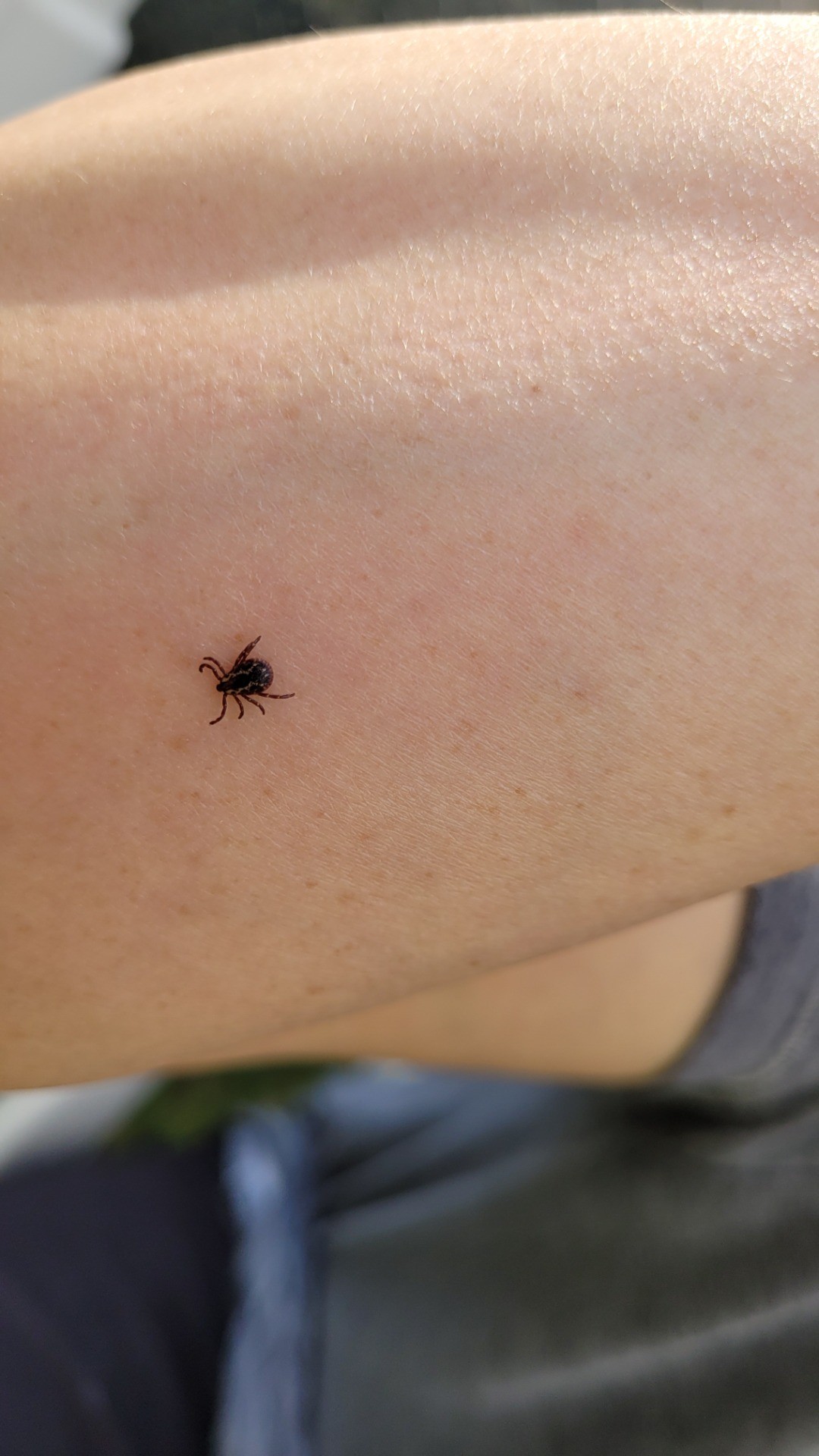
da Good, da Bad & da Ugly...
In this case:
Da horrific - #Ticks , last week Farmbouy Sr., and last night Farmbouy got 1. Yep it b full body search before and fater bedtime, from now till freeze'n temps b back!
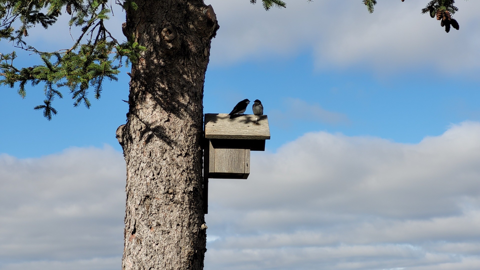
Da - Ahhh,💞 a couple of swallows make'n a home in da Simple Simon Birdhouse.
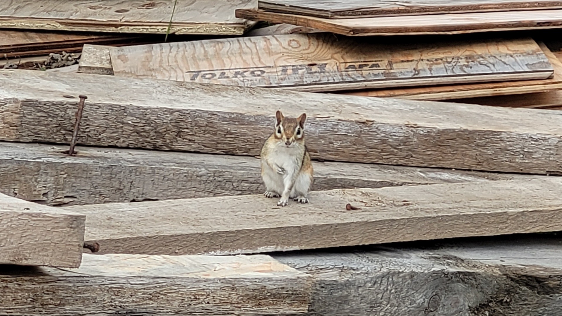
DA #Kawaii Chippie b da official Kawaii Kritter of Kanada🥰
PS Hamilton region sux 4 ticks, butt here is a great Info page.
Client Info
Server: https://mastodon.social
Version: 2025.04
Repository: https://github.com/cyevgeniy/lmst