ATtiny85 MIDI to CV
There are a number of projects out there that provide a MIDI to CV function utilising some flavour of the ATtiny family of microcontrollers. But most of them go from USB MIDI to CV but I wanted a genuine 5-pin DIN MIDI to CV. This was the result.
It has taken a basic MIDI in circuit from the Internet (Google will find a few of these kicking around) and pairs it with the ATtiny85 CV out section of Jan Ostman’s cheap USB MIDI 2 CV design (Jan Ostman’s site is no more so I can’t link to it anymore).
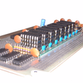
The result is as follows.
Update 2025: if you’d like to have this in a module you can just buy and use, take a look at https://lectronz.com/products/midi-to-cv. Note: I don’t have this, and have no connection with it, I’m just passing this on as I saw it was essentially the same circuit and thought it might be useful!
Update July 2021: Added a TRIGGER output on Pin 5.
I also have a version for the ATtiny2313, but the main changes are as you’d expect. Basically I was having problems with the ATtiny85 missing MIDI messages and wondered if a hardware UART would be better. Turned out it was just my dodgy code with no real error checking getting out of sync with the MIDI stream. But it took trying it on a 2313 to highlight the real issue, so back to the ATtiny85 and now all is well.
Design wise, its fairly simple ATtiny85 wise with the pin usage as follows:
- SoftwareSerial receive on D3 (PB3) which is physical pin 2.
- Gate output on D2 (PB2) which is physical pin 7.
- CV output using the PWM signal tied to OC1A triggered off timer 1, which is D1 (PB1) on physical pin 6.
- Update July 21: Trigger output on D0 (PB0) which is physical pin 5.
The code uses the same trick that Jan Ostman used in his code – if the top compare value for PWM operation is 239 then there are 240 graduations for PWM. To cover a MIDI range of C2 (note 36) to C7 (note 96) is 60, so the PWM compare value required for a linear CV voltage output is basically (note-36)*4.
In terms of timer control registers, this all translates over to (refer to the ATtiny85 data sheet):
- Set PWM1A i.e. PWM based on OCR1A
- Set COM1A1 i.e. Clear OC1A (PB1) output line
- Set CS10 i.e. Prescaler = PCK/CK i.e. run at Clock speed
- Clear PWM1B is not enabled (GTCCR = 0)
The value for the PWM cycle is set in OCR1C to 239, and the compare value is set in OCR1A between 0 and 239, thus representing a range of 0 to 5v giving 1v per octave, assuming a 5v power supply.
When porting to the ATtiny2313, a similar scheme was used, but timer 1 is a 16 bit timer, and the control registers were slightly different, but I still used the 0-239 range.
Reading around the different modes, I ended opting for the use of Fast PWM with the compare value in OCR1A and the maximum PWM cycle value (239) in ICR1. The timer register settings were thus as follows:
Timer 1 Control Register A (TCCR1A):
- 7 COM1A1 = 1 COM1A1(1); COM1A0(0) = Clear OC1A on compare match; set at TOP
- 6 COM1A0 = 0
- 5 COM1B1 = 0
- 4 COM1B0 = 0
- 3 Resv = 0
- 2 Resv = 0
- 1 WGM11 = 1 WGM11(1); WGM10(0) = PWM from OCR1A based on TOP=ICR1
- 0 WGM10 = 0
Timer 1 Control register B (TCCR1B):
- 7 ICNC1 = 0
- 6 ICES1 = 0
- 5 Resv = 0
- 4 WGM13 = 1 WGM13(1); WGM12(1) = PWM from OCR1A based on TOP=ICR1
- 3 WGM12 = 1
- 2 CS12 = 0 CS12(0); CS11(0); CS10(1) = Prescaler = PCK/CK i.e. run at Clock speed
- 1 CS11 = 0
- 0 CS10 = 1
Timer 1 Control Register C left all zeros.
I don’t know if it was the version of the ATtinyCore I was using, but the bit and register definitions for Timer1 for the ATtiny2313 didn’t seem to match the datasheet, so I just used the bit codes directly.
In terms of ATtiny2313 pin definitions, the following were used:
- Hardware serial receive on D0 (PD0) which is physical pin 2.
- Gate output on D11 (PB2) which is physical pin 14.
- CV output using the PWM signal tied to OC1A triggered off timer 1, which is D12 (PB3) on physical pin 15.
A quick note on the MIDI serial handling. My first code was very lazy and basically said:
Loop: IF (serial data received) THEN read MIDI command value IF (MIDI note on received) THEN read MIDI note value read MIDI velocity value set CV out value based on MIDI note value set Gate signal HIGH ELSE IF (MIDI note off received) THEN read MIDI note value read MIDI velocity value set CV out value based on MIDI note value set Gate signal LOW ELSE ignore and go round again waiting for serial data ENDIF ENDIFEND Loop
This generated a very quirky set of issues. Basically when there was serial data available and a MIDI note on or off command detected, the read of the note and velocity data was returning and error (-1) which I never bothered checking. Basically the code was running too fast and the next MIDI byte hadn’t registered yet. So when (-1) was passed on as the MIDI note, it was resulting in a note on code thinking the MIDI note was 255, which was rounded up to the highest note (96).
The result was that I could see the gate pulsing in response to MIDI note on and off messages, but the CV voltage went high as soon as the first MIDI message was received.
The next version used a test that said
IF (at least three bytes of serial data received) THEN
which means that if things get out of sync, eventually bytes are skipped until there are three bytes that equate to a note on/off message. Crude, but it worked enough to show the principle.
The final code includes proper handling of the “Running Status” of MIDI, as described here: http://midi.teragonaudio.com/tech/midispec/run.htm
November 2020 Update:
I’ve moved the channel handling into the command checking – the code was getting confused in a multi-channel data stream as the channel handling was performed too early and not reset properly.
June 2021 Update:
I’ve fixed a couple of issues with the Note Off handling. Essentially it wasn’t checking that the Note Off event corresponded to the currently playing note, so if you had overlapping notes, the CV would change, but the Note Off from the first note playing would then stop the second note playing too.
July 2021 Update:
Added a TRIGGER output on pin 5. Note that this is really at my limit of being able to test, so consider it experimental, but please do let me know how you get on and be sure to report back if there are any issues!
There are now four functions that determine how the GATE and TRIGGER work – gateOn, gateOff, triggerOn, triggerOff. By default these use HIGH for “on” and LOW for “off” but that is now easily changed in these functions if you need (for example) a negative TRIGGER or somesuch. They are both 5V signals largely straight out of the ATtiny85’s IO pins.
The width of the TRIGGER pulse itself is set at the top of the file to 1000 micro-seconds (i.e. 1 millisecond). You can change this to whatever you like, but I’m not sure what would happen if you try to go much shorted than a mS, but see how you go. Ultimately it is limited by the time it takes the ATtiny85 to run the loop() and the resolution of the micros() function.
I used the 8MHz internal clock for the ATtiny85 so be sure to “set the fuses” (i.e. use the “program bootloader” option) to this effect.
To test all of it together, I used my ATtiny85 MIDI Tester.
I might add some kind of selection for the MIDI channel. Right now its hard-coded in a #define. One option might be using an analogue input and a multi-position switch with a resistor network. Or maybe a “tap to increase the channel” digital input switch. Or if I use the 2313 version, I could use more pins and use a BCD or hex rotary switch or DIP switches.
Here is the full code for the ATtiny85 version, which can be loaded up from the Arduino environment using the ATtiny85 core by Spence Konde.
// MIDI to CV using ATTiny85// NB: Use Sparkfun USB ATTiny85 Programmer// Set Arduino env to USBTinyISP (Slow)// Set to 8MHz Internal Clock (required for MIDI baud)//// Update: Nov 2020 - fixed channel handling// Update: Jun 2021 - fixed NoteOff/gate handling// Update: Jul 2021 - added trigger output//#include <SoftwareSerial.h>//#define CVOUTTEST 1//#define MIDITEST 1#define MIDIRX 3 // 3=PB3/D3 in Arduino terms = Pin 2 for ATTiny85#define MIDITX 4 // 4=PB4/D4 in Arduino terms = Pin 3 for ATTiny85#define MIDICH 1 // Set this to the MIDI channel to listen to (1 to 16)#define MIDILONOTE 36#define MIDIHINOTE 96// Output:// PB2 (Ardiuno D2) = Pin 7 = Gate Output// PB1 (Arduino D1) = Pin 6 = Pitch CV Output// PB0 (Arduino D0) = Pin 5 = Trigger Output//// PB1 used as PWM output for Timer 1 compare OC1A#define GATE 2 // PB2 (Pin 7) Gate#define PITCHCV 1 // PB1 (Pin 6) Pitch CV#define TRIGGER 0 // PB0 (Pin 5) Trigger#define TRIGPULSE 1000 // Width of the trigger pulse (uS)SoftwareSerial midiSerial(MIDIRX, MIDITX);byte noteplaying;uint32_t pulsemicros;void setup() { // put your setup code here, to run once: midiSerial.begin (31250); // MIDI Baud rate pinMode (GATE, OUTPUT); pinMode (PITCHCV, OUTPUT); pinMode (TRIGGER, OUTPUT); // Use Timer 1 for PWM output based on Compare Register A // However, set max compare value to 239 in Compare Register C // This means that output continually swings between 0 and 239 // MIDI note ranges accepted are as follows: // Lowest note = 36 (C2) // Highest note = 96 (C7) // So there are 60 notes that can be received, thus making each // PWM compare value 240/60 i.e. steps of 4. // // So, for each note received, PWM Compare value = (note-36)*4. // // Timer 1 Control Register: // PWM1A = PWM based on OCR1A // COM1A1 = Clear OC1A (PB1) output line // CS10 = Prescaler = PCK/CK i.e. run at Clock speed // PWM1B is not enabled (GTCCR = 0) // TCCR1 = _BV(PWM1A)|_BV(COM1A1)|_BV(CS10); GTCCR = 0; OCR1C = 239; OCR1A = 0; // Initial Pitch CV = 0 (equivalent to note C2) gateOff(); triggerOff();}void setTimerPWM (uint16_t value) { OCR1A = value;}void gateOn() { digitalWrite (GATE, HIGH);}void gateOff() { digitalWrite (GATE, LOW); }void triggerOn() { digitalWrite (TRIGGER, HIGH); pulsemicros = micros() + TRIGPULSE;}void triggerOff() { // Turn off the trigger only after a short delay if (pulsemicros < micros()) { digitalWrite (TRIGGER, LOW); }}void loop() {#ifdef CVOUTTEST for (midi_note=36; midi_note<=90; midi_note++) { midiNoteOn (midi_note, 64); delay (500); midiNoteOff (midi_note, 0); delay (500); }#else if (midiSerial.available()) { // pass any data off to the MIDI handler a byte at a time doMIDI (midiSerial.read()); }#endif triggerOff();}uint8_t MIDIRunningStatus=0;uint8_t MIDINote=0;uint8_t MIDILevel=0;void doMIDI (uint8_t midibyte) { // MIDI supports the idea of Running Status. // If the command is the same as the previous one, // then the status (command) byte doesn't need to be sent again. // // The basis for handling this can be found here: // http://midi.teragonaudio.com/tech/midispec/run.htm // // copied below: // Buffer is cleared (ie, set to 0) at power up. // Buffer stores the status when a Voice Category Status (ie, 0x80 to 0xEF) is received. // Buffer is cleared when a System Common Category Status (ie, 0xF0 to 0xF7) is received. // Nothing is done to the buffer when a RealTime Category message is received. // Any data bytes are ignored when the buffer is 0. // if ((midibyte >= 0x80) && (midibyte <= 0xEF)) { // // MIDI Voice category message // // Start handling the RunningStatus MIDIRunningStatus = midibyte; MIDINote = 0; MIDILevel = 0; } else if ((midibyte >= 0xF0) && (midibyte <= 0xF7)) { // // MIDI System Common Category message // // Reset RunningStatus MIDIRunningStatus = 0; } else if ((midibyte >= 0xF8) && (midibyte <= 0xFF)) { // // System real-time message // // Ignore these and no effect on the RunningStatus } else { // // MIDI Data // if (MIDIRunningStatus == 0) { // No record of state, so not something we can // process right now, so ignore until we've picked // up a command to process return; } // Note: Looking for the command on our channel if (MIDIRunningStatus == (0x80|(MIDICH-1))) { // First find the note if (MIDINote == 0) { MIDINote = midibyte; } else { // If we already have a note, assume its the level MIDILevel = midibyte; // Now we have a note/velocity pair, act on it midiNoteOff (MIDINote, MIDILevel); MIDINote = 0; MIDILevel = 0; } } else if (MIDIRunningStatus == (0x90|(MIDICH-1))) { if (MIDINote == 0) { MIDINote = midibyte; } else { // If we already have a note, assume its the level MIDILevel = midibyte; // Now we have a note/velocity pair, act on it if (MIDILevel == 0) { midiNoteOff (MIDINote, MIDILevel); } else { midiNoteOn (MIDINote, MIDILevel); } MIDINote = 0; MIDILevel = 0; } } else { // MIDI command we don't process or not on our channel } }}void midiNoteOn (byte midi_note, byte midi_level) { // check note in the correct range of 36 (C2) to 90 (C7) if (midi_note < MIDILONOTE) midi_note = MIDILONOTE; if (midi_note > MIDIHINOTE) midi_note = MIDIHINOTE; // Scale to range 0 to 239, with 1 note = 4 steps midi_note = midi_note - MIDILONOTE; // Set the voltage of the Pitch CV and Enable the Gate and Trigger setTimerPWM(midi_note*4); gateOn(); triggerOn(); noteplaying = midi_note;#ifdef MIDITEST // Write back ASCII (binary) midiSerial.print (midi_note+36, HEX);#endif}void midiNoteOff (byte midi_note, byte midi_level) { // check note in the correct range of 36 (C2) to 90 (C7) if (midi_note < MIDILONOTE) midi_note = MIDILONOTE; if (midi_note > MIDIHINOTE) midi_note = MIDIHINOTE; // Scale to range 0 to 239, with 1 note = 4 steps midi_note = midi_note - MIDILONOTE; // Only trigger the gate/OFF if it corresponds to the currnent note sounding if (midi_note == noteplaying) { noteplaying = 0; // Set the voltage of the Pitch CV and Disable the Gate gateOff(); // Your choice: Do you want to: // Clear the CV down to zero on NoteOff? // Set the CV to the same note as the NoteOff? // Completely leave it as it was (probably the same note as the NoteOff)?// setTimerPWM(0); // Clear to zero// setTimerPWM(midi_note*4); // Set to midi_note }#ifdef MIDITEST midiSerial.print (0xAA, HEX);#endif}#attiny2313 #attiny85 #define #else #endif #ifdef #include #midi #midi2cv