
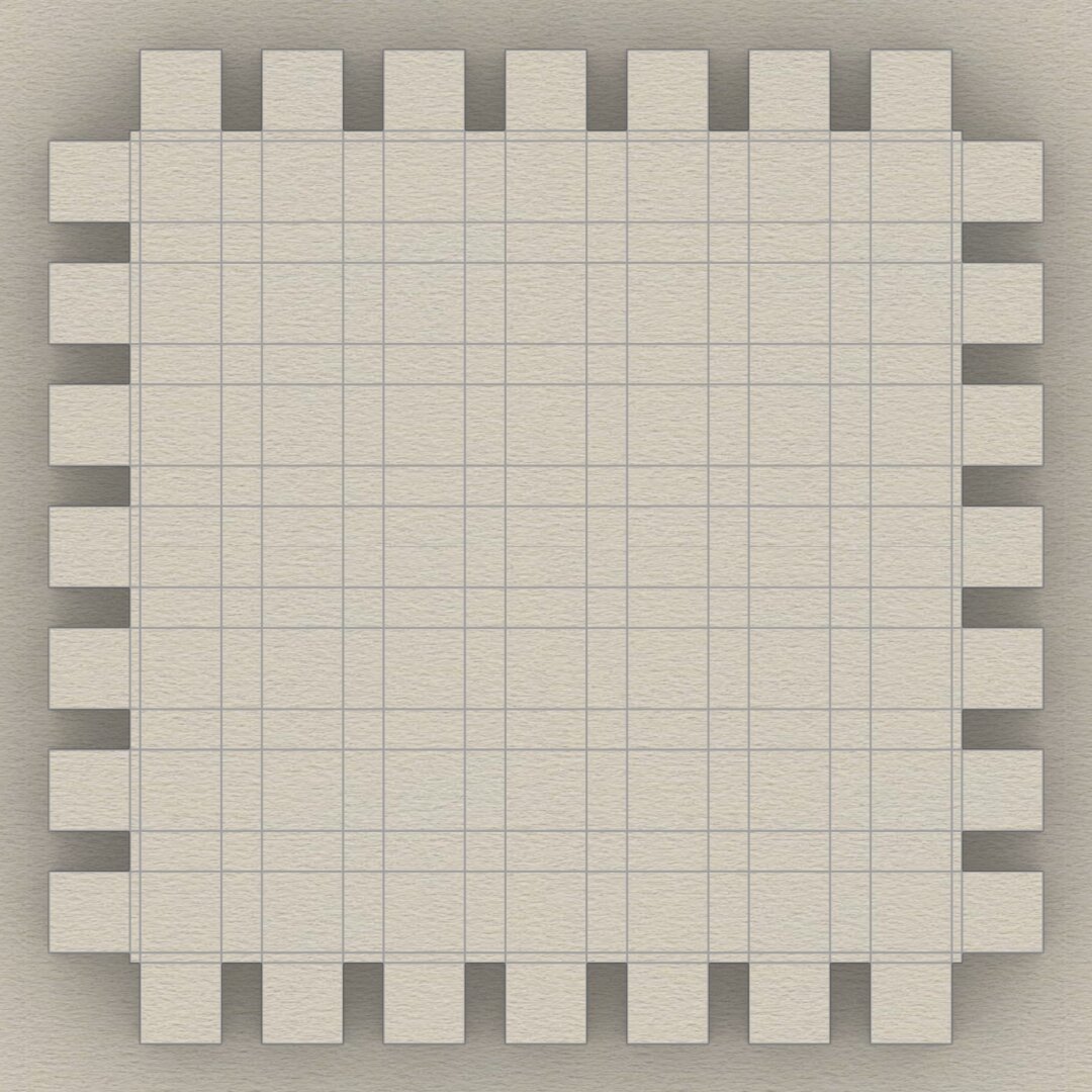
This sketch shows the arrangement of #dentils in the classic variation of the #IonicEntablature. It shows the full layout, but most of the top is obscured by the top portion of the #cornice. Only the outside square shapes are actually visible.
Each #dentil has a square "footprint" that is 4 parts by 4 parts (32*32 units) and is 6 parts (48 units) tall. The spacing between each dentil is 2 parts (16 units).
Dentils project 4 parts (or 32 units) from the face of the #fascia on which they rest.
Each face of the fascia has 7 dentils with the middle dentil laterally centered and directly in front of the column axis. The 2 side dentils are on side faces, and that is apparent in the darker shading in the sketch at https://pixelfed.social/i/web/post/790782316675150160. Take the time to reconcile this with the numbers listed in #Scarlata's #PracticalArchitecture.
The 3D reconstruction from the #primaryProfileCurves is very similar to that of the #IonicPedestal, with #extrusion, #mitering, #joining, and #capping planar holes as described in https://pixelfed.social/i/web/post/790645054230337543 — just set the dentils aside, for now.
Once you have capped the #planarHoles to get a solid, analyze the edges of the solid in the #CAD program for #nakedEdges and #nonManifoldEdges.
Then, extrude the dentils outline (in the top view) to a height of 48 units (in the front view).
Now perform a #booleanUnion of the two solid shapes to get the complete #entablature.
Finally, check the edges of the solid in the #CAD program AGAIN for #nakedEdges and #nonManifoldEdges.
With this, we have finished two of the three main components of the #IonicOrder. There's a modern version of the Ionic entablature with #modillions, which I will describe later.
Next, we move on to the biggest, most conspicuous part of the order — the #IonicColumn.
#mitering
If you've been longing for some 3D adventure, your wait is over. We have here some of the most basic 3D operations that you will use over and over.
First #join all #primaryProfileCurves into a single curve that has both straight lines and arcs. If you are unable to join them, look closely at the bottom #fillet of the #dado where it meets the top of the #reed of the #basement. There is a gap of 2 units between the fillet and the arc of the reed. Close the gap with a straight line and join the curves.
Switch from the front view to the right view, and #extrude the joined profile curves on both sides of the profile curve so that the full extrusion is a little over the total width of the pedestal. A good rule of thumb is to extrude at least 1/8th extra on both sides of the joined profile curve. This extrusion is shown in the attached image as the gray surface in perspective view.
Switch back to the front view and centered on the #columnAxis, draw a rectangle that is somewhat taller than the total pedestal height so that it extends past both the top and bottom of the pedestal extrusion from the previous step. The total width of this rectangle should be about 1.5 times the width of the pedestal. This is because we will create a cutting surface with this rectangle and rotate it 45° in the top view, and then rotate a copy of that another 90°, as shown by the flat red surfaces. The reason the width must be approximately 1.5 times (or larger) is because #Pythagoras told us that the hypotenuse of a unit square is 1.414 units. So 1.5 times should be enough.
Use the two cutting planes to cut, split, or trim the extruded surface (depending on the terminology of your CAD program). This is called #mitering. Discard the excess of the extruded surface from both ends. Also discard or hide the red mitering surfaces.
Switch to the top view and rotate the #mitered extrusion repeatedly at 90° about the column axis until you have all four sides, and join them all into an open surface.


Using the #mitering rectangle, create a flat surface on the XY plane.
Swith to the Top view and rotate the mitering surface 45° about the column axis. Make a copy and rotate it another 90° so that both mitering surfaces intersect the profile surface at 45°.
This is a perspective view of the profile extrusion surface intersected by two mitering surfaces at 45° angles.
Keep portion of the extrusion surface that is between the cutting surfaces. Trim away the rest.
Client Info
Server: https://mastodon.social
Version: 2025.07
Repository: https://github.com/cyevgeniy/lmst