#IonicVolutes are the sinews of #IonicScrolls. Without #volutes, there would be scrolls, but not #Ionic Scrolls. Each scroll starts with a volute in front and is modulated by as many as six volutes of different shapes and sizes as it reaches the back, with the scroll surface tightly hugging the volutes at each contact point in ALL 3 dimensions. This is a key point to remember before we start #reverseEngineering the first #primaryProfileCurves from old image scans.
This diagram shows the #scaffolding we will construct using straight lines and rectangles, first in 2 dimensions, then place them front-to-back in 3 dimensions using precise markers, and finally scale and superimpose the volutes on this scaffolding.
All of this will be done before we derive the primary profile curves from the image scans.
How did I know about this scaffolding? I didn't. It is not documented anywhere that I'm aware of. I developed this after years of striving to derive the correct shape, and I hope that there are people who can still "see" things I might have missed and help improve the design.
So, the actual process went like this: I drew outlines from 2D image scans in the top view, getting close to #Vignola's detailed sketches. Then, I did the same thing with image scans in the side view, and I found that the designs didn't line up.
After several iterations, I got the designs to line up in both views, and it was obvious that the bell shape of the scroll would follow the large volute in the front.
So, I used the large volute as a "rail" and tried to sweep the primary profile curves on one rail. Big mistake! The undulating shapes of the primary profile curves wobbled wildly on the single rail — The middle, 3/4, and back of the scroll were twisted out of shape!
Instead of trying to #sweepOneRail, I decided to clamp down wobbling with another operation called #sweepTwoRails, using volutes at both front and back ends as rails with less wobbling.
You will need a #CAD tool to practice.
#primaryProfileCurves

The classic #IonicScroll is the most complex of all components in the #IonicOrder mainly because it is poorly documented, if at all, and even poorly understood. It is as if the classical architects deliberately concealed its enigmatic design secrets within the confines of a smooth elegant shell that could only be revealed after intense study and analysis.
I got this impression because I spent years searching for credible and actionable documentation on how to recreate this beautiful design in a #CAD tool. In the Age of Internet and Social Media, my web searches always disappointed me because the results lacked something vital in one respect or another. Over the years, I created hundreds of versions of the scroll that looked so perfect and pleasing that I thought I had cracked it, only to find some flaw or another in my work.
So, it is with caution that I present my work on the scroll in the hopes that someone will build upon this knowledge and either validate the design, or correct it and share it with me and the rest of the world.
Looking back at my progress, I'm now surprised at how remarkably simple and elegant the design is that defied familiar geometrical construction techniques I had been using until now.
As I mentioned in my introductory post, this design can be recreated by drawing simple 2-dimensional lines and circular arcs, but instead of just #primaryProfileCurves, we will use up to three additional sets of curves — #secondaryCurves, #tertiaryCurves, and #quaternaryCurves — each derived from the previous set.
I extracted the #primaryCurves after a lengthy trial-and-error process that involved #curveFitting image scans from #Vignola’s book, #RegolaArchitettura. I had to #reverseEngineer the details because the measurements have either been lost, or are locked away in some library.
Even though we start with lines and arcs, the end results are always #NURBS curves and surfaces, but everything is done by the CAD tool, and no additional math is needed.

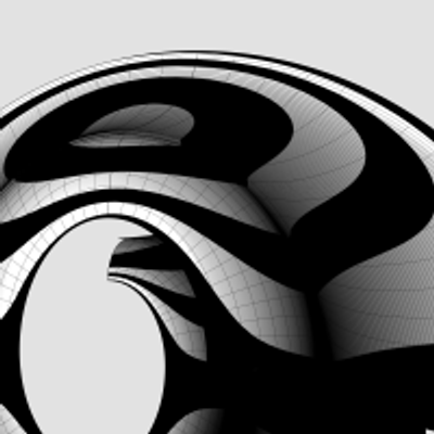
This is how a #medallion looks like when #extruded from the #primaryProfileCurves of the #IonicVolute #spirals.
These medallions are not part of the #IonicOrder and can be used as stand-alone pieces.
See https://pixelfed.social/p/Splines/792724394068855690 for how the curves are extruded.
These medallions are not part of the #IonicOrder and can be used as stand-alone pieces.
See https://pixelfed.social/p/Splines/792724394068855690 for how the curves are extruded.

We completed the #primaryProfileCurves for the classical flat #IonicVolute in https://pixelfed.social/p/Splines/792616677005177924.
To create a 3-dimensional slab with a recessed #channelGroove for the volute, you will need an outline of the volute without the inner #spiral arms.
To create the outline, make a copy of the spiral curves and work on the copy so that you don't destroy the originals. Drop a straight vertical line from the start point of outer Arc 1 of the spiral to the maxima or horizontal tangent of outer Arc 5. Trim away all other interior spiral lines and close the curve as shown in the left figure.
#Extrude the closed outline curve front to back by 1 part or 8 units in the side view. Extrude the #closedCurve of the inner and outer spirals by 2 parts or 16 units in the side view (but without the 6 unit extention on the top, which is only used when integrating the volute face with the #capital). Perform a #booleanUnion of both solids, and remember to check for #nakedEdges and #nonManifoldEdges.
The #volute design can be used outside of the #IonicColumn, such as in a #medallion. For a medallion, you have two options regarding the size of the enclosing circle.
You can either use the circle that Arc Zero lies on, or you can use the circle that Arc 1 lies on. Obviously, the latter is more compact. Just remember that the center for the larger circle is #groundZero or point 4 and the center for the smaller circle is point 1. In either case, inset the chosen circle with a concentric circle whose radius is 1 part or 8 units less.
The figure on the right shows the outlines of the enclosing circles based on the size of Arc 1 with center at Point 1.

We saw how to create the #outerSpiral for the #IonicVolute in https://pixelfed.social/p/Splines/792511464365923534 and the #innerSpiral in https://pixelfed.social/p/Splines/792561721929860260.
Create a 270° circular arc of radius 1 part (24 units at 3x scale), spanning quadrants 2, 3, and 4 as shown in orange for the #eye of the volute. The arc for the eye intersects arc 12 of both inner spiral (shown in green) and outer spiral (shown in magenta).
Outer arc 12 makes a kink where it meets the orange arc as seen in the left diagram. Discard the magenta arc 12. We can do better.
Trim both the inner arc 12 (green) and the orange arc for the eye where they meet and discard the right portions of both.
Finally, perform an #arcBlend between points A and B as shown in the right diagram. Arc blend is a new operation we are seeing for the first time. Previously we used #tangencyBlend to blend various sections of the #primaryProfileCurves for the #shaft of an #IonicColumn [https://pixelfed.social/p/Splines/791723063470910081]. Arc blend also maintains tangency, but instead of generating freeform #NURBS curves for blending, it exclusively uses one or more sections of circular arcs to blend the ends.
Join all segments of the inner spiral, outer spiral, eye, blended arcs, and straight lines near the top-left of the volute to create a single #closedCurve.
Mark the center of the eye as the origin or base point for #moving, #scaling, and other #transformations, and don't forget to scale the entire design to 1/3 using a scaling factor that has a high degree of precision, e.g., 0.33333333.
I mentioned that Dürer's approximation of a #logarithmicSpiral is close, but doesn't fit perfectly. So far there's nothing that doesn't fit. The fit issue only comes up during #scroll construction.
This concludes the task of volute construction. Next, we will look at creating the 3-dimensional volute slab using this closed volute curve and adapt it for the recessed #channelGroove in the slab.

This sketch shows the arrangement of #dentils in the classic variation of the #IonicEntablature. It shows the full layout, but most of the top is obscured by the top portion of the #cornice. Only the outside square shapes are actually visible.
Each #dentil has a square "footprint" that is 4 parts by 4 parts (32*32 units) and is 6 parts (48 units) tall. The spacing between each dentil is 2 parts (16 units).
Dentils project 4 parts (or 32 units) from the face of the #fascia on which they rest.
Each face of the fascia has 7 dentils with the middle dentil laterally centered and directly in front of the column axis. The 2 side dentils are on side faces, and that is apparent in the darker shading in the sketch at https://pixelfed.social/i/web/post/790782316675150160. Take the time to reconcile this with the numbers listed in #Scarlata's #PracticalArchitecture.
The 3D reconstruction from the #primaryProfileCurves is very similar to that of the #IonicPedestal, with #extrusion, #mitering, #joining, and #capping planar holes as described in https://pixelfed.social/i/web/post/790645054230337543 — just set the dentils aside, for now.
Once you have capped the #planarHoles to get a solid, analyze the edges of the solid in the #CAD program for #nakedEdges and #nonManifoldEdges.
Then, extrude the dentils outline (in the top view) to a height of 48 units (in the front view).
Now perform a #booleanUnion of the two solid shapes to get the complete #entablature.
Finally, check the edges of the solid in the #CAD program AGAIN for #nakedEdges and #nonManifoldEdges.
With this, we have finished two of the three main components of the #IonicOrder. There's a modern version of the Ionic entablature with #modillions, which I will describe later.
Next, we move on to the biggest, most conspicuous part of the order — the #IonicColumn.

There are two variations of the #IonicEntablature. The classic variation has #dentils, which are teeth-like structures shown here above the #frieze. The modern version has #modillions, which are projecting brackets under the #corona of the #cornice. Well, "modern" is a relative term. For designs that are more than 2000 years old, even an alteration 1000 years ago would qualify as modern.
Although the sketch shows the #entablature with a square footprint, in practice, it runs the entire length of a #colonnade (multiple columns) or an #arcade (multiple arches).
#CAD construction of the entablature is very similar to that of a #pedestal.
The first step is to consult #Vignola's #RegolaArchitettura for the visual appearance, and then consult #Scarlata's #PracticalArchitecture for #VignolaProportions in tabular form.
It is convenient to create a spreadsheet to convert the measurements given in Scarlata's book from module "parts" to your own model units based on your choice of value for the module parameter µ.
Armed with these measurements, it is time to plot the points and draw the #primaryProfileCurves on our standard 2D grid with minor grid lines 8 units apart and major grid lines 32 units apart.
In the first pass, skip the dentils and draw the profile curves for the rest of the moldings. Just as with the pedestal, I will show the macro-level plan as well as the detail plan. So, you don't have to go to Scarlata's book, but you know it's there if you want to.
I will show the dentil arrangement in a subsequent post.
Based on µ = 144, the classic Ionic entablature is 648 units (36 parts, or 4.5*µ) tall. Of this, the #architrave at the bottom is 180 units (10 parts, or 1.25*µ) tall, the frieze in the middle is 216 units (12 parts, or 1.5*µ) tall, and the cornice at the top is 252 units (14 parts, or 1.75*µ) tall.

From https://pixelfed.social/p/Splines/790645054230337543, we now have an open surface for the #IonicPedestal. To finish this, close the #planarHoles at the top and bottom with flat caps and join everything. And just like that, we have finished 1/3 of the complete #IonicOrder with very little work.
To ensure that your finished object is amenable to #3DPrinting or #CNCMilling, always check the edges of your object after all surfaces have been joined. Do this EVERY time you join surfaces to create a closed object.
Most CAD programs will offer edge analysis tools that let you detect #nakedEdges or #nonManifoldEdges. If you have either of those, your object is not #airtight, and you will not be able to physically realize it.
This version of the pedestal uses the classic variation of #CymaRecta and #CymaReversa. If you want to remain faithful to the original, then you are done.
However, designs are rarely static and they continue to evolve. There is an opportunity for a slight refinement at the top and bottom of the pedestal without compromising the integrity of the order, but it requires the introduction of a new kind of curve — a #helix, which is a coil-shaped 3D curve.
I will discuss the #helixVariation later. For now, look closely at the #basement and notice how pronounced the turns of the cyma recta are. Instead of using elliptical arcs in the #primaryProfileCurves of the cyma recta and cyma reversa, it is possible to substitute a half-turn of a helix that has been flattened to a 2D shape. The result is a softer, more gradual profile curve that produces a very refined shape.

If you've been longing for some 3D adventure, your wait is over. We have here some of the most basic 3D operations that you will use over and over.
First #join all #primaryProfileCurves into a single curve that has both straight lines and arcs. If you are unable to join them, look closely at the bottom #fillet of the #dado where it meets the top of the #reed of the #basement. There is a gap of 2 units between the fillet and the arc of the reed. Close the gap with a straight line and join the curves.
Switch from the front view to the right view, and #extrude the joined profile curves on both sides of the profile curve so that the full extrusion is a little over the total width of the pedestal. A good rule of thumb is to extrude at least 1/8th extra on both sides of the joined profile curve. This extrusion is shown in the attached image as the gray surface in perspective view.
Switch back to the front view and centered on the #columnAxis, draw a rectangle that is somewhat taller than the total pedestal height so that it extends past both the top and bottom of the pedestal extrusion from the previous step. The total width of this rectangle should be about 1.5 times the width of the pedestal. This is because we will create a cutting surface with this rectangle and rotate it 45° in the top view, and then rotate a copy of that another 90°, as shown by the flat red surfaces. The reason the width must be approximately 1.5 times (or larger) is because #Pythagoras told us that the hypotenuse of a unit square is 1.414 units. So 1.5 times should be enough.
Use the two cutting planes to cut, split, or trim the extruded surface (depending on the terminology of your CAD program). This is called #mitering. Discard the excess of the extruded surface from both ends. Also discard or hide the red mitering surfaces.
Switch to the top view and rotate the #mitered extrusion repeatedly at 90° about the column axis until you have all four sides, and join them all into an open surface.

This shows the detailed measurements of the top and bottom portions of the #IonicPedestal. For macro-level measurements, see https://pixelfed.social/p/Splines/790571135473463588
Each of the blue curve segments (lines and arcs) that are marked with a yellow bubble is the #profileCurve for a #molding whose name is inside the bubble.
Starting at the bottom, we have a #plinth, a #fillet, a #cymaRecta, and a #reed as part of the #basement of an Ionic pedestal.
Next up, we have a #fillet and a #cavetto at the bottom of the #dado, and another cavetto and fillet at the top of the dado.
Moving higher up, a reed, an #ovolo, a #corona, a #cymaReversa, and a final fillet top off the cap of the pedestal.
They are called profile curves because each is the outline or silhouette of a 3D molding as seen from one side or in a cross section. In the case of a pedestal, these curves can be used directly to recreate the 3D shape of the pedestal. For this reason and in this case, I call them #primaryProfileCurves.
This is not always the case. For more complex shapes, such as the #scroll surface of an #IonicCapital shown in https://pixelfed.social/p/Splines/789956327130679640, the profile curves recovered by #reverseEngineering the image scans in #Vignola's book cannot be used directly to sweep the scroll surface because the scroll shape is not cylindrical. Like the inside of a rose, the scroll surface follows the outlines of spiral #volutes in the front and back, neither of which are circular. So, additional steps are necessary to derive the curves that we can actually use to reconstruct the surface.
In the case of the scroll surface, the derivation of these curves is not trivial and not obvious, but it is not difficult to understand, and no math is involved. There are multiple sets of curves, and each successive set is derived from a previous set. I call them secondary, tertiary, and quaternary curves.
For now, we stick with the primary profile curves for the pedestal.

Client Info
Server: https://mastodon.social
Version: 2025.07
Repository: https://github.com/cyevgeniy/lmst