
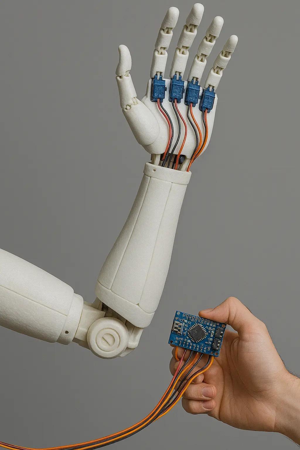
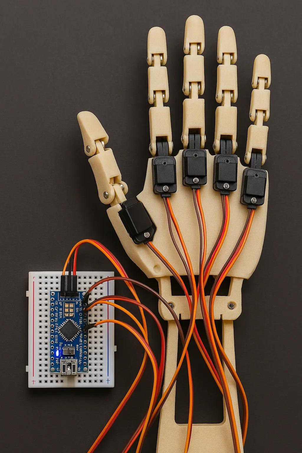
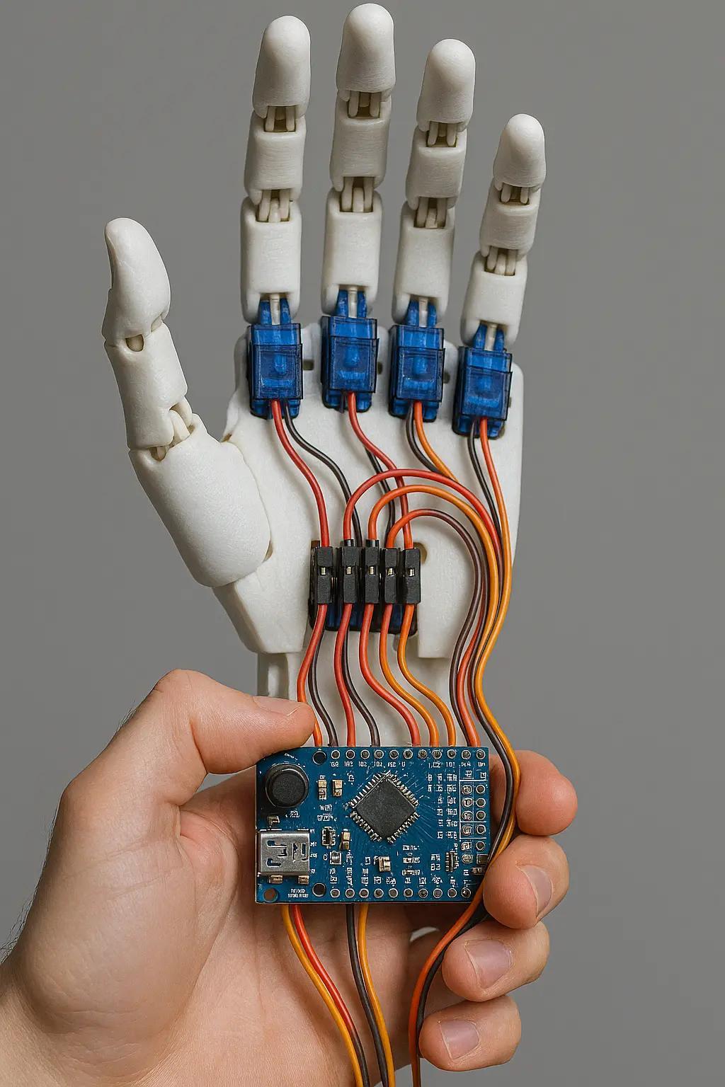
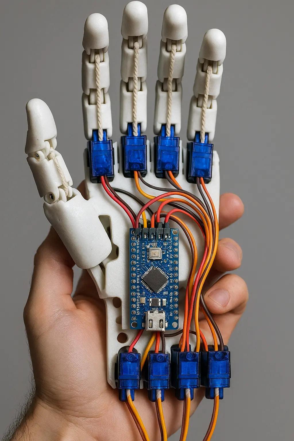
Build your own electric robot arm with Arduino Nano – explained step by step
https://ebokify.com/community/space/arduino/post/build-your-own-electric-robot-arm-with-a
#robotarm

Handmade jackets. Custom shoes. A robot arm that moves.
Tekko 2025 delivered next-level cosplay craftsmanship.
🎭 See more: www.AwesomeCast.com
#Tekko2025 #Cosplay #Craftsmanship #AwesomeCast #AnimeConvention #FanMade #RobotArm #CreativeTech


Robot Arm Gives Kids the Roller Coaster Ride of their Lives https://hackaday.com/2024/08/10/robot-arm-gives-kids-the-roller-coaster-ride-of-their-lives/ #motionsimulator #rollercoaster #RobotsHacks #robotarm #gaming #KUKA #NUC

Teledyne FLIR Defense Launches SUGV 325 Military Robot at Eurosatory-2024
#TeledyneFLIR #SUGV325 #Eurosatory2024 #UnmannedGroundVehicle #Robotics #MilitaryTechnology #Surveillance #Reconnaissance #EOD #CBRN #DefenseInnovation #RuggedDesign #MANET #NettWarrior #ATAK #UAV #RemoteOperations #SecurityTechnology #OperationalEfficiency #RobotArm

Video 236 https://youtu.be/WEFeI9dCvT4 on #fischertechnik #robotarm & #pneumatic #hand: after-convention Eindhoven. Patrons get 20 minutes more: http://patreon.com/hvniekerk, Other support: http://paypal.me/hvniekerk or http://ko-fi.com/hvniekerk

Video 235 https://youtu.be/T5gBZU7uM9c on #fischertechnik #robotarm & #pneumatic #hand: after-convention Wedemark - Mellendorf. Patrons get 15 minutes more: http://patreon.com/hvniekerk, Other support: http://paypal.me/hvniekerk or http://ko-fi.com/hvniekerk https://pic.twitter.com/devtfyiBjJ

Video 234 (ca. 4 minutes) https://youtu.be/7D96eJvEZcs on #fischertechnik #robotarm & #pneumatic #hand: checking LEDs, arm-pitch gearbox and fingers. #linux.
Paying patrons (Tier 2 and up) get 15 minutes more: http://patreon.com/hvniekerk.
Other support: paypal.me/hvniekerk or ko-fi.com/hvniekerk. Thank you!


When #Canada was first invited to participate in the #American Space #Shuttle Program, their contribution was not yet specified.
However, #NASA soon found a Canadian company that had built a #robotic mechanism capable of fueling a nuclear reactor: DSMA ATCON, which impressed them.
NASA asked for a remote manipulator (#RobotArm) for the #SpaceShuttle, and Canada produced a #RemoteManipulatorSystem or #Canadarm for every #SpaceShuttle, as well as a second generation for the #ISS, and a third for the #LunarGateway.
Get a print of this image at https://heronfox.pixels.com/featured/canadarm-1-end-effector-heron-and-fox.html


「産業用ロボットによる剣技(人の動き)の再現
https://youtu.be/O3XyDLbaUmU
#robotics #RobotArm #IndustrialRobot #産業用ロボット #ロボットアーム #演武 」
https://twitter.com/zappyzappy7/status/1729964894416756991
できる!できるのだ!

Self-Operating Computer with ChatGPT 4V – impressive and scary
#ArtificialIntelligence #Technology #FutureOfComputing #Robotarm #HumanoidRobot #MachineLearning #LanguageProcessing #AutonomousSystems #InnovativeTechnology #DigitalTransformation #AI
RoboAgent Gets Its MT-ACT Together https://hackaday.com/2023/08/20/roboagent-gets-its-mt-act-together/ #CarnegieMellonUniversity #ArtificialIntelligence #machinelearning #researchproject #computervision #generalization #kitchenhacks #trainingdata #RobotsHacks #trajectory #research #robotarm #Science #kitchen #robot #News #meta


You've built a robot crammed full of servos and now you settle down for the fun part, programming your new dancing animatronic bear! The pain in your life is just beginning. Imagine that you decide the dancing bear should raise it's arm. If you simply set a servo position, the motor will slew into place as fast as it can. What you need is an animation, and preferably with smooth acceleration.
You could work through all the math yourself. After half an hour of fiddling with the numbers, the bear is gracefully raising it's arm like a one armed zombie. And then you realize that the bear has 34 more servos.
Fortunately for everybody who's done the above, there's Blender. It's all about creating smooth motion for animations and computer graphics. Making robot motion with Blender is, if not easy, at least tolerable. We made a sample project, a 3-axis robot arm to illustrate. It has a non-moving pedestal, rotating base, upper arm, and lower arm. We'll be animating it first in Blender and then translating the file over to something we can use to drive the servos with a little script.
Now, Blender is notorious for a difficult user interface. The good news is that, with revision 2.9, it moved to a much more normal interface. It still definitely is a large program, with 23 different editors and literally thousands of controls, but we'll only be using a small subset to make our robot move. We won't teach you Blender here, because there are thousands of great Blender tutorials online. You want to focus on animation, and the Humane Rigging series is particularly recommended.
Here are the major steps to animating a robot:
- Make a 'skeleton' (armature) that matches your robot
- Rig the armature so that it moves like your robot and is convenient to animate
- Animate the armature
- Export the servo positions to your robot control program
Robot Armature
Generally, computer animations consist of an armature and then the mesh for the body that hangs on it. For a robot, we don't need the mesh, just the armature, because we're not making a movie. Still, the armature does need to match the hardware size. Import CAD files or build atop a photo or just measure the robot.
The robot's rest pose is the reference position of the joints, where the robot is when the axes are at zero. Ours is pointing the arm straight up.
Rest Pose
Bones pivot about the tail , and the head is 'where they are'. Your shinbone's tail is your knee, and your shinbone's head is your ankle. Bones can have parents. Your shin bone is a child of your thigh bone. If you move your femur (thigh bone), your shin goes with it.
Bones only rotate on certain axes. Knees only swing back and forward, not side to side. You can twist your wrist, but not your fingernails. They also have motion limits. You probably can't bend your knees backward.
Hinge joints only rotate, but some bones can scale (a soft robot), or translate (a CNC router).
There are even more complex constraints. The front wheels of a passenger car steer together. The rods on a steam locomotive stay on their pins. The dog can move freely to the limit of it's leash.
The animator might not want to pose by positioning the bone. Animating a character's eyes by setting their angles would be awkward. Far better to have an extra target bone that the character always looks at, and constrain the eyes to look at the target. We usually curl our fingers all at once, and we curl all the joints on a finger at once. So how about an extra bone that controls everything at once?
An armature with all these extra control bones and constraints is called a rig. Blender has powerful tools to build rigs like this.
Our example's first bone, pedestal, represents the robot's pedestal, the part bolted to the floor. Bones are posable - that's the point, you can animate them. But this bone never moves, so we locked everything - the location, rotation, and scale.
The base rotates on the pedestal, so the base bone is a child of the pedestal bone. base 's head is at the pivot for the upper arm. The base rotates on the base bone's Y axis. That's it's only motion, so we locked all the other axes.
The other bones are much the same. upperarm is a child of base , with its head at the elbow. lowerarm runs from the elbow to the wrist. These joints are oriented to turn along local Z.
The armature now works. Select (pose mode) the base and turn it (Y rotation) and the arm bones rotate as well. If you mess the position up experimenting, just undo or set the unlocked axes to zero.
Our sample robot has a simple mesh that moves with the bones so you can see the robot move.
But its still possible to put the robot in positions the hardware can't do. Lets say our sample hardware robot base can only rotate 90 degrees each side of center. We can keep the animator from making impossible moves with bone constraints. We added a limit rotation constraint to each bone.
Interacting
This is great, but now we want our robot bear to grab a present. How will the robot interact with the outside world. The solution is inverse kinematics (IK). IK lets us say where we want the wrist, not where the shoulder and elbow joints are. So we added a ball named IK to the scene and added an IK constraint to the lowerarm to try to reach the ball.
If you're following along, move the sample timeline to frame 120, so the IK is on and you're not messing up our animations.
The robot wrist now is 'grabbing' the IK ball. In object mode, select the ball and use ( g key ) to 'grab' it. Drag to move the ball around. The robot neatly follows along, and the joints set themselves to do what's needed. Much more convenient.
If you want to poke around in the IK constraint, its home is lowerarm. In pose mode, select lowerarm and the bone constraints tab in the object properties editor on right. The IK constraint lives here.
A brilliant bit of Blender is that almost anything can be animated. Most values have a small white dot on their right. Clicking that turns it to a diamond and makes the value animated. We did this to "Influence", which is the 'strength' of the constraint.
Animation Time
We're now ready to animate. 10 FPS is fine for most robots -- set this in Render Properties. We just put all the animations one after the other in the timeline, and grab the slice we want, so maybe 'bear chuckles' is frame 50 to 70.
IK ball motion. Black dots are keyframes.
Back when we were moving the bear arm by typing in numbers, we had to do every frame. Thankfully not needed now. We only have to pose the robot on enough frames to get the behavior we want. These are keyframes. Blender does the frames in between.
By default Blender adds the ease in and ease out, so the servos accelerate smoothly. You can select the IK ball and check the 'Graph Editor' if you want to see the curves.
There's a difference between posing and making a keyframe. Posing the robot doesn't change the animation. It's only making a keyframe ( i key ) that changes the animation.
In frames 50 to 75 the robot picks something up and moves it. Notice that making the animation was just 'move ball, make keyframe' four times. It took under two minutes to make the entire animation. We never animated the actual robot -- the inverse kinematics took care of it for us.
From 90 to 105 the robot avoids a nearby table while setting something on it. In practice we would have to run these on the real robot and tweak them a half dozen times. Doing that without software support would be a nightmare.
From Animation to Robot
We're ready to move our animation to our robot control program. There's a nifty hack for this. The de facto standard for computer animation files is 'BioVision Hierarchical' format (bvh). Blender can export it, though you might need to enable the plugin and select the armature. Here's a sample.
HIERARCHY
ROOT pedestal
{
        OFFSET 0.000000 0.000000 -1.000000
        CHANNELS 6 Xposition Yposition Zposition Xrotation Yrotation Zrotation
        JOINT base
        {
                OFFSET 0.000000 0.000000 1.000000
                CHANNELS 3 Xrotation Yrotation Zrotation
                JOINT upperarm
                {
                        OFFSET 0.000000 0.000000 0.500000
                        CHANNELS 3 Xrotation Yrotation Zrotation
                        JOINT lowerarm
                        {
                                OFFSET 0.000000 0.000000 3.100000
                                CHANNELS 3 Xrotation Yrotation Zrotation
                                End Site
                                {
                                        OFFSET 0.000000 0.000000 3.100000
                                }
                        }
                }
        }
}
MOTION
Frames: 251
Frame Time: 0.100000
0.000000 0.000000 -1.000000 -0.000000 0.000000 -0.000000 -0.000000 0.000000 -0.000000 -0.000000 0.000000 -0.000000 -0.000000 0.000000 -0.000000
0.000000 0.000000 -1.000000 -0.000000 0.000000 -0.000000 -0.000000 0.000000 -0.000000 -0.000000 0.000000 -0.000000 -0.000000 0.000000 -0.000000
0.000000 0.000000 -1.000000 -0.000000 0.000000 -0.000000 -0.000000 0.000000 -0.000000 -0.000000 0.000000 -0.000000 -0.000000 0.000000 -0.000000
... lots of lines of this ...
While this looks unlovely to parse, there's a hack. We don't care about the top part (the skeleton). We just want the frames of motion data from the bottom.
Find the line number of the line after 'Frame Time', for our file it's 29, and use tail -n +29 ./robotarm.bvh | sed --expression='s/ $//g' | sed --expression='s/ /,/g' >robotarm.csv to get a CSV file of the joint angles for each frame.
Which of all these numbers is what servo? And how do we map these numbers to numbers sent to the servo?
We added an animation (frames 1-6) that exercises each free axis in order -- base, upper arm, lower arm -- to it's limits. If we look through the CSV file for which channels change in this order, we find that channel 8 is base, 10 is upperarm, and 13 is lowerarm. If you know the servo position at the limits on the hardware, you can map one to the other.
The actual numbers are the Blender joint positions in degrees, so all that's left to do is set the servos once every frame time, and your animation will play out in reality.
Don't forget, if you play animations one after the other, that the second animation needs to start with the robot where the last one left it. And remember that just because you ask for a servo position, you may not get it. If you know your robot moves slowly, asking for snappy action will lose position control. Blender doesn't know.
Finally, we'd note that the 'robot' need not be a robot. Anything that needs scripted animation can be treated this way.
Of course, that's not all there is to making an intelligent robot assistant. There are other tasks, like vision and grasping, that need real time control, adjusting motion on the fly, making smooth moves between canned animations, easing in and out of animations, and blending animations. But Blender and a simple export routine can get you started.
Half the fun of making robots is playing with them. We hope we've inspired you to check out Blender, and maybe inspired some animatronics along the way.
#featured #robotshacks #skills #blender #robotarm #robotmotion


robot solider / soldat
— 📣 🎷 🎧 🎤 posted by #JimmySaxBlack 🎼 #Saxophone #Music 🎶 -> https://fanlink.to/jimmysaxblack
#robot #robotics #robots #robotic #robotica #robotrock #roboturka #robotcoingame #robotik #roboter #robotart #robotgirl #robotlove #robotech #robotarm #robotika #robotsindisguise #roboticarm #robotrestaurant #robotchicken #RobotDance #robota #robot2 #robotheart #roboticaeducativa #roboticsurgery #RobotShow #robotichand #robotball #roboticaeducacional
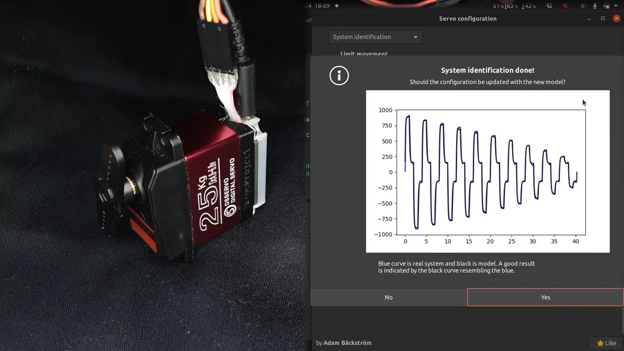
Servo Surgery Teaches Us DIY Encoder Implants
Today, we shall talk about how [Adam Bäckström] took a DS3225 servo and rebuilt it to improve its accuracy, then built a high-precision robot arm with those modified servos to show just how much of an improvement he's got - up to 36 times better positional accuracy. If this brings a déjà vu feeling, that's because we've covered his last demonstration video in an article a few weeks ago, but now, there's more. In a month's time since the last video came out, [Adam] has taken it to the next level, showing us how the modification is made, and how we ourselves can do it, in a newly released video embedded below.
After ordering replacement controller PCBs designed by [Adam] (assembled by your PCBA service of choice), you disassemble the servo, carefully setting the gearbox aside for now. Gutting the stock control board is the obvious next step, but from there, you don't just drop the new PCB in - there's more to getting a perfect servo than this, you have to add extra sensing, too. First, you have to print a spacer and a cover for the control board, as well as a new base for the motor. You also have to print (or perhaps, laser-cut) two flat encoder disks, one black and one white, the white one being eccentric. It only escalates from here!
Both of these disks go inside the motor. That is, you have to pry the servo's DC motor apart, take its base with brushes out, then insert the encoder disks. Then, you snip and file away at the base's plastic parts to free up as much space inside the motor's base as possible, and add the optical encoders in the space you freed. Once that's done, you solder the motor, the optocoupler and the potentiometer connections to the new controller PCB, and assemble the motor back together.
After you're finished with the surgery, you have to calibrate your servo, for which [Adam] shows how to properly set it up mechanically, provides the code you need to run, and even nice GUI tools with controls to tweak servo parameters - his firmware gives us way more power than we could ever expect from a servo like this. All the knobs and sliders available to control coefficients, limits and curves, show us that [Adam] really does understand what makes for proper servo movement. Enough care is put into the documentation, the explanations and the tools for this modification process, that we don't have to be anxious about being left behind if we are to follow these steps ourselves!
In a robot arm, small accuracy errors at the base scale into large errors at the arm's end. If what you crave is high accuracy on a budget, and you have a bit of time to devote to modifying stock servos, this approach might be just what you need, and [Adam] has basically laid all the groundwork for you. Last time we talked about these servo modifications, one of our commenters suggested that this could be a viable successor to the goals of the OpenServo project, and we definitely see where they're coming from. What if you wanted to go even less expensive than this? You could build a servo out of junk DC motors with a "3 cent" microcontroller, then.
We thank [sarinkhan], [Diede] and [BaldPower] for sharing this with us!
#robotshacks #closedloopservomotors #digitalservo #ds3225 #hobbyservo #opticalencoder #robotarm #roboticarm #servocontrol #servodriver #servomotor #servomotors #servos
Robotic Tufting Gun Fires Off CNC Textiles
Often used to make rugs, tufting is a process wherein a hollow needle is used to cram thread or yarn into fabric in some kind of pattern. This can be done by hand, with a gun, or with big machines. Some machines are set up to punch the same pattern quickly over and over again, and these are difficult to retool for a new pattern. Others are made to poke arbitrary patterns and change easily, but these machines move more slowly.
This robotic tufting system by [Owen Trueblood] is of the slow and arbitrary type. It will consist of a modified tufting gun strapped to a robot arm for CNC textile art. Tufting guns are manufactured with simple controls -- a power switch, a knob to set the speed, and a trigger button to do the tufting. Once it's affixed to the robot arm, [Owen] wants to remote control the thing.
The gun's motor driver is nothing fancy, just a 555 using PWM to control a half H-bridge based on input from the speed control potentiometer. [Owen] replaced the motor controller with an Arduino and added an I/O port. The latter is a 3.5 mm stereo audio jack wired to GND and two of the Arduino's pins. One is a digital input to power the gun, and the other is used as an analog speed controller based on input voltage. [Owen] is just getting started, and we're excited to keep tabs on this project as the gun goes robotic.
This isn't the first time we've seen robots do textiles -- here's a 6-axis robot arm that weaves carbon fiber.

Dummy The Robot Arm Is Not So Dumb
[Zhihui Jun] is a name you're going to want to remember because this Chinese maker has created quite probably one of the most complete open-source robot arms (video in Chinese with subtitles, embedded below) we've ever seen. This project has to be seen to be believed. Every aspect of the design from concept, mechanical CAD, electronics design and software covering embedded, 3D GUI, and so on, is the work of one maker, in just their spare time! Sound like we're talking it up too much? Just watch the video and try to keep up!
After an initial review of toy robots versus more industrial units, it was quickly decided that servos weren't going to cut it - too little torque and lacking in precision. BLDC motors offer great precision and torque when paired with a good controller, but they are tricky to make small enough, so an off-the-shelf compact harmonic drive was selected and paired with a stepper motor to get the required performance. This was multiplied by six and dropped into some slick CNC machined aluminum parts to complete the mechanics. A custom closed-loop stepper controller mounts directly to the rear of each motor. That's really nice too.
Stepper controller mounts on the motor rear - smart!
Control electronics are based around the STM32 using an ESP32 for Wi-Fi connectivity, but the pace of the video is so fast it's hard to keep up with how much of the design operates. There is a brief mention that the controller runs the LiteOS kernel for Harmony OS, but no details we can find. The project GitHub has many of the gory details to pore over perhaps a bit light in places but the promise is made to expand that. For remote control, there's a BLE-connected teaching device (called 'Peak') with a touch screen, again details pending. Oh, did we mention there's a force-feedback (a PS5 Adaptive Trigger had to die for the cause) remote control unit that uses binocular cameras to track motion, with an AHRS setup giving orientation and that all this is powered by a Huawei Atlas edge AI processing system? This was greatly glossed over in the video like it was just some side-note not worth talking about. We hope details of that get made public soon!
Threading a needle through a grape by remote control
The dedicated GUI, written in what looks like Unity, allows robot programming and motion planning, but since those harmonic drives are back-drivable, the robot can be moved by hand and record movements for replaying later. Some work with AR has been started, but that looks like early in the process, the features just keep on coming!
Quite frankly there is so much happening that it's hard to summarise here and do the project any sort of justice, so to that end we suggest popping over to YT and taking a look for yourselves.
We love robots 'round these parts, especially robot arms, here's a big one by [Jeremy Fielding], and if you think stepper motors aren't necessary, because servo motors can be made to work just fine, you may be right.
Thanks to [djtano] for the tip!
#robotshacks #ahrs #ble #esp32 #forcefeedback #harmonicdrive #harmonyos #robotarm #roboticarm #steppermotor #stm32 #unity
Client Info
Server: https://mastodon.social
Version: 2025.07
Repository: https://github.com/cyevgeniy/lmst