#USBmidi

Simple DIY Electronic Music Projectsdiyelectromusic.com@diyelectromusic.com
2025-06-29

XIAO ESP32-C3 MIDI Synthesizer – Part 6

Expanding on my previous posts, I thought it might be interesting to see how I might be able to add some additional IO to the MIDI Synth. This is an exploration of some options there.

  • Part 1 – Getting started and getting code running.
  • Part 2 – Swapping the ESP32-C3 for a SAMD21 to get USB MIDI.
  • Part 3 – Taking a deeper look at the SAM2695 itself.
  • Part 4 – A USB MIDI Synth Module using the SAMD21 again as a USB MIDI Host.
  • Part 5 – A Serial MIDI Synth Module using the original ESP32-C3.
  • Part 6 – Pairs the Synth with a XIAO Expansion board to add display and potentiometers.

Warning! I strongly recommend using old or second hand equipment for your experiments.  I am not responsible for any damage to expensive instruments!

These are the key tutorials for the main concepts used in this project:

If you are new to microcontrollers, see the Getting Started pages.

The Synth Grove Connector

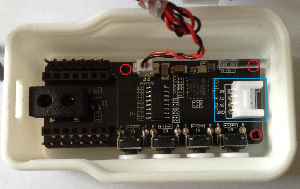
One option to immediately explore for me was the Grove connector on the Synth – highlighted by the blue rectangle in the photo below. I’m thinking at this stage of the XIAO Expander Module (more here) and how that might give some options for easily hooking up to the Synth.

There one obvious issue with this, and one not so obvious issue.

First, of course, there is no access to this connector through the case. My initial thought was to simply remove the PCB from the case and use it as a stand-alone board. On initial inspection it seemed that there were two screws holding it down. Not so, a more thorough inspection (after remove the two screws and still not being able to remove it), revealed a third screw underneath the “light pipe” for the LEDs.

Unfortunately that light pipe is pretty well wedged into the case making removal particularly tricky. But without removing the light pipe, it isn’t possible to get to the screw at all.

I did wonder about making a hole in the 3D printed case. A better option might be to get hold of the published 3D print files and add a hole and make my own (they are available via the product page).

But both options would probably end up changing the original case somehow – even if printing my own, I still need to get the original PCB out somehow and that brings me back to the light pipe issue.

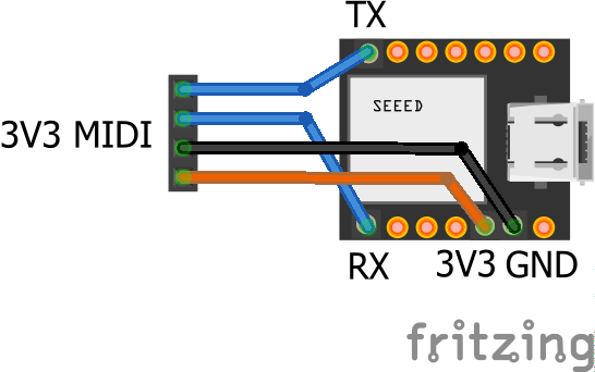
The second issue isn’t quite so obvious. In that photo we can see that the pins for the Grove connector are labelled as follows (top to bottom):

  • NC
  • TX
  • 5V
  • GND

The UART on the XIAO expander board, which I’d like to use, is labelled:

  • RX7
  • TX6
  • 3V3
  • GND

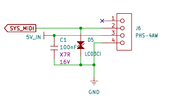
Checking in with the Synth schematic, the connector is wired as follows:

SYS_MIDI connects to the MIDI_IN pin of the SAM2695, so actually connecting “TX to TX” in this instance should be ok.

5V might be an issue though, as it really does look like (to me) that it really means 5V – it is the input to the TPL740F33 that generates the 3V3 power signal, as well as feeding the amplifier directly. The datasheet of the TPL740F33 does seem to imply that if receiving 3V3 it can still generate 3V3 so it might be ok? The amplifier obviously won’t be as powerful though running off 3V3.

Anyway, for now, instead I’ve just opted to use the GPIO again, wired into the expansion sockets with the XIAO removed.

At the XIAO expander end, I’ve used the additional pins rather than the Grove connector, as they support a 5V output.

The downsides to this approach:

  • I’m not using the Grove connectors, which would have been really neat.
  • I have no access to the four buttons on the XIAO MIDI Synth.

But I do now have access to two I2C Grove connectors, a GPIO Grove, and the RX part of the UART Grove too as well as the on-board display.

If a XIAO SAMD21 is used, then the previous code for USB to the Synth can be used directly – see XIAO ESP32-C3 MIDI Synthesizer – Part 2.

If the XIAO ESP32-C3 is used, then an additional serial MIDI connection is required. This can be connected to the Grove UART connector (using the RX pin, and leaving TX unconnected) or the RX pin of the additional 8-way pin header on the expansion board. Then the code from this will work directly: XIAO ESP32-C3 MIDI Synthesizer – Part 5.

Adding a Display and Program Control

I already have some code that has done this for a XIAO on an expansion board here XIAO SAMD21, Arduino and MIDI – Part 6.

But for this to work usefully with the Synth module, I need to adjust the routing so that MIDI goes from USB to serial, but the program change messages are also sent via serial to the synth module. That has already been address in previous parts, to I just need to merge the code with that from XIAO ESP32-C3 MIDI Synthesizer – Part 4.

This is the result.

There is a bit of jitter on the analog pot, but that is only because I’m using the original fairly simplified algorithm to detect changes. If I was fussed about it, I’d reuse the averaging class from Arduino MIDI Atari Paddles. And to be honest, a capacitor on the pot would probably go quite a long way too…

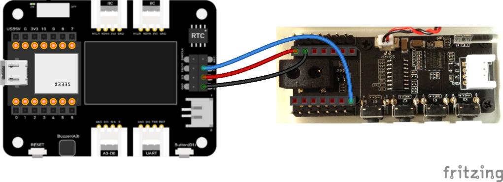
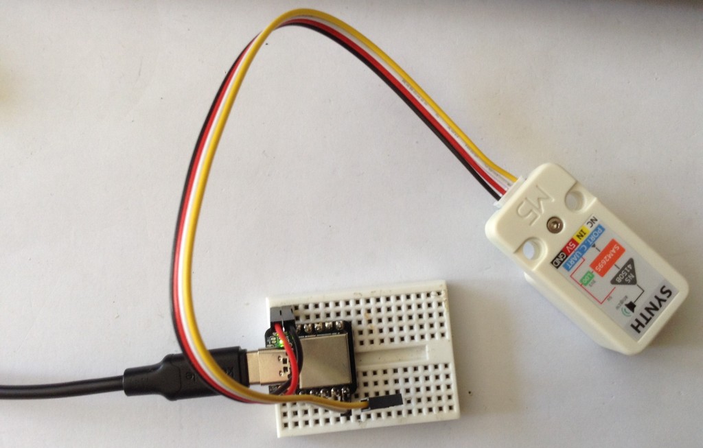
As a test, I also powered the device from the Grove UART port connecting it as follows:

  • Expander GND – GND Synth
  • Expander 3V3 – 5V IN Synth
  • Expander TX – RX/D6 Synth
  • Expander RX – N/C

And this all worked fine. So I think a Grove to Grove lead would work fine if I had access to the Synth’s Grove port.

This does mean that the exact same code can work with the M5 Synth module using a Grove to Grove lead. The downside of this, even though it is a lot simpler in connectivity terms, is that there is now external audio out like there is on the XIAO Synth.

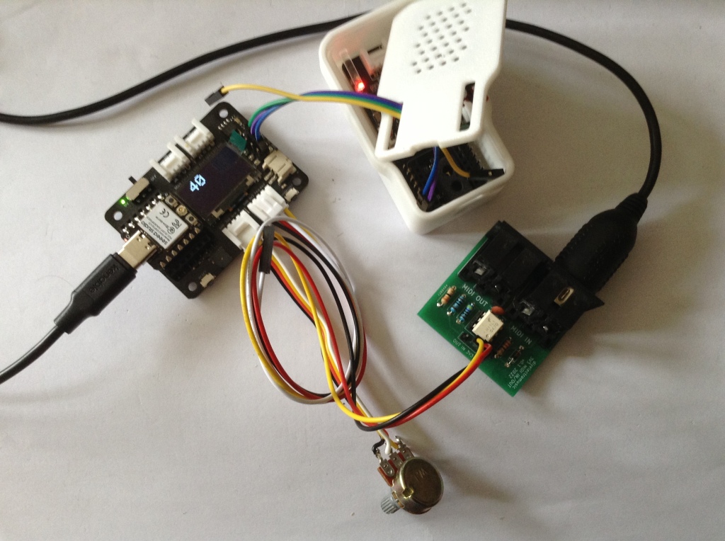
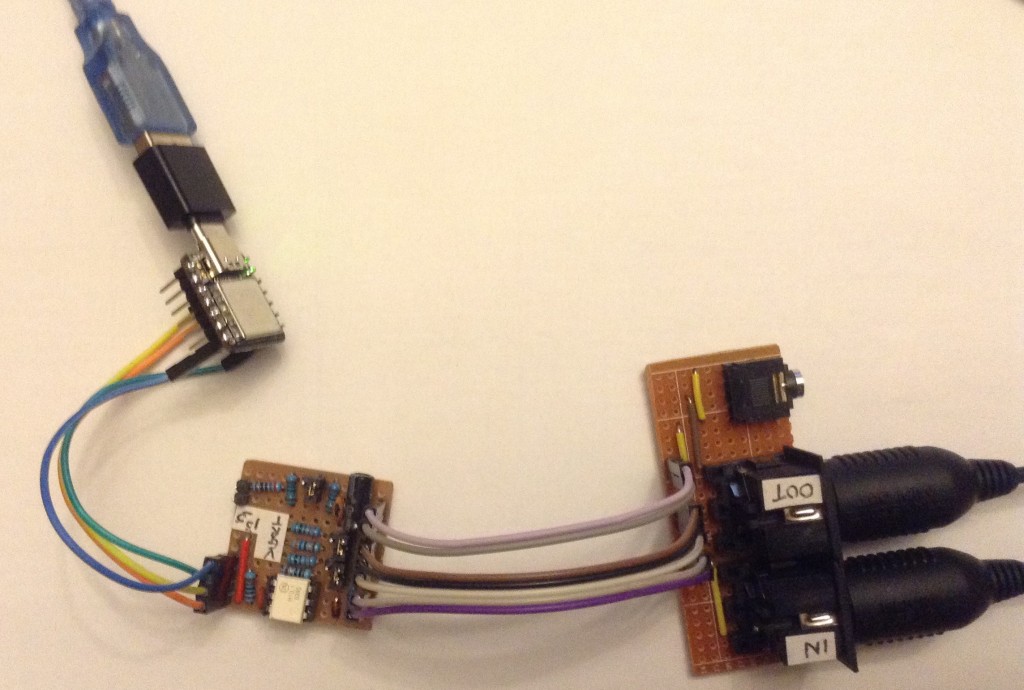
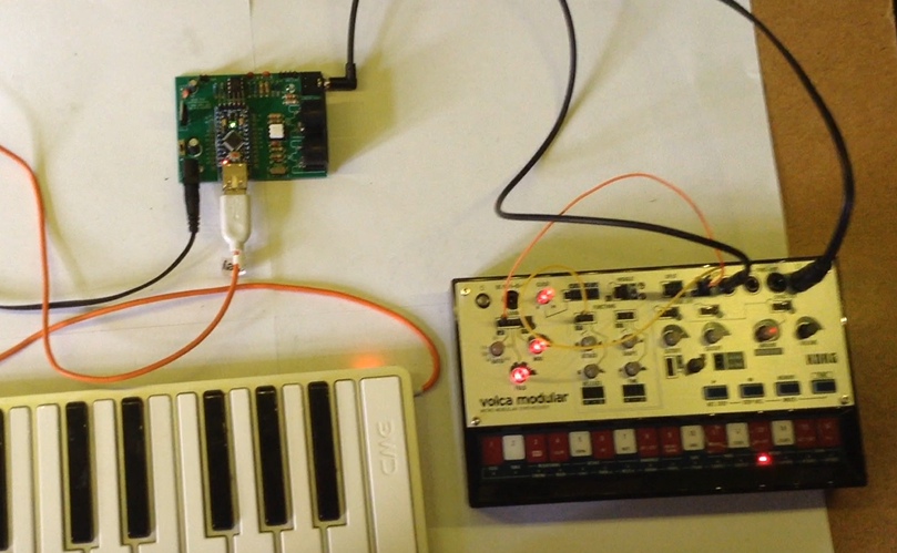
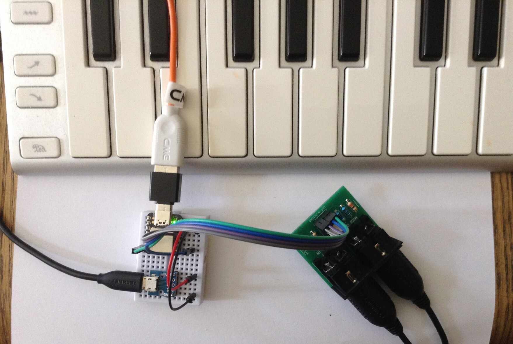
For completeness the same code can be used with the XIAO ESP32-C3 and serial MIDI, see the photo at the start of this blog.

To turn off all USB handling in the code, the following must be commented out:

//#define HAS_USB
//#define SER_TO_USB
//#define MIDI_USB_PCCC

For other parts of the code, the Arduino abstraction for A0 maps over to the ESP32-C3 fine. The only thing to watch out for is the increased analog resolution from 10 to 12 bits, but a call to analogReadResolution(10) drops that back to the expected 10 bits.

Oh and the Serial port to use is different:

  • XIAO SAMD21: Serial1
  • XIAO ESP32-C3: Serial0

Find it on GitHub here.

Closing Thoughts

If I can be bothered, it would be nice to actually display the General MIDI voice name on the display. The SAM2695 also has its MT-32 mode, so having some means of selecting that might be interesting too.

And so far I’ve largely only messed about with driving it on a single MIDI channel, so there is a lot more that could be done there.

Kevin

#controlChange #esp32c3 #midi #programChange #SAM2695 #samd21 #usbMidi #xiao

Simple DIY Electronic Music Projectsdiyelectromusic.com@diyelectromusic.com
2025-06-28

XIAO USB Device to Serial MIDI Converter

Having recently revisited the CircuitPython USB to Serial MIDI Router as part of XIAO ESP32-C3 MIDI Synthesizer – Part 2 it reminded me I didn’t really have a simple Arduino USB device to serial MIDI for the XIAO. So this is filling that gap.

Warning! I strongly recommend using old or second hand equipment for your experiments.  I am not responsible for any damage to expensive instruments!

These are the key Arduino tutorials for the main concepts used in this project:

If you are new to Arduino, see the Getting Started pages.

Parts list

  • XIAO SAMD21
  • Serial MIDI module
  • Breadboard and jumper wires

The Circuit

A 3V3 serial module can be hooked up to the TX/RX pins of the XIAO as shown above.

The Code

This is largely a simplification of the code used for XIAO SAMD21, Arduino and MIDI – Part 4 to use just the standard serial port and USB device MIDI.

There is one option at the top to determine how the serial port ought to be routed. There are two options:

  • Serial to USB. This allows a full bi-directional serial <-> USB.
  • Serial to Serial. This allows both USB and Serial RX to route to Serial TX.

In the other direction, USB always gets routed to the Serial port.

Find it on GitHub here.

Closing Thoughts

Often I find I’ve missed out a simpler use-case in pursuit of a more complex one. This was one of those times so hopefully that is now fixed.

In the above photo I’m using it as a USB to serial router for my M5 Stack Synth module based on the SAM2695 that I’ve been playing with. The Synth is powered from the XIAO’s 5V and GND and connected to the TX/D6 pin. This allows me to use USB MIDI which gets routed to the M5 Synth hanging off the XIAO TX pin.

There is more on that particular synth chip here: XIAO ESP32-C3 MIDI Synthesizer – Part 3.

Kevin

#m5stsack #midi #SAM2695 #samd21 #usbDevice #usbMidi #xiao

Simple DIY Electronic Music Projectsdiyelectromusic.com@diyelectromusic.com
2022-04-21

CircuitPython USB to Serial MIDI Router

I’ve indirectly used USB and Serial MIDI with CircuitPython a few times now, but haven’t explicitly shown how to use it as a simple USB (device) to serial MIDI converter.  This project shows how to do that.  Any CircuitPython device should be usable like this, but I’ve used this as an excuse to do something with the Seeedstudio Seeeduino XIAO board.

Warning! I strongly recommend using old or second hand equipment for your experiments.  I am not responsible for any damage to expensive instruments!

These are the key tutorials for the main concepts used in this project:

If you are new to microcontrollers, see the Getting Started pages.

Parts list

The Circuit

If you are using a Raspberry Pi then the circuit is one I’ve used several times already.  Connect up your 3V3 compatible MIDI module to GND, 3V3, RX and TX.

If you are using a Trinket M0 then there is a really good learning guide on the Adafruit site that will get you going – again you’ll need the same GND, 3V3, RX and TX pins.

In my case, I wanted an excuse to do something with a Seeedstudio Seeeduino XIAO module.  This is a SAMD21G based module with a USB-C connector, and would need to be connected up as follows.

The general idea is that the CircuitPython device will connect to a PC (or other USB host) as a USB MIDI device and forward any MIDI traffic between the USB MIDI link and a connected serial MIDI module.

The Code

The basic idea is relatively straightforward once your device is up and running with Circuitpython itself (see the Adafruit guides for help to get this far!):

Set up the USB MIDI deviceSet up the serial MIDI devicewhile:    IF there is a USB MIDI IN message THEN        Send it out on the serial MIDI OUT port    IF there is a serial MIDI IN message THEN        Send it out on the USB MIDI OUT port

The only slight quirk is that I try to filter out unrecognised MIDI messages to limit the forwarded traffic, but if you haven’t imported the adafruit_midi representation of a MIDI message, then the code will not recognise it!  So I need to pull in the various MIDI message representations at the start of the file.

Not being a python person myself really, I may well be missing something and there might be a more elegant way to do this, but I have to say I’m not really a fan of how MIDI is implemented in CircuitPython as it feels too hidden away behind “clever layers” for my liking.  But having said that, there really is no easier way (at present) for making a USB MIDI device than CircuitPython.

The code also supports flashing an LED on reception of a MIDI event.  For the XIAO this looks like the following:

led = digitalio.DigitalInOut(board.D13)led.direction = digitalio.Direction.OUTPUTled.value = Truedef ledOn():    led.value = Falsedef ledOff():    led.value = True

With the XIAO the LED is on when led.value = False.  For the Raspberry Pi Pico, it would be different again, something like the following (untested, but pasted in from my other code):

led = digitalio.DigitalInOut(board.GP25)led.direction = digitalio.Direction.OUTPUTdef ledOn():    led.value = Truedef ledOff():    led.value = False

Some boards support the Python/CircuitPython “built in LED” identifier – you might be able to get away with using board.LED above, but the True/False logic still needs setting up correctly for your board.  Some boards are now using board.LED_INVERTED too, so just see what works.

One way to see what is supported is to do the following in the REPL shell when connected to the board:

>>> import board
>>> dir (board)

Also, whilst the XIAO and other boards have board.TX and board.RX defined for the default serial port, the Raspberry Pi Pico does not, so the code to initialise the serial MIDI will also have to be changed to look more like the following for the Pico (this is to use UART 0 on GP0 and GP1).

uart = busio.UART(tx=board.GP0, rx=board.GP1, baudrate=31250, timeout=0.001)

The original was:

uart = busio.UART(tx=board.TX, rx=board.RX, baudrate=31250, timeout=0.001)

Find the XIAO version on GitHub here.

Closing Thoughts

As always, I continue my love/hate relationship with CircuitPython (and Python more generally), but I can’t deny, this is still probably the easiest way to get a USB MIDI device to serial MIDI converter up and running!

Now USB MIDI Host… well that is another story…

Kevin

#circuitpython #midi #raspberryPiPico #trinket #usbMidi #xiao

IMG_6117XIAO MIDI_bb

So, continuing with #USBmidi on #OSX #Monterey. Now that I have found which of my #USB #MIDI devices works electrically, it turns out #Ardour can access this interface successfully.

However, I am having trouble using the MIDI interface with #DecentSampler (standalone) or #Carla (my favorite standalone plugin host on all OSses).

Both Decent Sampler and Carla don't offer a device selection for MIDI devices.

So my #MacOS problem melts down to a) an electronics problem with cheap MIDI interfaces not being opto-coupled as they should be, even endangering the USB-C ports of the MacBook Pro 2017, and b) Certain pieces of software not having a MIDI settings dialog, or there is some mechanism that I don't know yet.

@falktx – do you perhaps have a quick hint on how to get MIDI input into Carla on OSX?

So now I tried some different #USBmidi device with #OSX #Monterey and this time I don't have dangerous leaking current.

(Funnily enough, this one does not work with #IOS, while the shitty one does work with IOS bot not #MacOS.

Now I'm back on the software side. The interface does show up as being ready in the “audio midi setup”, but how can I actually use it with #Carla or #DecentSampler now?

#Fedihelp on #MIDI on #OSX #Moneterey out there?

I have this noname #USBmidi cable. It works class compliant out of the box on #Linux / #UbuntuStudio 24.04. A tiny LED on the USB plug shows incoming MIDI, which I can also see in #GMIDImonitor after routing it in #Patchance. (#Pipewire audio system.)

On #MacOS I am lost. The tiny LED does not light up on incoming MIDI. Apparently this USB device is not even activated by the OS.

It also cannot by detected in “audio midi setup”.

I mean, this is OSX, the supposedly easy OS for creative people… what's going on?

EDIT: It turns out that this might be not an OSX problem. The USB MIDI does not show up as soon as the MIDI is plugged in. I guess this is a leakage current problem which might in the end even destroy USB ports. Power supplies without ground connections are prone to this error (those by Apple, too). A MIDI interface should be opto-coupled, but many actually aren't.

Continued in 🧵

Simple DIY Electronic Music Projectsdiyelectromusic.com@diyelectromusic.com
2025-05-24

USB MIDI to Serial and CV/GATE

This project uses my Arduino Pro Mini MIDI USB CV PCB for a USB MIDI to Serial MIDI and CV/GATE device that has a CV/GATE that is compatible with my Korg Volca Modular.

It takes MIDI NoteOn/NoteOff and translates them into CV that can be used to set the pitch of a CV/GATE synth.

IMPORTANT: I strongly recommend that you do not connect this to your Volcas. I am not an electronics person but have accepted the risk of causing a possibly expensive problem. I will not be held responsible if you end up doing the same.

https://makertube.net/w/puRwMGeELa5zq3YhMrMC4h

https://makertube.net/w/cPjFeqigcrBHgMMPLjPNPb

Warning! I strongly recommend using old or second hand equipment for your experiments.  I am not responsible for any damage to expensive instruments!

If you are new to Arduino, see the Getting Started pages.

The Circuit

This is an application for my completed Arduino Pro Mini MIDI USB CV PCB.

The Code

The board was designed to require a PWM output on D3. With hindsight, D9 might have been more useful as D9 is a “Timer 1” timer on the ATMega328, but D3 is a “Timer 2” timer. The former are 16-bit timer/counters. The latter are only 8-bit.

No matter. I still have 255 levels of PWM to play with.

The initial PWM criteria I wanted were:

  • No prescalar – run at full CPU speed. In the case of a 3V3 Pro Mini this is 8MHz.
  • Use FastPWM mode – this will count up and then reset to zero.
  • Use a TOP value of 255 – the maximum.
  • Use the OC2B output, which is connected to D3. OC2A is not used.
  • Use the mode where OC2B is cleared on compare match; set at 0 (BOTTOM).
  • The PWM value is therefore written into OCR2B.

At some point the code will have to translate from MIDI note number over to a PWM value. My previous project mapped MIDI note C2 (36) onto 0V and went up from there for 5 octaves to C7 (96). This is a range of 60 steps, so actually, revisiting the PWM code, if we change the mode to use an alternative TOP Value of 239, that means each MIDI note corresponds to a specific step of 4. That would be pretty useful!

So the updated PWM criteria is now as follows:

  • No prescalar – still run at full CPU speed. In the case of a 3V3 Pro Mini this is 8MHz.
  • Use FastPWM mode – this will count up and then reset to zero.
  • Use a TOP value of OCR2A, which will be set to 239.
  • Use the OC2B output, which is connected to D3. OC2A is not used.
  • Use the mode where OC2B is cleared on compare match; set at 0 (BOTTOM).
  • The PWM value is therefore written into OCR2B.

The PWM operating frequency is given by a formula in the datasheet, but is basically the time it takes for the counter to count from 0 to 239 and reset, whilst running at 8MHZ. So the PWM frequency = 8000000 / 240 = 33.3kHz.

At such a frequency the (now updated) PWM filter components chosen give a pretty smooth output between 0V and 3.3V, which are them amplified using the OpAmp for a 0V to 5V range.

Note: No interrupts are required for the operating of PWM in this manner. We can just update the PWM value whenever is useful during the operation of the code.

The complete PWM code is thus as follows

void initPwm() {
pinMode(3, OUTPUT);
TCCR2A = _BV(COM2B1) | _BV(WGM21) | _BV(WGM20);
TCCR2B = _BV(WGM22) | _BV(CS20);
OCR2A = 239;
}

void setPwm (uint8_t pwmval) {
OCR2B = pwmval;
}

The value used for PWM will only be active for 0-239. Any value of 240 or higher will just be considered “always on”.

This all means that converting from MIDI to PWM value is now pretty trivial:

#define MIDI_LOWEST_NOTE  36 // C2
#define MIDI_HIGHEST_NOTE 95 // C7
uint8_t midi2pwm (uint8_t note) {
if (note < MIDI_LOWEST_NOTE) note = MIDI_LOWEST_NOTE;
if (note > MIDI_HIGHEST_NOTE) note = MIDI_HIGHEST_NOTE;
return (note - MIDI_LOWEST_NOTE) * 4;
}

Logging the average voltage for each MIDI note (pre and post amplification) gives me the following:

C20.080.08C30.721.06C41.352.03C52.023.01C62.653.95C73.284.90

Plotting these on a graph looks like this:

That is a pretty good linear response, but is slightly under in terms of the top-end output. At 1V/oct a semitone is around 83mV, so dropping 0.1V at the top ought to be dropping a semitone.

But jumping through the octaves it sounds all right to me. It’s definitely not dropping a semitone anyway, so I’m not sure what is going on. I might need to come back to this one!

The rest of the code is fairly straightforward MIDI reception and processing that I’ve done several times before now. There are a few design notes:

  • Automatic MIDI THRU is turned off or both serial and USB MIDI.
  • When a note that is not on the required channel or is out of the C2-C7 range is received, it is ignored.
  • Anything received over USB is automatically sent to the serial OUT and anything received over serial is automatically sent to the USB OUT.
  • NoteOff is only processed if received for the currently playing note.
  • Consecutive NoteOn messages update the CV and replace the previously playing note.
  • There is an option for a GATE type operation:
    • GATE goes HIGH on NoteOn.
    • GATE goes LOW on NoteOff.
  • Or for a TRIGGER pulse type operation:
    • GATE goes HIGH on NoteOn.
    • GATE remains HIGH for a defined time (e.g. 10mS) then automatically goes off.
  • On reception of NoteOff there are several possible options for what to do with the CV:
    • Leave it and do nothing. This allows any envelopes to complete on removal of the GATE signal with no change of CV. But the CV will remain at the last level until a new note is received.
    • Set it to the NoteOff pitch received. Although in reality this is probably going to be the same as “do nothing”.
    • Set the CV to 0. This means there is no “dangling” CV voltage, but the synth will probably respond to the changing CV.
  • I’ve left in a compile-time PWMTEST mode that just plays the different Cs for measuring voltages, and so on.

Find it on GitHub here.

Closing Thoughts

This actually seems to work surprisingly well. I did wonder if the apparent inaccuracies of the output might cause an issue, but it doesn’t seem to.

The PWM filter issue was annoying, but on the one hand, it was a lot easier to build and debug with a PCB in hand; but of course on the other hand, if I’d done it first on solderless breadboard, the problem would have almost certainly be spotted and the design would probably have been right.

This has only looked at a pitch CV. It would be interesting at some point to do some kind of MIDI CC to CV control device.

Kevin

#arduinoProMini #cv #define #korg #midi #midi2cv #usbMidi #volca

2025-05-24

The CME H4 MIDI WC is a self-sufficient USB MIDI host with a pair of DIN MIDI INs and OUTs as well as USB C and A.

The crucial thing is that you can extend the USB A with a hub to expand it to up to eight ports. You need to connect to a PC to set up that telephone exchange, but after that y're good to go.

Sure, I guess you could do all this with a Raspberry Pi, but it's actually cheaper than either that or one of those Kentons. Three thumbs up!

#midi #usb #usbmidi #midithru #omg

Pete Prodoehl 🍕rasterweb
2024-08-24

@paulrickards Wow! Good call... That's it.

• USB HID Current Required: 250mA

• USB MIDI Current Required: 100mA

I wonder if there's a workaround...

2024-02-19

One last thing I definitely wanted for my PicoDexed was the option for PWM output. This post is by way of a short coda detailing how to do PWM on a Raspberry Pi Pico.

  • Part 1 where I work out how to build Synth_Dexed using the Pico SDK and get some sounds coming out.
  • Part 2 where I take a detailed look at the performance with a diversion into the workings of the pico_audio library and floating point maths on the pico, on the way.
  • Part 3 where I managed to get up to 16-note polyphony, by overclocking, and some basic serial MIDI support.
  • Part 4 for the full MIDI implementation, voice loading, SysEx control and USB-MIDI.
  • Part 5 details different options for building hardware to run PicoDexed.

The latest code can be found on GitHub here: https://github.com/diyelectromusic/picodexed

Warning! I strongly recommend using old or second hand equipment for your experiments.  I am not responsible for any damage to expensive instruments!

If you are new to microcontrollers, see the Getting Started pages.

PWM Output Circuit

The official “Hardware Design with the RP2040” guide includes a PWM circuit as follows (see section 3.4.1).

Several others have used a slightly simplified version of this circuit, essentially omitting the buffer stage (U3) and perhaps only implementing a single channel. See for example – Raspberry Pi Pico PWM Audio Output Circuit (Jeremy S. Cook) and “pico-pwm-audio” (Robin Grosset).

An alternative is this circuit used by Tod Kurt for his Circuitpython-tricks“The output circuitry to get line-out levels is a simple 10:1 voltage-divider and a 1uF capacitor to recenter the signal around 0 volts”:

I’m going with Jeremy S. Cook and Robin Grosset and using the following (diagram from here):

This is my solderless breadboard version of the above:

Raspberry Pi Pico Audio PWM

There appears to be two ways of getting audio style PWM signals out of a Pico:

  • Use the PWM peripherals.
  • Use the PIO.

It would appear that Raspberry Pi’s pico_audio library in the pico-extras repository uses PIO. I haven’t found a clear explanation as to why the built-in PWM peripherals haven’t been used.

Here are some other resources that show alternative descriptions of PWM for audion on a Pico:

As I’m using the pico_audio library for I2S audio, I’m going to use the default PWM pico_audio library too.

To initialise the pico_audio PWM library requires the following:

const audio_pwm_channel_config_t config =
{
.core = {
.base_pin = base_pin,
.dma_channel = dma_ch,
.pio_sm = pio_sm
},
.pattern = 3,
};

const struct audio_format *output_format;
output_format = audio_pwm_setup(pAudioFormat, -1, &config);
bool status = audio_pwm_default_connect(pBufferPool, false);
audio_pwm_set_enabled(true);

Everything else is the same as for I2S.

At present, overclocking the Pico causes the PWM frequencies to be messed up, so for now the recommended configuration is 8-note polyphony, 24000 sample rate and no overclocking.

The build uses GPIO 20 for PWM.

Closing Thoughts

I’ve uploaded a prototype PWM UF2 file to GitHub too now in case anyone wants to give that a go too: https://github.com/diyelectromusic/picodexed

Hopefully there is enough information in the above to get something up and running.

Kevin

https://diyelectromusic.wordpress.com/2024/02/19/raspberry-pi-pico-synth_dexed-part-6/

#dx7 #midi #picodexed #pwm #raspberryPiPico #usbMidi

2024-02-18

Ok, ignore my last comment about Part 4 being my last post on this topic. I thought I ought to pull together all the hardware notes on how to build one as I haven’t really written that down anywhere.

So this shows the connections required between the Pico, I2S DAC and MIDI IN.

  • Part 1 where I work out how to build Synth_Dexed using the Pico SDK and get some sounds coming out.
  • Part 2 where I take a detailed look at the performance with a diversion into the workings of the pico_audio library and floating point maths on the pico, on the way.
  • Part 3 where I managed to get up to 16-note polyphony, by overclocking, and some basic serial MIDI support.
  • Part 4 for the full MIDI implementation, voice loading, SysEx control and USB-MIDI.
  • Part 6 includes details of how to use PWM output.

The latest code can be found on GitHub here: https://github.com/diyelectromusic/picodexed

Warning! I strongly recommend using old or second hand equipment for your experiments.  I am not responsible for any damage to expensive instruments!

If you are new to microcontrollers, see the Getting Started pages.

The Circuit

The easiest way to get a PicoDexed up and running for me, is to use one of my MIDI Proto PCBs and the Pimoroni I2S Audio Pack. This does not allow for any debug output.

Note the jumpers are set to use UART 1 on GP4 and GP5.

If only USB-MIDI is required, then the Audio Pack can be plugged directly onto the back of the Pico, in which case simply plugging into the Pico via USB to a computer and connected up the audio out will work.

It is also possible to use any 3V3 compatible MIDI module. The following shows the use of a Pimoroni “dual expander” with a MIDI module connected to GND, 3V3_OUT and GP5 (RX1).

This has the advantage that all other GPIO pins are available, so it is relatively straight forward to include a debug link via GP0/GP1 for UART 0.

A Solderless Breadboard Circuit

Of course it is also possible to build everything on a solderless breadboard.

The diagram below shows how a cheap GY-PCM5102 module can be used as the I2S DAC and a serial MIDI interface (optional) can be built using my standard 3V3 MIDI IN circuit.

This also allows for some debug output using UART 0 (GP0/GP1).

Things to note:

  • The PCM5102 board will have to have solder jumpers on the rear set as follows: 1=L, 2=L, 3=H, 4=L. Sometimes these come preconfigured with solder bridges, sometimes with zero-ohm SMT resistors, and sometimes with no connection made at all. More details here.
  • I always get pins 4 and 5 mixed up on MIDI DIN sockets. Here is my MIDI Connections Cheat Sheet which may help.

Pico GPIO Usage

The following GPIO pins are in use or allocated:

GP0Debug UART TX (unused at present)GP1Debug UART RXGP4MIDI TX (unused at present)GP5MIDI RXGP9I2S Data (DATA, DIN)GP10I2S Bit Clock (BCK)GP11I2S “Left/Right” Clock (LCK, LRCK, LR_CLOCK)GP20Optional: PWM outputGP22Optional: Mute pin for the Pimoroni Audio Pack (not used)VSYS5V power to DAC (if required)3V3_OUT3V3 power to MIDI IN (if required)GND

PWM Audio Output

It is possible to use PWM audio output on the Pico. Full details can be found here: Raspberry Pi Pico Synth_Dexed? – Part 6.

But this is a lot more limited than I2S and the quality is a lot poorer too. As a DAC can be obtained quite cheaply, the use of an I2S DAC is strongly recommended.

Closing Thoughts

I’ve uploaded a prototype UF2 file to GitHub in case anyone wants to give it a go: everything can be found here: https://github.com/diyelectromusic/picodexed

Hopefully there is enough information in the above to get something up and running.

Kevin

https://diyelectromusic.wordpress.com/2024/02/18/raspberry-pi-pico-synth_dexed-part-5/

#dx7 #midi #pcm5102 #picodexed #raspberryPiPico #usbMidi

2024-02-16

I was going to leave things at Part 3 blog-wise, and just get on with filling in the gaps in code now, but I’ve come back to add a few more notes. But this is likely to be the final part now.

Recall so far, I have:

  • Part 1 where I work out how to build Synth_Dexed using the Pico SDK and get some sounds coming out.
  • Part 2 where I take a detailed look at the performance with a diversion into the workings of the pico_audio library and floating point maths on the pico, on the way.
  • Part 3 where I managed to get up to 16-note polyphony, by overclocking, and some basic serial MIDI support.

This is building on the last part and includes notes on how I’ve implemented the following:

  • Fuller MIDI support, including control change, program change and pitch bend messages.
  • Voice and voice banks, selectable over MIDI.
  • MIDI SysEx messages for voice parameters.
  • USB MIDI device support.

The latest code can be found on GitHub here: https://github.com/diyelectromusic/picodexed

Warning! I strongly recommend using old or second hand equipment for your experiments.  I am not responsible for any damage to expensive instruments!

If you are new to microcontrollers, see the Getting Started pages.

MIDI Support

I’m not going to walk through all the details of how I’ve added MIDI but suffice to say that once again the implementation owes a lot to MiniDexed and the Arduino MIDI Library.

At the time of writing the following are all supported as they were already supported in Synth_Dexed, so I just needed to glue the bits together.

Channel Voice Messages (only channel 1 at present)

0x80MIDI Note Offnote=0..127, vel=0..1270x90MIDI Note Onnote=0..127, vel=0..1270xA0Channel Aftertouchnote=0..127, val=0..1270xB0Control ChangeSee below0xC0Program Change0..31 (If used with BANKSEL)
0..127 (if used independently)0xE0Pitch Bend0..16383 (in LSB/MSB 2×7-bit format)

Channel Control Change Messages

0Bank Select (MSB)01Modulation0..1272Breath Control0..1274Foot Control0..1277Channel Volume0..12732Bank Select (LSB)0..864Sustain<=63 Off, 64=> On65Portamento<=63 Off, 64=> On95Master Tune0..127 *120All Sound Off0123All Notes Off0126Mono Mode0 **127Poly Mode0

* There is a bug with the master tuning. It ought to accept -99 to 99 I believe, but only 0..99 will actually register and there is no way to send -99 via MIDI at the moment. I need to read up on what is going on here and what it ought to do!

** The Mono Mode parameter has the option for specifying how many of the playable voices can be dedicated to mono mode (at least I think that is what it is saying). I only support a value of 0 which I believe is meant to mean “all available voices”.

System Messages

0xF0..0xF7Start/End System ExclusiveSee below0xFEActive SensingFiltered out0xFnOther system messagesIgnored

System Exclusive Messages

Any valid Yamaha (DX) system exclusive messages are passed straight into Synth_Dexed. A Yamaha (DX) message has the following format (see the “DX7IIFD/D Supplemental Booklet: Advanced MIDI Data and Charts”):

F0 - start SysEx message
43 - Yamaha manufacturer ID
sd - s=substatus (command class:0,1,2); d=device ID (0..F)
.. data ..
F7 - end SysEx message

The device ID can be set using the UI on a real DX7 to a value between 1 and 16, which becomes a value between 0 and 15 (0..F) as part of the SysEx message (see “DX7IIFD/D Supplemental Booklet: Advanced MIDI Applications, Section 8”). It is a Systems Exclusive value analogous to the MIDI channel for regular channel messages.

There are a range of Sys Ex parameter settings that have been passed onto Synth_Dexed as follows:

Mono Mode0..1Pitch Bend Range0..12Pitch Bend Step0..12Portamento Mode0..1Portamento Glissando0..1Portamento Time0..99Mod Wheel Range0..99Mod Wheel Target0..7Foot Control Range0..99Foot Control Target0..7Breath Control Range0..99Breath Control Target0..7Aftertouch Range0..99Aftertouch Target0..7Voice Dump Load<156 bytes of voice data>Voice Parameter SetParameter=0..155; Data=0..99

At this stage, all of the MIDI support is on a “it’s probably something like this” basis, so it will evolve as I find out what it is meant to be doing!

Voice and Bank Loading

Banks of voices are programmed directly into the code. There is a python script from Synth_Dexed that will take a .syx format voice bank and generate a block of C code. I’ve included a script to download the main 8 banks of standard DX voices and run the script:

#!/bin/sh

# Get voices from
# https://yamahablackboxes.com/collection/yamaha-dx7-synthesizer/patches/

mkdir -p voices

DIR="https://yamahablackboxes.com/patches/dx7/factory"

wget -c "${DIR}"/rom1a.syx -O voices/rom1a.syx
wget -c "${DIR}"/rom1b.syx -O voices/rom1b.syx
wget -c "${DIR}"/rom2a.syx -O voices/rom2a.syx
wget -c "${DIR}"/rom2b.syx -O voices/rom2b.syx
wget -c "${DIR}"/rom3a.syx -O voices/rom3a.syx
wget -c "${DIR}"/rom3b.syx -O voices/rom3b.syx
wget -c "${DIR}"/rom4a.syx -O voices/rom4a.syx
wget -c "${DIR}"/rom4b.syx -O voices/rom4b.syx

./synth_dexed/Synth_Dexed/tools/sysex2c.py voices/* > src/voices.h

This only needs to be run once to create the src/voices.h file which is then included in the build.

Voices have the following format:

uint8_t progmem_bank[8][32][128] PROGMEM =
{
{ // Bank 1
{<--128 bytes of packed voice data-->} // Voice 1
...
{<--128 bytes of packed voice data-->} // Voice 32
}
{ // Bank 2
...
}
...
{ // Bank 8
{<--128 bytes of packed voice data-->} // Voice 1
...
{<--128 bytes of packed voice data-->} // Voice 32
}
}

The system assumes 8 banks of 32 voices each, in the “packed” SYX header format, meaning each voice consists of 128 bytes.

MIDI Bank and Voice Selection

As there are only 8 banks, only BANKSEL (LSB) values 0..7 are valid. Program Change will work in two ways however:

  • 0..31 will select voices 1 to 32 in the current bank.
  • 31..127 will select voices from the following three adjacent banks.

To select any voice in all 8 banks thus requires the following sequence:

BANKSEL MSB = 0
BANKSEL LSB = 0..7
PROG CHANGE = 0..31

But if bank selection is skipped, then Program Change messages can still be used to select one of the first 128 voices across four consecutive banks.

USB MIDI

The Raspberry Pi Pico SDK uses the TinyUSB protocol stack to implement USB device or host modes and there is an additional option to implement a second USB host port using the Pico’s PIO.

However, USB MIDI appears to only be supported for USB devices at the time of writing, so I’m just using the built-in USB port as a USB device, based on the code provided as part of the TinyUSB examples (more details of how to get basic USB MIDI running here).

TinyUSB MIDI supports two interfaces for reading data, and this wasn’t immediately obvious from the example as that is only sending data and ignores anything coming in.

  • USB MIDI Stream mode: this will fill a provided buffer with MIDI data received over USB.
  • USB MIDI Packet mode: this will return each 4-byte USB packet individually.

From what I can see of the USB MIDI Spec, all MIDI messages are turned into 4-byte packets for transferring over USB. All normal MIDI messages will consist of 1, 2 or 3 byte messages, and so will fit in a packet each – any unused bytes are padded with 0.

However SysEx messages are a little more complicated and have to be split across multiple packets.

This is the format for a USB MIDI Event Packet (see the “Universal Serial Bus Device Class Definition for MIDI Devices”, Release 1.0):

The code index number is an indication of the contents of each packet. For channel messages, this is basically a repeat of the MIDI command, so a MIDI Note On message might look something like the following:

09 92 3C 64
Cable 0
Code Index Number 9
MIDI Cmd 0x90 (Note On)
MIDI Channel 3 (0x0=1; 0x1=2; 0x2=3; ... 0xF=16)
Note 0x3C (60 = C4)
Velocity 0x64 (100)

But things get a little more complex with System Common or System Exclusive messages which have their own set of codes, depending on the chunking of the packets required.

The critical ones for SysEx are CIN=4,5,6,7 which correspond to SysEx start and then various versions of continuation or end packets. So a larger SysEx message might look something like the following

04 F0 43 10 -- SysEx Start or Continuation
04 34 44 4D -- SysEx Start or Continuation
06 3E F7 00 -- SysEx End after two bytes

Complete message: F0 43 10 34 44 4D 3E F7

So, if I opt to use the packet interface to TinyUSB MIDI then all this has to be sorted out in user code myself. However, the streaming interface will take care of all this for me and just return a buffer full of “traditional” MIDI messages.

Note that there is no concept of Running Status in USB MIDI. Even the oldest USB standard protocol speeds are an order of magnitude, or more, higher than serial MIDI so it isn’t necessary. Every MIDI message will either be a complete 1,2,3 byte message in a single USB packet, or a SysEx multi-packet message as described above.

The basic structure of the USB MIDI handler is as follows:

Init:
Initialise TinyUSB MIDI stack

Process:
Run the TinyUSB MIDI task
IF TinyUSB says MIDI data available:
Call the stream API to fill our RX buffer
WHILE data in the RX buffer:
Call the MIDIParser which reads from the RX buffer
IF MIDI messages found:
Call the MIDI Message Handler

Read:
Grab the next byte from the RX buffer

I’ve actually split this over two files: usbmidi.cpp is the companion to serialmidi.cpp and provides the class that inherits from MIDIDevice (which provides the parser and message handler); usbtask.c provides the interface into the TinyUSB C driver code.

I haven’t done anything special with a USB manufacturer/vendor and device ID yet – so at some point I should see what TinyUSB is using by default and find something unique to PicoDexed (assuming I take it forward in any useful way).

Closing Thoughts

I have a fairly complete implementation now, which is quite nice. I do need to find some way to properly exercise the voice loading over SysEx and it would be good to get some idea of the performance when I throw a MIDI file at it over USB!

I’ve tested some of the parameter changes using the PC version of Dexed. When configured correctly, this can be used to send voice parameter changes to PicoDexed, but I haven’t found a way to download the entire voice as yet.

It’s a shame I can’t just plug in a USB MIDI controller and play it now, but I’ll work on some kind of interface board that should allow me to do it. It will need to be independently powered to act as a USB host anyway.

This is probably going to be my last blog post on PicoDexed for now, but I plan to keep tinkering away at the GitHub repository to see how things go. There are still a couple of limitations, the main one being that everything has to be hard-coded in at present. It would be nice to be able to have some kind of system configuration facility for the MIDI channel if nothing else.

At some point it would also be nice to have a build on the GitHub so others can try it too. And I still need to decide how best to manage the changes I needed to make to Synth_Dexed.

Kevin

https://diyelectromusic.wordpress.com/2024/02/16/raspberry-pi-pico-synth_dexed-part-4/

#dx7 #midi #picodexed #raspberryPiPico #usbMidi

2023-11-24
TubbutecTubbutec
2022-04-27

Panels arrived, USB Bridge A now in silver AND black!

2022-02-25

A Gameport Joystick to USB-MIDI Converter

These days, live music performance often involves electronic synthesizers and computers rather than traditional instruments played by hand. To aid in his own performances, [alekappa] built a special interface to take signals from a joystick and convert them to MIDI messages carried over USB.

The build is simple and straightforward, using a Teensy LC to interface with a simple gameport joystick. With a smattering of simple components, it's easy to read the outputs of the joystick with only a little debounce code needed to ensure the joystick's buttons are read accurately. Similarly, analog axes are read using the analog-to-digital converters onboard the microcontroller.

This data is then converted into control changes, note triggers and velocity levels and sent out over the Teensy LC's USB interface. A mode switch enables changes to the system's behaviour to be quickly made. The device is wrapped up in a convenient housing nabbed from an old Gameport-to-USB converter from many years ago.

It's a neat project and we're sure the joystick allows [alekappa] to add a new dimension to his performances on stage. We've seen other great MIDI controllers, too, from the knitted keyboard to the impressive Harmonicade. If you've got your own mad musical build under construction, don't hesitate to drop us a line!

#musicalhacks #gameport #joystick #logilink #midi #teensy #teensylc #usb #usbmidi

image

Client Info

Server: https://mastodon.social
Version: 2025.04
Repository: https://github.com/cyevgeniy/lmst