#NURBS
After years, we’re still revisiting a new #GSoC proposal to implement #NURBS functions in #Blender, another ambitious project. I’m skeptical: wouldn’t it be better to leverage existing tools like FreeCAD’s #OCCT kernel and wrappers such as PythonOCC, which already provide ready-to-use solutions? A native implementation would require advanced mathematical and programming expertise, which a beginner (still learning C++) would struggle to master in just a few weeks of development. #b3d #CAD
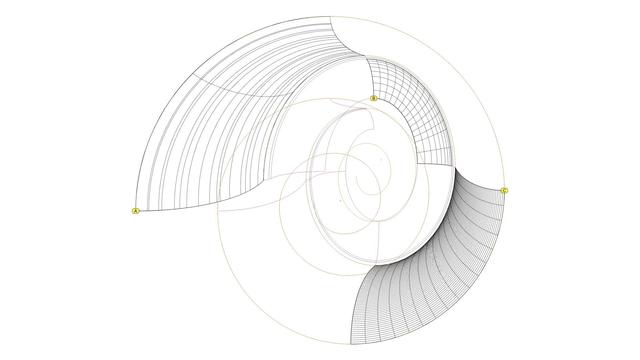
As mentioned in https://pixelfed.social/p/Splines/807933255910367093, we mentally rotate the floor plan of the modern #IonicCapital 45° so that the volute #spiral curves lie flat on the XZ plane.
The top-left diagram shows the original volute spirals from https://pixelfed.social/p/Splines/800383518517869430. If you haven't already rebuilt them from disjointed arcs to seamless #NURBS curves as described in https://pixelfed.social/p/Splines/794199123072358090, do so now. Explode the whole spiral into constituent arcs, select all arcs for the outer spiral and join them separately, and repeat this step for the inner spiral. Then, rebuild both spirals with 256 segments each.
Volute spirals for the classic and modern variants are the exact same size, but the ones in the modern version appear smaller. That's an optical illusion because the spirals are rotated 90° in the modern version as shown in the bottom left diagram.
The bottom right diagram shows the placement of the volute spirals relative to the #profileCurves of the lower portion of the modern capital. The #voluteEye is slightly above and far to the right of the #astragal profile in the modern version compared to the classic version.
At this point, we make two copies of the volute spirals and trim them to the top of the #ovolo. In one copy we only trim away the outermost arms of the spirals while maintaining the inner spirals, as shown in the bottom right figure. In the other copy, we trim away the inner spirals as shown in the top right image.
The bottom right figure in https://babel.hathitrust.org/cgi/pt?id=mdp.39015031201190&view=1up&seq=142 shows the eye 6.5 parts (52 units) from column shaft. That's not an error, but poor documentation. See floor plan in https://pixelfed.social/p/Splines/807782440025967685 where x = 198 on the square is homologous to x = 250 on the circle. To reconcile, scale 52 by 250/198 = 65.656, or 66, and offset by 120 to get 186 units.
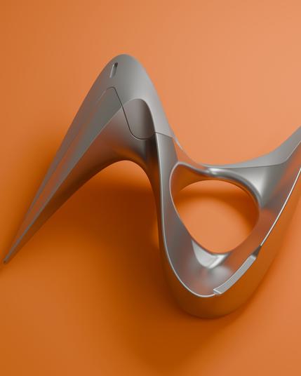
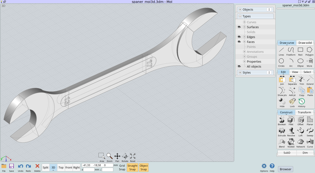
A #CAD model made with #Plasticity by Kuechmeister Swagger a German user with great skill in Plasticity and #Moi3D #nurbs #surfacing #xnurbs #car
https://youtu.be/P0l--9Oxokk?feature=shared
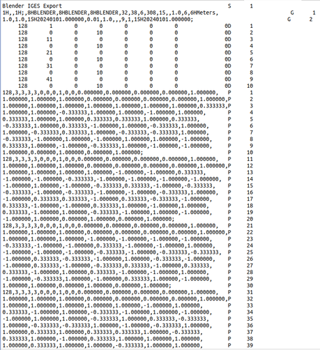
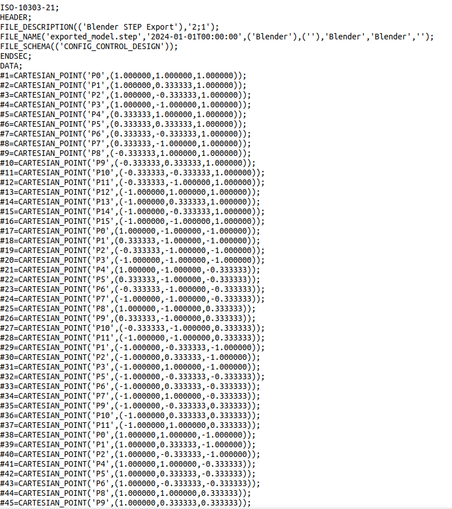
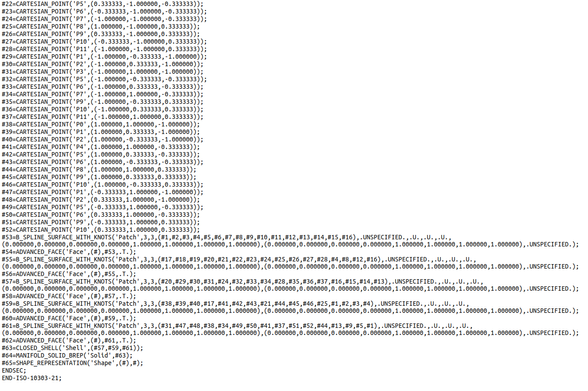
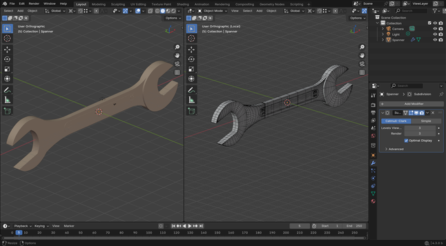
I've asked to #AI, an add-on to export #SubD to #NURBS from #b3d, the add-on managed to export something to both IGES and STEP, there are no errors, the exported files contain data structures but unfortunately any #CAD app managed to open those, although that seem like a failure, it's not, in fact it is the first time that I get an add-on that exports both in #IGES and in #STEP directly from #Blender without using external library, maybe next time I could be able to have a working add-on.
"Hilbert-Demons"
Some years ago, I experimented in "Moment of Inspiration" with different levels of Hilbert Curves.
This is a NURBS-loft between those levels, going from low to high to low with the same distance between each.
We are looking from the top on the resulting structure.
And I always see two super-heroes or demons facing each other... ;-)
The rendering and texturing was done in Thea Render.
#mastoart #hilbert #thea #loft #NURBS #3D #math #BeautyofMath
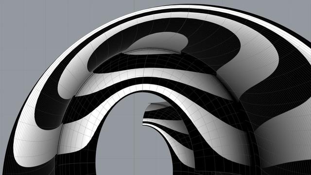
Look at the front view of three sections of the scroll surface labeled A, B, and C, and you will see a qualitative difference among them. Surface A appears crude and surface C appears refined, while surface B lies somewhere in between. While B and C are both acceptable, A is not.
The difference is due to two factors — the nature of the curves themselves and the degree of precision used.
Surface A is built using the circular arc sections for #volute #spiral (original and scaled) as #railCurves and the secondary curve sections as #sweepingCurves. The nature of the two sets of curves is different. Straight lines are 1st-degree curves, #circular or #conic sections (including ellipse) are 2nd-degree curves, but the projected sweeping curves (secondary curves) are 3rd-degree #NURBS curves.
Sweeping 3rd-degree NURBS curves along 2nd-degree arcs does not produce a salubrious effect. So we #rebuild the arcs into a 3rd-degree curve using the #CAD tool. When we do that, we are able to control how close the rebuilt curve should be to the original arcs in terms of precision.
I rebuilt each arc in the spirals using 16 subsections, and the effect is visible in surface C.
Look at surface A again. The cross-section arcs appear unevenly spaced compared to those of the other surface sections. To fix that, I also rebuilt the projected NURBS curves (secondary curves) to obtain what I call #tertiaryCurves.
For the frontmost sections, I rebuilt the sweeping curves using 64 subsections, and for the rear sections, I rebuilt them with 8 subsections.
Experiment with what produces pleasing results, but remember that higher precision curves require more processing time as well as more storage space.
I got this impression because I spent years searching for credible and actionable documentation on how to recreate this beautiful design in a #CAD tool. In the Age of Internet and Social Media, my web searches always disappointed me because the results lacked something vital in one respect or another. Over the years, I created hundreds of versions of the scroll that looked so perfect and pleasing that I thought I had cracked it, only to find some flaw or another in my work.
So, it is with caution that I present my work on the scroll in the hopes that someone will build upon this knowledge and either validate the design, or correct it and share it with me and the rest of the world.
Looking back at my progress, I'm now surprised at how remarkably simple and elegant the design is that defied familiar geometrical construction techniques I had been using until now.
As I mentioned in my introductory post, this design can be recreated by drawing simple 2-dimensional lines and circular arcs, but instead of just #primaryProfileCurves, we will use up to three additional sets of curves — #secondaryCurves, #tertiaryCurves, and #quaternaryCurves — each derived from the previous set.
I extracted the #primaryCurves after a lengthy trial-and-error process that involved #curveFitting image scans from #Vignola’s book, #RegolaArchitettura. I had to #reverseEngineer the details because the measurements have either been lost, or are locked away in some library.
Even though we start with lines and arcs, the end results are always #NURBS curves and surfaces, but everything is done by the CAD tool, and no additional math is needed.
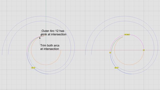
Create a 270° circular arc of radius 1 part (24 units at 3x scale), spanning quadrants 2, 3, and 4 as shown in orange for the #eye of the volute. The arc for the eye intersects arc 12 of both inner spiral (shown in green) and outer spiral (shown in magenta).
Outer arc 12 makes a kink where it meets the orange arc as seen in the left diagram. Discard the magenta arc 12. We can do better.
Trim both the inner arc 12 (green) and the orange arc for the eye where they meet and discard the right portions of both.
Finally, perform an #arcBlend between points A and B as shown in the right diagram. Arc blend is a new operation we are seeing for the first time. Previously we used #tangencyBlend to blend various sections of the #primaryProfileCurves for the #shaft of an #IonicColumn [https://pixelfed.social/p/Splines/791723063470910081]. Arc blend also maintains tangency, but instead of generating freeform #NURBS curves for blending, it exclusively uses one or more sections of circular arcs to blend the ends.
Join all segments of the inner spiral, outer spiral, eye, blended arcs, and straight lines near the top-left of the volute to create a single #closedCurve.
Mark the center of the eye as the origin or base point for #moving, #scaling, and other #transformations, and don't forget to scale the entire design to 1/3 using a scaling factor that has a high degree of precision, e.g., 0.33333333.
I mentioned that Dürer's approximation of a #logarithmicSpiral is close, but doesn't fit perfectly. So far there's nothing that doesn't fit. The fit issue only comes up during #scroll construction.
This concludes the task of volute construction. Next, we will look at creating the 3-dimensional volute slab using this closed volute curve and adapt it for the recessed #channelGroove in the slab.
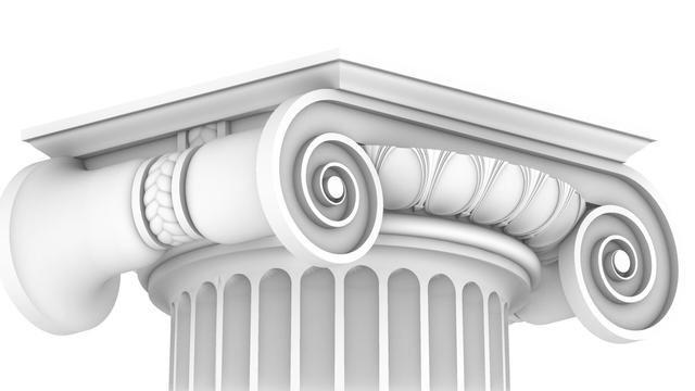
The Ionic capital is complex, but not unapproachable. We will systematically construct everything in this draft rendering using just straight lines and arcs as promised in https://pixelfed.social/p/Splines/789956327130679640, with the exception of the #cymaReversa near the top and the 3-strand braid on the ribbon.
In this rendering, the cyma reversa near the top is made using a flattened half-turn of a #helix, but it can also be constructed using elliptical arcs as I described in earlier posts.
The braid is a #periodic shape with infinite variety and is also based on a helix. You can vary the number of strands, their thickness, pitch, and so on, none of which are essential to the Ionic Order itself. They're only a jumping point for further exploration.
The eggs in the 'eggs and darts' motif can have different shapes. They can be convex like real eggs or concave as shown here, but the top is almost always sliced off. The total depth of the convex or concave shapes can vary, but only within a range of 1 part, or 8 units.
The #volutes in the front and back of the capital are based on #spiral shapes, of which there are many different kinds. Some have #continuous curvature changes, while some do it in #discrete steps, like #fibonacci spirals that can approximate #logarithmic spirals seen in nature, e.g., nautilus. When curvature changes are discrete, the spiral arms can diverge in #arithmetic, #geometric, or some other sequence.
We will construct all of these, and most notably the smooth, sweeping surface of the scrolls using just straight lines and arcs, and let the #CAD software deal with delicate #NURBS curves and surfaces.
In https://pixelfed.social/p/Splines/791723063470910081, we blended the bottom end of the 60° arc and the top end of the long interpolated curve between points J and K. Now blend the bottom end of the interpolated curve and the top end of the straight line between points B and C to obtain the 3rd and final #NURBS segment for the #primaryProfileCurve of the shaft.
Just like there's a #cavetto and #fillet near the #neck of the shaft, there is a fillet and cavetto near the foot of the shaft. However, there is a subtle difference between the two. The cavetto near the neck is tangential to the blended #NURBS curve that is not a straight line. The profile curve for the cavetto near the foot is tangential to a straight line.
There is a special name for a cavetto that is tangential to a straight line or flat surface, like the two cavetto moldings in the #dado of the #pedestal. It's called a #conge. Another alternate name for the cavetto molding is #cove, which is evocative of "cave" because of its concave profile curve.
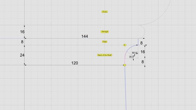
Above the neck is a fillet 8 units tall and an #astragal 16 units tall that #Scarlata puts in braces in the column shaft section within his tables of #VignolaProportions, with a note saying they are not counted as part of the shaft but are accounted for as part of the #capital.
I decided to include the top fillet as part of the shaft and keep the astragal with the capital. It does not change the design or alter the proportions in any way, but the inclusion of the fillet makes it more practical for #3DPrinting and #CNCMilling of the neck. This concludes the profile curve for the shaft with a height of 291 parts or 2328 units + 8 for fillet.
The column shaft is tapered in the upper 2/3 due to #entasis whose purpose is to make optical corrections to the shape of the column which, without correction, appeared concave near the top.
The neck is conceptually divided into three bands, each 1 part (8 units) tall. In the top 2/3, we draw a circular 90° arc with radius of 16 units, divide it into thirds, and discard the lower 30° portion.
Then, blend the lower end of the arc and upper end of the interpolated NURBS curve to create a new NURBS curve shown here in magenta. Zoom in, and you will see that it deviates slightly from the original 90° arc. This is because the blended curve is tangential to the 60° arc and the longer NURBS curve. When joined, the three sections form a smooth #continuouslyDifferentiable NURBS curve.
This level of precision is only needed for engineering work. If you just want a #charcoal #sketch, #draw in #ink, #paint in #watercolor, or even make #clay or #ceramic #basrelief, then you don't even need a #CAD program. A compass and protractor are sufficient. Just blend the shapes by hand as closely as you can. The imperfections, if any will be imperceptible.
This brings us back to the previous post. If you're not using CAD, how do you obtain the 8 points C through J using manual tools?
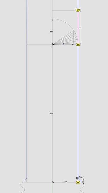
Look closely at the radiating lines, first of which passes through point B and the last one reaches point 8. An easy way to find the angle between these two lines is to use basic trigonometry.
Focus on the center of the arc, follow up to point 8, and then drop down vertically where the horizontal line is split at 120 units, and close back to the origin. This is a right triangle whose hypotenuse is the radius of the arc. The cosine of the angle between the base and the hypotenuse is 120/144 = 0.83333333. So the angle itself is arc cosine of 0.83333333, or 33.55730976°. For hand drawing, round it off to 33.6°. Then divide that into 8 parts of 4.2° each to plot points 1 through 8.
The #shaft of an #Ionic column is not perfectly cylindrical but gradually tapers off in the top 2/3 of the shaft. As such, the #primaryProfileCurve is not a straight line, nor is it composed of regular arcs. Instead, it is a complex amalgam of straight lines, circular arcs, and #NURBS curves, where the fancy acronym stands for an even fancier name — "Non-Uniform Rational B-Splines."
So, the promise [https://pixelfed.social/p/Splines/789956327130679640] was that we were going to get through this by drawing just straight lines and arcs. How are we going to draw NURBS? The answer is that we won't. The #CAD program will, as long as we give it sufficient information to carry out the task.
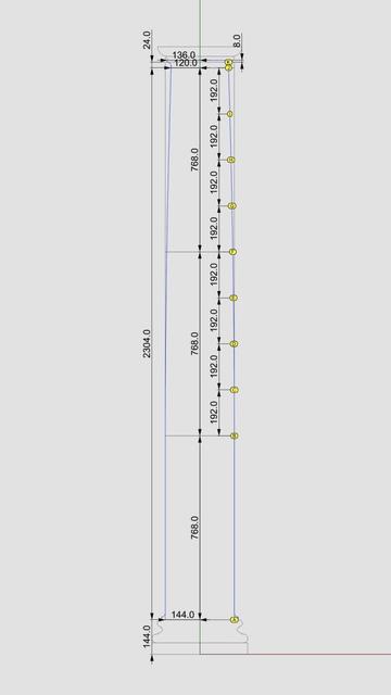
There are three NURBS curves in the profile shown in the plan. The longest and the most important one is between the points marked C through J. There is a smaller one between B and C, and an even smaller one between J and K.
While all three NURBS curves are mathematically similar, the information we must provide to the CAD program for the longest one is different from the other two short ones, and the operations the CAD program carries out to construct the longest one and the other two curves is also different.
This brings us to two new operations — #interpolate or "fit through points," and #blend shapes (existing curves or surfaces). When you choose a CAD program, make sure it supports NURBS, #interpolation, and #blending.
Starting at the bottom of the shaft, point A is 144 units from the #columnAxis, and so is point B, which is also 768 units higher than A. Starting with C through J, the points gradually move closer to the axis until J is exactly µ * 5/6, or 120 units from the axis. These points are equidistant vertically — all 192 units apart. However the horizontal distance is non-uniform.
In the next post we will mark the 8 points C through J using using one arc and 8 straight lines — I will keep my promise.
#genuary2 Layers upon layers upon layers. #genuary #nurbs #grasshopper
Here a little guide on how import a #IGES #Nurbs surfaces ready for Subdivision Modifiers, isn't always a suitable workflow, but can help maybe in some cases. #blender #b3d #Blender3D
https://blenderartists.org/t/how-import-iges-surface-topology-into-blender-ready-for-subd/1556580
#Nurbs #Surface topology imported into #Blender without using add-ons to do the #retopology. It was a long job, also because I had to understand some things well, but with this method it is possible to import #CAD objects, and apply subdivision surfaces, in many cases the surfaces need to be reconstructed, but with #Moi3D it is quite simple. #b3d #blender3d
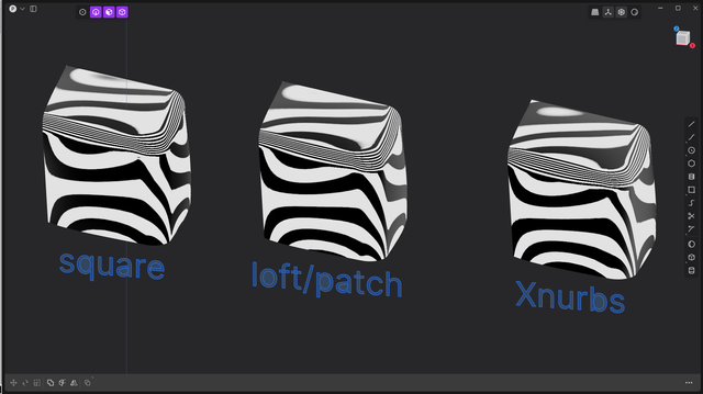
Many went crazy for #Xnurbs/square command, but with #Plasticity3D sometimes using the standard commands results in better surfaces, however, XNurbs creates simpler surfaces, but sometimes the CVs are a bit messy. #Nurbs #CAD
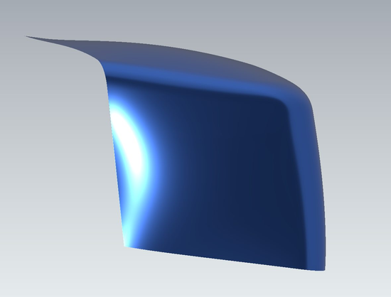
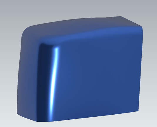
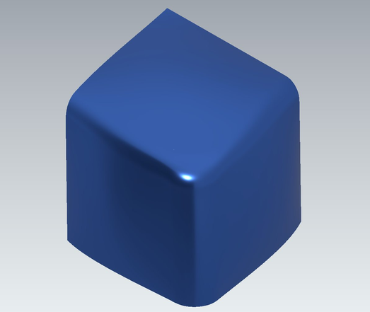
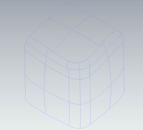
A corner ball patch, with two radius fillet and surfaces continuity G2. #NURBS #surfaces #CAD #Plasticity3D
