
555-Based Square-Wave and Triangle-Wave Function Generator Build for Beginners https://hackaday.com/2026/02/07/555-based-square-wave-and-triangle-wave-function-generator-build-for-beginners/
#Hardware #Howto #555timer #Functiongenerator #Squarewave #TL082opamp #Trianglewave
#555timer
555-Based Square-Wave and Triangle-Wave Function Generator Build for Beginners
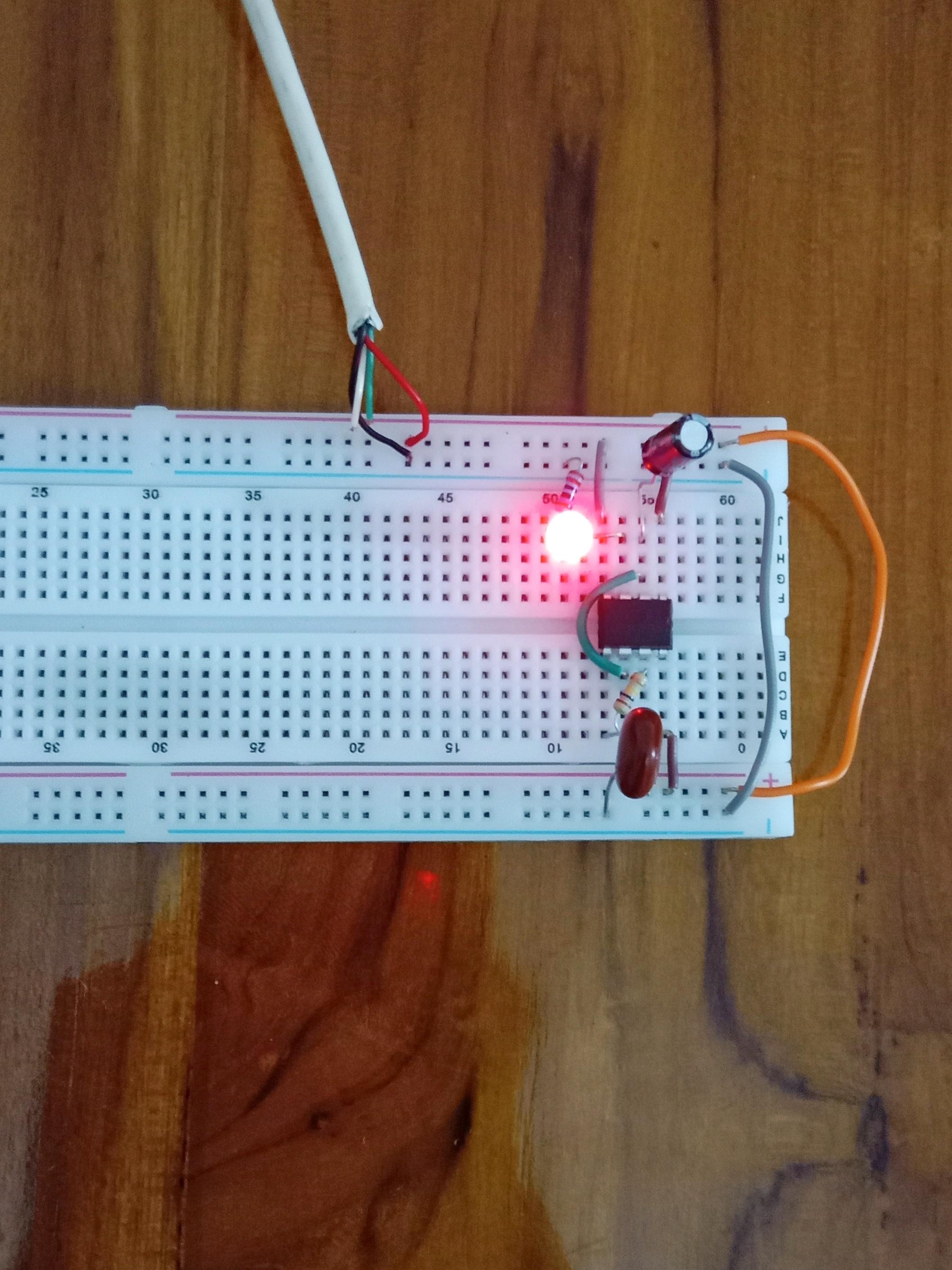
![<div><img alt="The function generator circuit on a breadboard" class="attachment-large size-large wp-post-image" height="450" src="https://hackaday.com/wp-content/uploads/2026/01/Function-Generator-Build-for-Beginners-banner.jpg?w=800" style="margin: 0 auto; margin-bottom: 15px;" width="800" /></div><p>Over on YouTube [Andrew Neal] has a <a href="https://www.youtube.com/watch?v=KfFmZIZ67MM" target="_blank">Function Generator Build for Beginners</a>.</p>
<p><a href="https://hackaday.com/wp-content/uploads/2026/01/555-square-wave.png" target="_blank"><img alt="This is the 555 circuit we are building taken from the datasheet" class="alignright size-full" src="https://hackaday.com/wp-content/uploads/2026/01/555-square-wave.png" width="300" /></a>As beginner videos go this one is fairly comprehensive. [Andrew] shows us how to build a square-wave generator on a breadboard using a <a href="https://www.ti.com/product/LM555" target="_blank">555 timer</a>, explaining how its internal flip-flop is controlled by added resistance and capacitance to become a relaxation oscillator. He shows how to couple a potentiometer to vary the frequency.</p>
<p>He then adds an integrator built from a <a href="https://www.ti.com/product/TL082" target="_blank">TL082 dual op amp</a> to convert the circuit to a triangle-wave generator, using its second op amp to build a binary inverter. He notes that a binary inverter is usually implemented with a comparator, but he uses the op amp because it was spare and](https://files.mastodon.social/cache/media_attachments/files/116/033/787/537/829/184/original/f3b24557bb8bc036.jpg)


@labria Interesting. I am preparing an order at Digikey to replenish my parts stock and had a look on my 555. Only two left and I can't remember when I bought it. Could be 20 years ago, maybe longer. I can't remember when I used one last time in a project...
It's somehow sad because it is such a monument of IC history and it's great to hear it's not obsolete.
People, use more 555!
#electronics #555timer #555

Me: Why the hell is this opamp drawing half an amp when I turn it on?
Also me, later: Oh. Because it's a 555 timer...

New video (also the final one for this year)! I found a strange Hi-Fi component on the side of the road and am taking a closer look at it.
YouTube: https://youtu.be/gq-dF1hvItI
PeerTube: https://makertube.net/w/gaDpLnnWF4ehMRq8zvH4X7
#Pioneer #DT555 #DigitalAudioTimer #Repair #Restoration #555Timer #Oddity #AudioGear #Hifi #VintageAudio #VintageHifi


A Navajo weaving of an integrated circuit: the 555 timer
https://www.righto.com/2025/09/marilou-schultz-navajo-555-weaving.html
#HackerNews #NavajoWeaving #IntegratedCircuit #555Timer #TechArt #CulturalHeritage

@bengakai Congrats! Well done! 👍 #electronics #555Timer

Built my first little 555 astable timer today ⏱️⚡
Just a humble LED blinker, but it feels like magic when the circuit comes alive.
Maybe this is the start of my journey into electronics and 8-bit retro computing.
#Electronics #555Timer #RetroComputing #Maker

Jan Beta Makes A Simple 555 Based Logic Probe
#C64 #Commodore64 #555Timer #LogicProbe #ElectronicsDIY #CircuitBuilding #Instructables #ElectronicsTutorial #ILC555 #NE555 #DIYProjects #TestEquipment
https://theoasisbbs.com/jan-beta-makes-a-simple-555-based-logic-probe/?feed_id=1024&_unique_id=677bea5ce5c1e

Making a Simple 555 Based Logic Probe
New video! I'm building a simple 555 timer based logic probe from spare parts I had laying around.
YouTube: https://youtu.be/NhgjBUmnA7k
PeerTube: https://makertube.net/w/cuUPCfYmzMeL8DkFuXgW2a
#LogicProbe #DIYLabEquipment #LogicTester #NE555 #555Timer #Circuit #Schematics #DIY #Homemade #Electronics #Tinkering


The book shop has a magazine on sale from 2022. Not sure whether it's a reprint but I'm awfully tempted to buy it because of an article about the NE555. #555timer
Bringing the 555 Mini-Notebook to Video https://hackaday.com/2024/07/10/bringing-the-555-mini-notebook-to-video/ #engineer'smini-notebook #electronicstutorials #engineer'snotebook #tutorialvideo #classichacks #forrestmims #PCBHacks #555timer

Check out my latest article for @hackaday ...
https://hackaday.com/2024/07/10/bringing-the-555-mini-notebook-to-video/
#ForrestMims #MiniNotebook #555timer

The Eurorack ADSR PCBs are now available, more details and schematics on my website https://polykit.rocks/adsr
#eurorack #adsr #envelope #synthdiy #555timer

See Them Knocking with a Doorbell Alert https://hackaday.com/2024/06/21/see-them-knocking-with-a-doorbell-alert/ #homehacks #555timer #556timer #doorbell #led #9v

Blitz Badge City, Part 1
https://makertube.net/videos/watch/fd5f0b5c-8f58-45c3-b08f-1c35a04b6adc
Blitz Badge City, Part 2 [Finale]
https://makertube.net/videos/watch/faf37be7-484e-444a-8dcf-4e87e1285a59


Client Info
Server: https://mastodon.social
Version: 2025.07
Repository: https://github.com/cyevgeniy/lmst